Multiple Bearings in Spindle

Advert

Multiple Bearings in Spindle

Home Forums General Questions Multiple Bearings in Spindle

Viewing 25 posts - 26 through 50 (of 76 total)
  • Author
    Posts
  • #653508
    Steve Crow
    Participant
      @stevecrow46066

      Thank you for all the input.

      I will do some revised drawings with a simpler spacer. When it comes to abutment sizes etc. I've found this information for the bearings i intend to use so I can incorporate it into my drawings (which are to scale, by the way)

      I know what you mean about the stiffness. I had a look at the SKF link. This spindle has bearing spacing of 6x diameter which is nearly twice recommended.

      I need the length as this particular one will need to be able to slide at least 20mm in a 50mm long bush/sleeve. It will only be used in the vertical position for light drilling so I think I'll get away with it.

      I intend to make a shorter one as well for my lathe cross slide. That one will have to do some light milling so will be stiffer. I will watch your linked video later.

      Steve

      Advert
      #653531
      Steve Crow
      Participant
        @stevecrow46066

        This time I've drawn the shorter version, it's easier to see the whole thing. Bearings are 3.23 x diameter apart.

        20mm spindle 05s.jpg

        I've taken on board suggestions for simplifying the spacer tube and the dimensions have been adjusted so all abutments are to the SKF spec. for those particular bearings.

        There were also dimensions (0.2mm) for the fillet radius for abutments. I have inserts with that tip radius so that should work.

        Not sure how to lock the adustment nut. I can't find any wavy washers that fit such narrow confines. Suggestions welcome.

        Steve

        Edited By Steve Crow on 24/07/2023 15:09:38

        #653584
        Kiwi Bloke
        Participant
          @kiwibloke62605

          OK, more simplification. Probably.

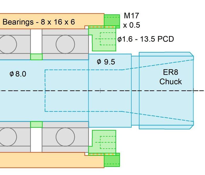
          Make the 'nose nut' without the flange you've drawn, so that, when tightened, it sticks out say 3mm beyond the end of the housing. The nut's OD is threaded along its entire length (easier to machine), and it has a couple of axial holes on its exposed face, for a pin spanner. When boring and screw-cutting the housing, make the threaded section longer, then part off say 3 mm. This parted-off section then screws onto the exposed threads of the 'nose nut' (taking the place of your flange), locking it. You'll need to make a couple of pin spanners (or a C spanner for the locking nut, if its face is too skinny for spanner holes) to tighten the nuts. (Sorry for that complication). I can think of other locking strategies, but this one seems the most elegant – so far…

          #653599
          Nick Wheeler
          Participant
            @nickwheeler

            I'd be more concerned about the M7 nut on the other end. Although both look like candidates for loctite.

            #653601
            Kiwi Bloke
            Participant
              @kiwibloke62605

              M7 Nyloc?

              #653608
              Andy_G
              Participant
                @andy_g
                Posted by Nick Wheeler on 25/07/2023 09:45:12:

                I'd be more concerned about the M7 nut on the other end.

                That nut can be done up tight, but it should be left hand thread for a clockwise spindle by rights (or backed up by a locknut).

                I think that the concern for the front clamp ring is because it will be used to set the bearing preload, so will need to be locked at the chosen position, rather than being done up tight.

                Edited By Andy_G on 25/07/2023 10:01:17

                #653609
                Clive Steer
                Participant
                  @clivesteer55943

                  I recently have replaced the spindle bearings in the head of a 8mm Leinen lathe. The arrangement of the bearings and spindle were as a cartridge using simple tubular spacers of slightly different lengths to provide bearing pre-load. Although the spindle was supported by only 2 bearing the same arrangement can work for 3 but, for the simplest arrangement, they would all need to be the same diameter or at least have the same OD.

                  The spindle would have a single diameter for its whole length the same as the bearing ID with an abutment at the front where the ER8 collet fits. There would be large tubular spacers matching the OD of the bearings and others with ID's matching the OD of the spindle. The two spacers between the front bearing have slightly different lengths that set the pre-load of the front bearings and the different lengths of the 2 longer one set the pre-load, if any, for the rear bearing. The outer tube would be be symmetrical with internaly threaded ends to retain the cartridge.

                  I think the attraction of this arrangement is that all the parts are very simple to make and alter if pre-loads need changing.

                  Some special bearings are paired with the width of the out race being different to the inner race so when assembled with equal length spacers the correct pre-load is provided. This was the case with the Leinen bearings which were £250 a pair and had to fitted the correct way around.

                  However it is relatively easy to shave a few thou/microns off the sleeves by lathe or stoning the inner or outer until you get it right.

                  CS

                  #653611
                  Steve Crow
                  Participant
                    @stevecrow46066

                    I may well be incorporating the rear nut into the pulley yet. That way won't the torque keep the nut locked?

                    Once I'm happy with the rest of the spindle design, I'm going to look at the drive etc.

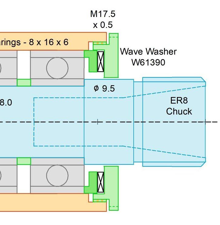
                    I like the nose nut lock suggestion and will do a drawing but I've also found a wave washer that fits so will draw one for that as well.

                    I would rather not use loctite on this. No objection to it, I use it all the time, bu I'd rather not on this spindle.

                    Steve

                    #653614
                    Clive Steer
                    Participant
                      @clivesteer55943

                      Steve

                      It is common for ultra accurate spindles to have a separate bearing(s) for the drive pulley to take belt side loads and an axial spline or pin coupling to the spindle. This is the arrangement of the Hardinge lathe and my Bridgeport M milling head. On the Hardinge this done so that no belt/pulley rumble gets transmitted to the spindle allowing super surface finishes to be obtained.

                      Given the size of the cutters you are likely to be using most of the power will be needed to drive viscous friction loads of the bearing lubrication. The are some excellent brushless DC motors cheaply available that could be mounted axially provided you have the space.

                      CS

                      #653620
                      Steve Crow
                      Participant
                        @stevecrow46066

                        Two more drawings. The first is the nose lock nut suggested by Kiwi Bloke.20mm spindle 06 nose.jpg

                        The second one has a wave washer in the nose. It's shown loaded on the drawing dimension wise.20mm spindle 07 nose.jpg

                        This one looks kind of complicated. I'm sure it can be simplified.

                        Steve

                        #653621
                        Steve Crow
                        Participant
                          @stevecrow46066

                          Hi Clive, that Leinen system sounds simple and elegant but I should imagine it's fiendishly difficult to match the lenghts of the tube for an optimal result.

                          I have seen that "remote pulley" system on a few machines. I was thinking of useing something similar for my longer spindle.

                          Steve

                          #653622
                          Dave S
                          Participant
                            @daves59043

                            I would consider a spacer for the outer races, then the nose nut can be locked up tight.

                            To create the right preload is a case of making the inner race and outer race spacers different lengths.

                            if you have access to a surface grinder then you can make them initially at the same time – this creating a

                            paired length, and then selectively lap the inner one shorter.

                            On the back nut a pair of lock nuts should do.

                            Dave

                            #653630
                            Kiwi Bloke
                            Participant
                              @kiwibloke62605

                              Nah, don't like the wave washer. You'd still need to lock the nut. The wave washer does provide spring pre-load to the bearing pair, but it also destroys axial stiffness.

                              I'd rather forgotten about the other end… If you're driving this with a pulley, it can be screwed on (I'd assumed that, much earlier), and a plain locknut added. Don't rely on just a thread for accurate location of the pulley, though; it should be a snug fit on the plain section of the shaft, to ensure it runs true, and have a boss, outboard, which is threaded. This has the added advantage of getting the pulley as close to the tail bearing as possible.

                              Clive's comments above, about (partially) isolating the pulley from the shaft, is good stuff, and also applies to drilling machine quills, of course. But we're chasing simplicity, aren't we?

                              Edited By Kiwi Bloke on 25/07/2023 12:23:31

                              #653640
                              derek hall 1
                              Participant
                                @derekhall1

                                Further to my post, I found the article I was looking for !….

                                There was a construction article in the Model Engineer three parts to it dated 19th June, 17th July and 21st August 1992 by a Mr. D. Broadley called "A Grinding Spindle".

                                He described a heavier duty version of it in the last part, for those who have access to older copies of the ME it is worth a look.

                                #653642
                                Clive Steer
                                Participant
                                  @clivesteer55943

                                  Steve

                                  The elegance of the tube system is you make the tubes and spacers all the same length at first and then shave a thou or two off one to get the correct pre-load. The thin spacers between the front two bearings are a bit more tricky to do but you can super glue them to a face plate and skim. Final gapping can be done by "stoning" on say a diamond lap. The pre-load is determined by the difference in length rather than the absolute length so much easier to measure accurately with feeler gauges. The tubes can have fairly thick walls which improves the cartridge and spindle rigidity. Also their inner and outer diameters don't have to be that accurate. You can make one long tube and then part off the thinner spacers and only the face that the parting tool created needs to be trued up.

                                  I'm not sure that given the ER 8 collets and the small cutter/drill you are expecting to use whether you need two bearings at the front.

                                  I've just upgrade a sensitive vertical drill by using a bought spindle with ER11 collets. The spindle is a straight 12mm diameter X 150 mm long and in my case runs in oilite bushes. I don't know if similar spindle are available for ER8 but it would save a lot of work.

                                  The Leinen system used special bearings which had to be assembled in the correct orientation so on reflection the spacing tubes were probably equal length.

                                  CS

                                  #653643
                                  Steve Crow
                                  Participant
                                    @stevecrow46066

                                    Here is the complete shorter spindle for my lathe cross slide.-

                                    20mm spindle 06s.jpg

                                    The pulley is an arbitrary diameter for now but will use a 3mm drive belt. I forgot to dimension it but the pulley inner/boss outer diameter is 8mm.

                                    The longer spindle will be acting as a quill in a sensitive drill so I'm going to devise an isolated pulley system. I've not even started on the design of all that, I wanted to make sure I could make an effective spindle first.

                                    Steve

                                    #653645
                                    Andy_G
                                    Participant
                                      @andy_g
                                      Posted by Steve Crow on 25/07/2023 10:03:00:

                                      I may well be incorporating the rear nut into the pulley yet. That way won't the torque keep the nut locked?

                                      Yes – my comments would only apply to the case where you have a nut retaining the bearing only (the design in the post on 24/7 15:02).

                                      For the latest iteration, I don't see much point in threading the pulley *and* fitting locknut. As you say, the drive torque will keep things done up.

                                      #653662
                                      bernard towers
                                      Participant
                                        @bernardtowers37738

                                        the rear nut could be a GHT type with slit and clamp screw.

                                        #653674
                                        Steve Crow
                                        Participant
                                          @stevecrow46066

                                          For the latest iteration, I don't see much point in threading the pulley *and* fitting locknut. As you say, the drive torque will keep things done up.

                                          My reasoning behind the locking arrangment is twofold.

                                          Firstly, ease of assembly. The spindle and bearings can all be assembled and locked up then loaded into the housing from the front. Then the pulley and locknut can be nipped up.

                                          Secondly, the pulley can be changed for other sizes without disturbing the spindle.

                                          I need to make the rear inner nut a bit thicker so I can access the flats with a spanner. This will push back the pulley by a couple of mil.

                                          Steve

                                          #653728
                                          Kiwi Bloke
                                          Participant
                                            @kiwibloke62605

                                            I think you may be over-emphasising the ease of assembly. The tail bearing will look after itself as the assembly is pushed together. You're right, and others have pointed out, that a threaded-on pulley will self-tighten, and so doesn't really need a locknut. It's analagous to a screwed-on lathe chuck. But, should you wish to run the spindle in reverse, a locknut becomes necessary.

                                            So, to simplify further, delete the green pulley hub, and thread the pulley directly onto the shaft. As I suggested before (or meant to, it was getting late), the pulley should, in addition to a threaded bore section, also have a plain bore, for best location, and I think this should be adjacent to the bearing. Thus, on your latest drawing, the 7 mm dia becomes plain, and the 6 mm diameter is threaded. The pulley itself is positioned as far to the right as possible, (over the plain bore section) to reduce the effects of belt tension. It will be easy enough to swap pulleys, and it won't disturb the shaft.

                                            I think the spacer tube could be simplified, with plain, not stepped ends. Its right hand end can remain 7.1 mm ID, if the spindle's 7.1 mm OD extends just a tad under the inner bearing's inner track. I'd think that its left end could also remain 9.5 mm OD. It doesn't matter if it's a larger diameter than the bearing's inner track's OD.

                                            One complication you might consider is a lightly pressed-on flange, on the 9.5 mm Diameter of the shaft, acting as a flinger or muck shield.

                                            It's looking pretty well done – time to cut metal soon!

                                            #653754
                                            Steve Crow
                                            Participant
                                              @stevecrow46066

                                              Forgot to mention a third reason for the lock nut arrangment.

                                              I can use a spanner on the rear inner lock nut to hold the spindle for undoing the collet nut. And the outer one for tightening of course.

                                              Steve

                                              #653769
                                              Kiwi Bloke
                                              Participant
                                                @kiwibloke62605

                                                Hmmm. I think that the two spanners should be as close together as possible, so that you can squeeze them together, like pliers handles, and also to avoid inadvertently applying a couple to the spindle's mounting, and possibly shifting it. By squeezing the spanners together, you can more-or-less avoid applying any force to the spindle assembly, other than the required torque. An open-ended spanner, made from say 3mm sheet, could bear on a couple of flats on the 9.5 mm Dia section, just behind the nut. Make the slots a clearance fit on the thickness of the spanner, and it'll behave itself better. Or a hook spanner, locating into radial holes. Might have to fiddle with dimensions to make sure there's room.

                                                Just another suggestion…

                                                (Should I just shut up now, and let you make the thing?)

                                                #653775
                                                Steve Crow
                                                Participant
                                                  @stevecrow46066

                                                  Just another suggestion…

                                                  (Should I just shut up now, and let you make the thing?)

                                                  No please, all suggestions are welcome. I couldn't have got this far without the help from various posters and I'm very grateful.

                                                  Before I even start getting in materials, I want to make sure I've got a good, sound design that can be replicated and scaled.

                                                  I'm going to have a few days now away from the "drawing board" as I've got other workshop projects I've been neglecting!

                                                  Cheers

                                                  Steve

                                                  #653811
                                                  Iain Downs
                                                  Participant
                                                    @iaindowns78295

                                                    I'm particularly interested in how you plan to machine the spindle, Steve. It looks to me like a challenging level of precision for a mini-lathe. Certainly beyond what I think I could achieve.

                                                    When you get back to your drawing board, perhaps you could sketch out your approach!

                                                    Iain

                                                    #653837
                                                    Steve Crow
                                                    Participant
                                                      @stevecrow46066
                                                      Posted by Iain Downs on 26/07/2023 16:53:13:

                                                      I'm particularly interested in how you plan to machine the spindle, Steve. It looks to me like a challenging level of precision for a mini-lathe. Certainly beyond what I think I could achieve.

                                                      When you get back to your drawing board, perhaps you could sketch out your approach!

                                                      Iain

                                                      Hi Iain, do you mean the actual spindle itself or the nuts,housing etc.?

                                                    Viewing 25 posts - 26 through 50 (of 76 total)
                                                    • Please log in to reply to this topic. Registering is free and easy using the links on the menu at the top of this page.

                                                    Advert

                                                    Latest Replies

                                                    Home Forums General Questions Topics

                                                    Viewing 25 topics - 1 through 25 (of 25 total)
                                                    Viewing 25 topics - 1 through 25 (of 25 total)

                                                    View full reply list.

                                                    Advert

                                                    Newsletter Sign-up