Moving first mandrel gear on an ML!0

Advert

Moving first mandrel gear on an ML!0

Home Forums Beginners questions Moving first mandrel gear on an ML!0

Viewing 25 posts - 1 through 25 (of 33 total)
  • Author
    Posts
  • #737542
    Andrew Tinsley
    Participant
      @andrewtinsley63637

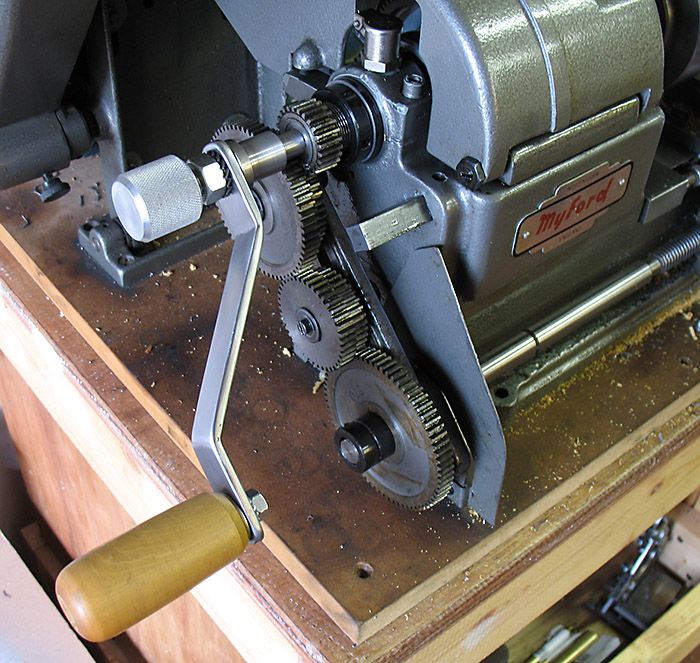
      I want to cut a 1.25 mm thread on my Imperial ML10. The gear train is simply The first gear on the mandrel (35) then50, 63, 40, 35and finally the leadscrew gear, 70.

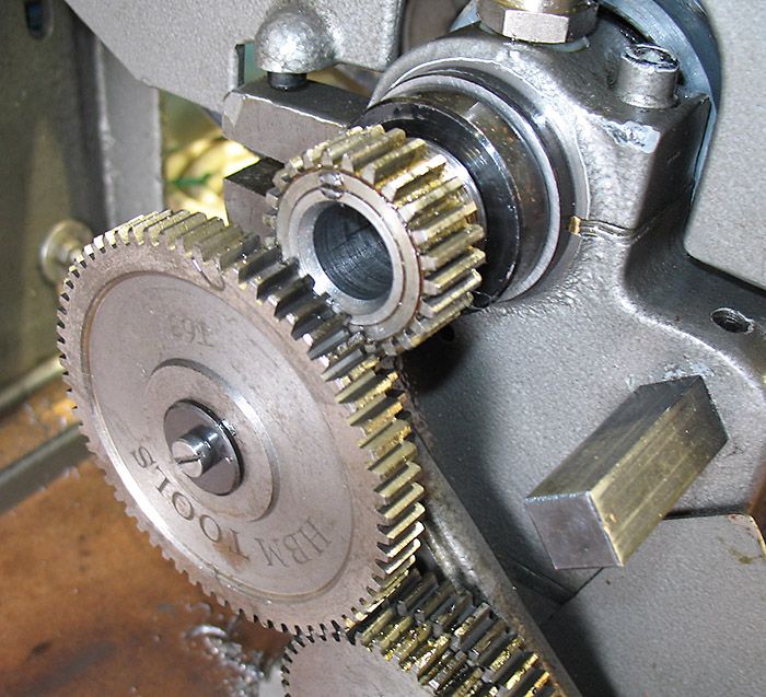
      The snag is that the 35 tooth mandrel wheel spans both of the first pair of gears, so it will only engage with the 63 gear and not the required 50.

      The 35 tooth mandrel gear appears to be screwed on to a threaded part of the mandrel. So I should be able to screw it to the correct position, but it appears to be solidly fixed to the threaded section.

      I gave up at this stage as the area was covered in black grease and I could not see the set up until I cleared off the black gunge. So I retired to a glaas of white wine and the ML10 handbook. The diagram sows the 35 tooth gear having a 2BA grub screw. Does this lock the gear on the threaded shaft. If so, presumably this needs slackening off and 35 gear can be screwed along to its correct position?

      Or have I completely lost the plot here and there is something I have completely missed?

      Andrew.

      Advert
      #737551
      jim1956
      Participant
        @jim1956

        I don’t have an ML10 but I downloaded a copy of the manual since it has some useful gear tables relevant to my Randa, plus I used an ML10 25T spindle cog to repair the backgear on my lathe.

        Your 35T gear seems odd, the ML10 has a fixed 25T boss gear.

        35  50 63 40 35 70 is way off, giving a 28% error on a 1.25mm pitch

        25 50 63 40 35 70 gives the usual 0.012% error (about the best you’ll get without a 127T gear)

        Formula is driven1/boss x driven2/ driver1 x leadscrew gear/ driver2 x leadscrew tpi = output tpi

        If you can change the spindle boss cog but can’t change the orientation relative to the first compound then a 27T spindle cog doesn’t need a double compound

        27 idler 40 35 60 also gives a 0.012% error

        Regards  Jim


        #737613
        bernard towers
        Participant
          @bernardtowers37738

          looking on lathes.co.uk site it looks like the gear is held on by a grub screw in line with the shaft.

          #737633
          JasonB
          Moderator
            @jasonb

            looking at the spares on the Myford site the spare 25T gear is not threaded and neither is the end of the spindle. Other images on the web show the gear frush to the end with a screw along the joint between gear and spindle.

            This one also shows the gear driving a 50T with a 63T next to it

            #737643
            Clock polisher
            Participant
              @clockpolisher

              Good morning,

              I’m currently in the process of rebuilding a Speed 10.

              The threaded portion of the mandrel is for the locking collar used to adjust bearing end-float.

              It does not extend under, or play any part, in the fixing of the 25 tooth standard gear.

              As has already being stated that is held in place with a grub screw.

              regards,

              David

              #737644
              Brian Wood
              Participant
                @brianwood45127

                Andrew,

                I have an article in with Neil covering the ML10 lathe and other non gearbox lathes with 8 tpi leadscrews. When it will appear in print I don’t know but from the tables I worked out (I do not have an ML10) you can cut a thread of 1.25 mm pitch without having to do anything to the 25T fixed spindle gear.

                Set up is:- Spindle 25 drives 50 coupled to 55 as the next driver to 70 on the leadscrew. You will need an idler to link the 55 to the 70T gears. Result is 1.247 mm

                Regards  Brian


                #737665
                Michael Gilligan
                Participant
                  @michaelgilligan61133
                  On JasonB Said:

                  […]

                  Borrowing the picture from Jason’s post for reference ^^^

                  and stating the obvious !

                  .

                  Using an axial grub-screw [or set-screw, depending on geographic preference] on the joint line is a very effective alternative to fitting a key, and is intended to be a semi-permanent arrangement.

                  MichaelG.

                  #737667
                  JasonB
                  Moderator
                    @jasonb

                    Brian, if the problem existed then your 50/55 pair would be more of a problem than the 50/63 as they are closer in diameter so would more likely clash with the 25T.

                    This is something that playing with online calculators does not tell you as they don’t always take into account what actually fits on a banjo.

                    I wonder if Andrew is simply putting the 63T of the pair against the banjo and that is why it is engaging rather than the 50T?

                    #737669
                    Andrew Tinsley
                    Participant
                      @andrewtinsley63637

                      Apologies for the brain fade I should have said 25 tooth mandrel gear Thanks Jason, for the image of the 25 t mandrel wheel. Mine is way to the left of the one in your image and straddles both the 50 t and 63 t gear.

                      As the 25t gear has a plain boss, then I will forget about screwing it further on the mandrel. I will locate the 2BA grub screw and see if slackening that off will allow the gear to go to the RHS and clear the 63 tooth wheel.

                      Thanks everyone,

                      Andrew.

                      P.S. Thanks Brian, if all else fails then your alternative change wheel selection will be used!

                      #737687
                      Brian Wood
                      Participant
                        @brianwood45127

                        As an old timer with a long memory, the photo of the fitting of the 25T gear to the spindle is identical to the arrangement Myford used on the ML4 lathe.

                        The difference between the fitting in 1945 and the ML10 is the absence of tumbler reversing on the more modern lathe.

                        Thank you Andrew, I hope it is helpful.

                        Jason. I was trying to use the regular set of Myford issue gears as much as possible in the tables that I hope will appear in the article.  Brian

                        #737697
                        Hopper
                        Participant
                          @hopper

                          Some pics of what you have would sure be helpful. Trying to imagine what is going on from your description is difficult.

                          It sounds like your  banjo, or something, is not quite in the right position.

                          But hard to tell in the dark.

                          #737705
                          JasonB
                          Moderator
                            @jasonb
                            On Andrew Tinsley Said:


                            P.S. Thanks Brian, if all else fails then your alternative change wheel selection will be used!

                            Brain Said

                            Jason. I was trying to use the regular set of Myford issue gears

                            The 50/55 on the same stud will suffer the same problem as the 50/63 on the same stud.

                            Something needs to move sideways or you need a single gear on the first stud so only that engages.


                            This is a 50/55 pair that don’t allow the 50T to mesh with the 25T which is the OPs problem not the actual gears used.

                            gear clash

                            This is something that affects many of the imported lathes where the fixed driver on the spindle is at least double the width of the banjo gears so whatever pair you put on the first stud MUST have the driven gear a larger size than the driver it is paired with

                            #737716
                            Andrew Tinsley
                            Participant
                              @andrewtinsley63637

                              Hello All,

                              I cleaned off the black grease and found the 2BA grub screw, Took this out and the 35 T gear slid off. The reason that the 35T gear  would not move further to the right was then clear. It was in fact hard against the shoulder of the raised thread on the mandrel (presumably this thread is used to tighten the mandrel bearings). Looks as if the mandrel has somehow been moved bodily  to the left!

                              So I would appear to have a limited range of options,

                              1/  Remove the mandrel and see if it can be moved to the right.

                              2/ machine the 35T bearing so that it can clear the threads on the mandrel. Would only need boring out by about 3mm.

                              3/ Reduce the entire width of the 35T wheel by the same 3mm. Interestingly enough the width of the 35 T gear is markedly greater than any of the change wheels,

                              4/  Make up some washers to fit the banjo studs and hence move all the banjo gears to the left.

                              Not keen on 1/ until I need to change the drive belts. 4/ could be a problem as I suspect the screw and retaining washers  would need shimming out to match.

                              I am tempted to go for 2/ as it is  the least intrusive.

                              Hopper, the set up should be clear from the photos that Jason posted. The Banjo is as per diagram in the handbook. The only thing I have not checked is if there should be a spacer washer between the Banjo and the lathe bed. This would move the banjo to the left and solve the problem. But not sure if the last gear on the banjo train would line up correctly with the leadscrew gear. I will check and get back to you.                             b

                              #737726
                              Brian Wood
                              Participant
                                @brianwood45127

                                Jason,

                                I see what you are getting at (at long last) and looking again at the pictures I get the impression that the spindle driver gear is wider that the other gears in the train downward.

                                Now we have the added complication mentioned by Andrew that the whole spindle appears to have been displaced to the left. That seems very odd to me.

                                A 5 tooth difference, 50 to 55, should be sufficient to allow the larger diameter gear to run clear of the teeth of the driver. Normally I would fit a shim between them to help with that and avoid rubbing but with a ‘fat’ gear at the start that doesn’t help things.

                                The calculation I worked out will be possible by swapping the driven gears, making a 50/70 pair on the stud at the 25T end and putting 55T on the leadscrew. Some shims may still be useful to get everything aligned happily.

                                Brian

                                #737737
                                Hopper
                                Participant
                                  @hopper
                                  On Andrew Tinsley Said:

                                  Hello All,

                                  I cleaned off the black grease and found the 2BA grub screw, Took this out and the 35 T gear slid off. The reason that the 35T gear  would not move further to the right was then clear. It was in fact hard against the shoulder of the raised thread on the mandrel (presumably this thread is used to tighten the mandrel bearings). Looks as if the mandrel has somehow been moved bodily  to the left!

                                  So I would appear to have a limited range of options,

                                  1/  Remove the mandrel and see if it can be moved to the right.

                                  2/ machine the 35T bearing so that it can clear the threads on the mandrel. Would only need boring out by about 3mm.

                                  3/ Reduce the entire width of the 35T wheel by the same 3mm. Interestingly enough the width of the 35 T gear is markedly greater than any of the change wheels,

                                  4/  Make up some washers to fit the banjo studs and hence move all the banjo gears to the left.

                                  Not keen on 1/ until I need to change the drive belts. 4/ could be a problem as I suspect the screw and retaining washers  would need shimming out to match.

                                  I am tempted to go for 2/ as it is  the least intrusive.

                                  Hopper, the set up should be clear from the photos that Jason posted. The Banjo is as per diagram in the handbook. The only thing I have not checked is if there should be a spacer washer between the Banjo and the lathe bed. This would move the banjo to the left and solve the problem. But not sure if the last gear on the banjo train would line up correctly with the leadscrew gear. I will check and get back to you.                             b

                                  The textbook picture posted seems to have a 25T gear, not your 35T gear, and seems to mesh perfectly with the one gear. It would seem yours has something different, somewhere.

                                  I would certainly be investigating banjo spacer before i started looking at moving your headstock spindle to the right to bring change gears into alignment. Sledgehammers and gnats come to mind.

                                  If you move the banjo outwards by the requisite amount, you should be able to move the leadscrew gear out by the same amount too. It is only held on the shaft by a key and those sliding collars with grub screws.

                                  Or it could be a matter of spacer washers on the studs behind the gears.

                                  Or it could be that your 35T gear is wider than the 25T gear in the posted picture above.

                                  Or it could be the 35T gear, which is threaded internally, has not been screwed far enough onto the headstock spindle before the locking grub screw was installed to lock it in position.

                                  Or it could be something else.

                                  Obviously, you are not seeing what the problem is. But someone else might if you could post some pics of what is actually going on on your lathe.

                                  #737746
                                  Andrew Tinsley
                                  Participant
                                    @andrewtinsley63637

                                    Sorry Hopper, I don’t have the ability to take digital photos. Jason’s last post clearly shows the problem I have. Before I start machining the 25T wheel. I will try to shim out the banjo as you suggest.

                                    Thanks,

                                    Andrew.

                                    #737748
                                    Martin of Wick
                                    Participant
                                      @martinofwick

                                      If you are having issues aligning the gears on the spindle with the banjo, check the location of the headstock on the lathe bed.

                                      The left side of the headstock casting should be flush with the left end of the lathe bed for the change gears to line up correctly with the the one on the spindle. When I say flush, this would be a good starting position, as some wiggle room left/right of 20 thou may be needed to optimise.

                                      I only mention this as the issue has come up before. It seems that ML10s may be prone to having their headstocks ‘interfered’ with and then not replaced in the correct location.

                                      Next to investigate is correct assembly and location of the banjo, although there is little to go amiss as it is so simple.


                                      #737767
                                      bernard towers
                                      Participant
                                        @bernardtowers37738

                                        Just one point I am alittle bit concerned about you keep mentioning grease there should be NO grease on the change wheels , use a LITTLE gear oil!!!

                                        #737779
                                        Michael Gilligan
                                        Participant
                                          @michaelgilligan61133

                                          In case anyone doesn’t have it for reference already … here is the ML10 [as opposed to the later Speed 10] manual:

                                          http://www.small-lathes.co.uk/Files/1.57452MyfordML10Manual.pdf

                                          Although the Parts-List is missing: It includes quite specific instructions about the the mandrel and the 25-tooth gear in the section about belt-changing … and Fig.8 nicely illustrates the standard location.

                                          MichaelG.

                                          #737783
                                          Michael Gilligan
                                          Participant
                                            @michaelgilligan61133

                                            EUREKA

                                            … I knew I had seen it somewhere !

                                            Speed 10

                                            https://www.instructables.com/Stripping-a-Myford-ML10-lathe-Speed-10-headstock/

                                            MichaelG.

                                            #737785
                                            Brian Wood
                                            Participant
                                              @brianwood45127

                                              Just to add a further thought to the mix, which may or may not have any relevance in this example, but could explain the apparent left shift of the spindle—is there a thrust bearing missing at the front end?

                                              Brian

                                              #737804
                                              Andrew Tinsley
                                              Participant
                                                @andrewtinsley63637

                                                I think Martin has put his finger on at least part of the problem. The headstock overlaps the bed by a goodly amount to the left. So it is worthwhile to move the headstock to the right.

                                                Now comes the red face, despite having the ML10 handbook, I have not got a clue as to what to slacken off in order to allow the headstock to move rightwards. I simply can’t understand how this works, despite having the diagram in front of me!

                                                Can anyone help?

                                                Andrew.

                                                #737810
                                                Andrew Tinsley
                                                Participant
                                                  @andrewtinsley63637

                                                  PROBLEM SOLVED!

                                                  The headstock is held on the bed with a couple of lugs at the rear. Just the same mounting style as the fixed steady and the Rodney mini mill.

                                                  Slacken off the two retaining bolts (1/4 BSF) and you can easily push the headstock to the right. Thanks to Martin of Wick for this information. I can consign to the bin, my adapter plate, which was intended to move the whole banjo to the left.

                                                  Thanks to everyone that have responded to my pleas for help! Would you just know that the remedy was so simple, I hang my head in shame.

                                                  Andrew.

                                                  #737816
                                                  Michael Gilligan
                                                  Participant
                                                    @michaelgilligan61133

                                                    Never mind the shame, Andrew … You have sussed it, and that’s what matters !

                                                    MichaelG.

                                                    #737858
                                                    Hopper
                                                    Participant
                                                      @hopper
                                                      On Andrew Tinsley Said:

                                                      Sorry Hopper, I don’t have the ability to take digital photos. Jason’s last post clearly shows the problem I have. Before I start machining the 25T wheel. I will try to shim out the banjo as you suggest.

                                                      Thanks,

                                                      Andrew.

                                                      My apologies for the unfounded assumption everyone has a smart phone with camera these days! I thought I was the last person in the world to get one, but obviously not! Well done.

                                                      And glad Martin of Wick has solved your problem for you. Moveable headstock? Who would think it? Very strange. Outside the box, that one.

                                                      Enjoy your metric screwcutting.

                                                    Viewing 25 posts - 1 through 25 (of 33 total)
                                                    • Please log in to reply to this topic. Registering is free and easy using the links on the menu at the top of this page.

                                                    Advert

                                                    Latest Replies

                                                    Home Forums Beginners questions Topics

                                                    Viewing 25 topics - 1 through 25 (of 25 total)
                                                    Viewing 25 topics - 1 through 25 (of 25 total)

                                                    View full reply list.

                                                    Advert