Mounting DRO scale on rough cast iron surface

Advert

Mounting DRO scale on rough cast iron surface

Home Forums Beginners questions Mounting DRO scale on rough cast iron surface

Viewing 12 posts - 1 through 12 (of 12 total)
  • Author
    Posts
  • #602069
    Y C Lui
    Participant
      @yclui16187

      Just wondering how to prevent the scale from tilting after tightening the mounting bolt ….. would like to hear some thoughts.

      Advert
      #11241
      Y C Lui
      Participant
        @yclui16187
        #602070
        DC31k
        Participant
          @dc31k

          Set it up as three points of contact with a gap behind. Clingfilm on the scale and fill the gap with JB Weld. Once set, remove the clingfilm.

          #602072
          DiogenesII
          Participant
            @diogenesii

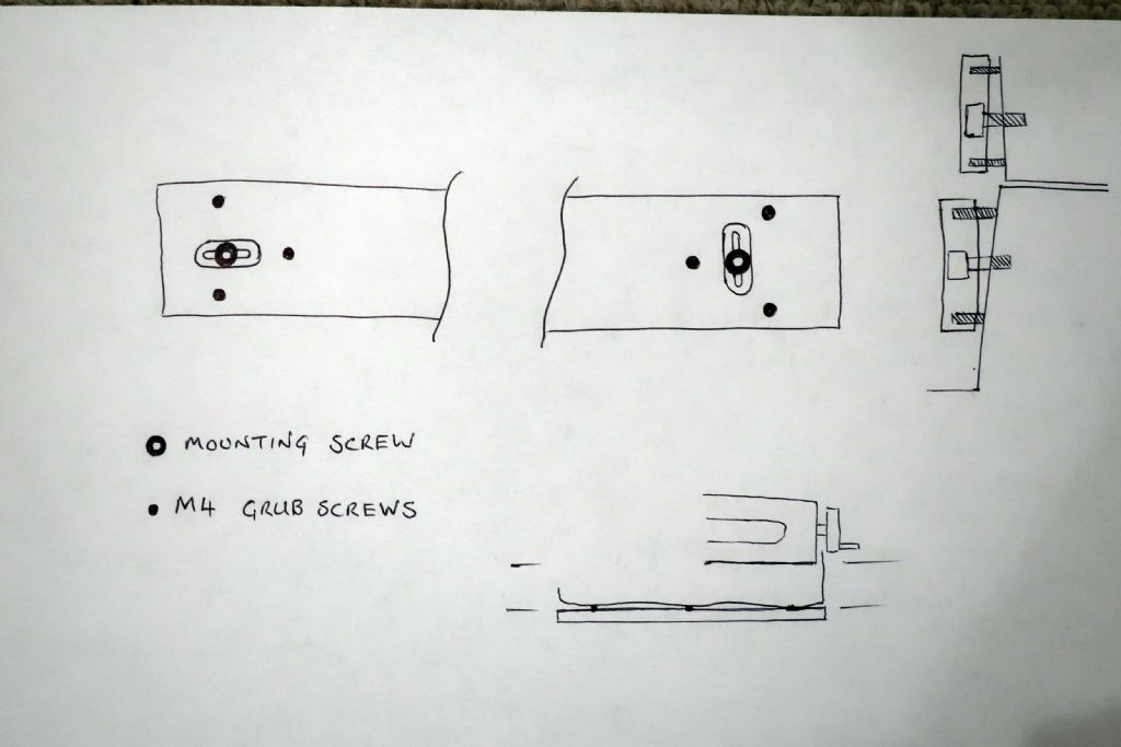
            Here's an old sketch of how I mounted the bracket for the Y-axis on the base of my mill;

            img_1567.jpg

            #602076
            Pete Rimmer
            Participant
              @peterimmer30576
              Posted by DC31k on 17/06/2022 06:18:40:

              Set it up as three points of contact with a gap behind. Clingfilm on the scale and fill the gap with JB Weld. Once set, remove the clingfilm.

              Yep, JB weld or body filler. Snug the screws up just enough to hold the scale in place.

              Or, what I have done, drill and tap to fit 3 or 4 jacking screws in a sub plate with the fixing bolts between. Yuo can then adjust the sub plate into truth and then fix the scale to that.

              #602101
              Clive Foster
              Participant
                @clivefoster55965

                +1 for the sub plate suggestion from Pete. Takes a bit of thought and preparation to clamp the plate down onto to its bed of filler so the surface that the DRO scale will mount to it true to the head movement but its all simple stuff and when done it just works.

                Jacking screws can work loose over years and shimming is even more tedious than getting a sub plate on. Thing I really don't like about those ideas is that you are working directly with a moderately expensive and not particularly strong component.

                Pushing 50 years of butting heads with lawyer Murphy and the gremlin squad has convinced me that the first thing to consider when dealing with a non routine job is "what happens if it goes wrong".

                The more money you have in the game the more important that gets.

                Clean-up and sort out assistance for the rush headed can be salutary.

                When I put the knee scale on my Bridgeport I bedded the one of the aluminium L sections out of the universal mount kit on body filler, with the aid of rather more brackets, clamps and shimmy bits than I'd expected to get it all true. To simplify clean up I lubricated the mating face of the L section so it could be lifted off after "moulding" the mating surface. I was unpleasantly surprised by just how uneven and out of line with the movements the finished surface was. Adcock Shipley did a good job of filling and smoothing their castings but the nice finish hid a surface that was, in my view, ultimately too uneven to risk direct mounting of a scale.

                Clive

                #602111
                ega
                Participant
                  @ega

                  If a true hole can be drilled in the casting then a piloted spot face cutter can be used to produce a true surface. Three of these plus fine tuning via shim washers should then suffice in many cases.

                  #602126
                  Pete Rimmer
                  Participant
                    @peterimmer30576

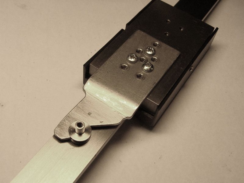
                    Here is how I did it to mount a DRO scale reader head. Four grub screws for Jacking and two bolts for fixing. Dry-fit it up then add threadlock to the jacks.

                    #602158
                    Macolm
                    Participant
                      @macolm

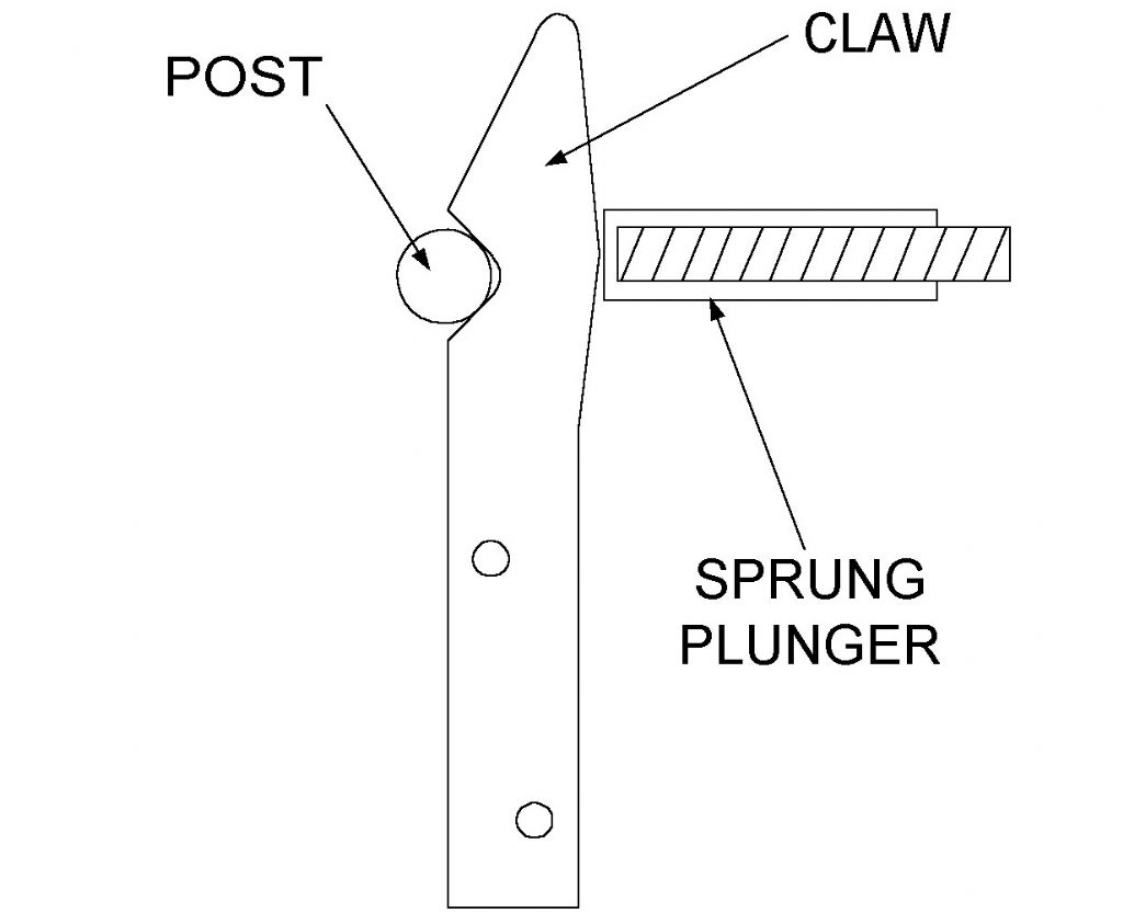
                      I have taken a different approach, using self-aligning mountings with zero backlash to avoid the risk of distortion and high operating forces. Here is diagram showing an example. It also allows the scale unit to be detached by snapping out the fixing.fig13.jpg

                      You can see how it would work in this case, needing a simple tapped hole for the post.


                      Edited By Macolm on 17/06/2022 21:28:55

                      #602404
                      Y C Lui
                      Participant
                        @yclui16187
                        Posted by Macolm on 17/06/2022 21:26:41:

                        I have taken a different approach, using self-aligning mountings with zero backlash to avoid the risk of distortion and high operating forces. Here is diagram showing an example …

                        Um…. I am afraid I cannot understand.

                        #602412
                        DMB
                        Participant
                          @dmb

                          Nor can I.

                          John

                          #602453
                          Macolm
                          Participant
                            @macolm

                            I chose a bad example, sorry about that, and will try to clarify.

                            claw and post.jpg

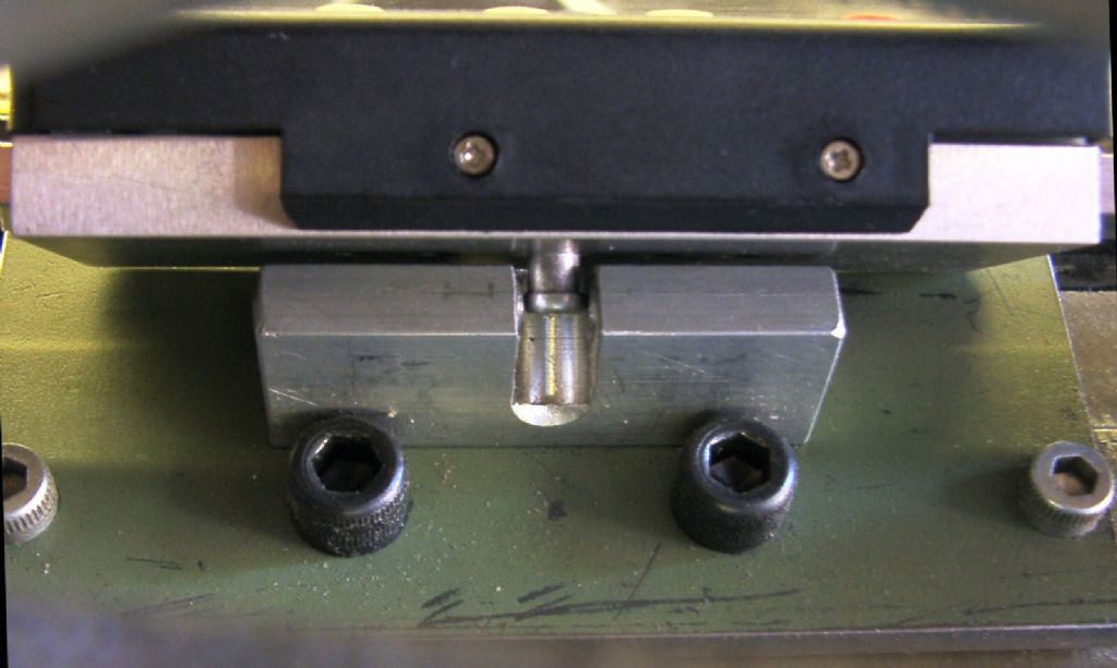
                            The claw and post image above shows the claw fitted to the underside of a display readout head with the post lying in its working position. The post only needs a single hole to fit to the machine, and it allows some freedom of movement in the other two axes, but locates the readout head rigidly along the measurement axis.

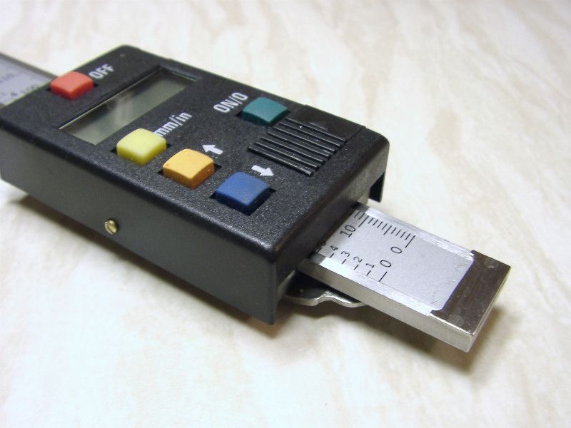
                            scale readout.jpg

                            The scale readout image above shows how this looks from the front of the readout head.


                            Unfortunately it is not possible to see this when it is assembled on the mill, because the post is intentionally fitted inside a tunnel through the mill Y axis casting. The spring plunger similarly fits in a hole so as to push the claw against the post.

                            scale fitted.jpg


                            The scale fitted image above shows how this looks from the outside, and you should be able to deduce how it is laid out. It was done like this to get it out of the way and provide some protection. It has been used successfully for more than ten years.


                            floating ref.jpg

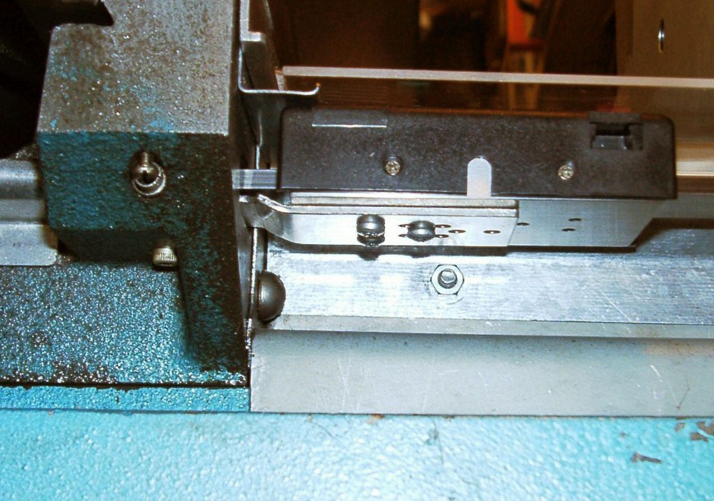
                            Another (perhaps easier to understand) example is the X axis readout head. The floating ref image above shows a spherical headed post (made from a hardened thread forming screw), fitted to the underside of the readout head. It is nipped between a fixed “anvil” and a sprung plunger, again not impeding alignment in the Y and Z axes, but having no backlash in X.


                            I hope this helps understanding the concept.

                            Edited By Macolm on 20/06/2022 14:21:19

                          Viewing 12 posts - 1 through 12 (of 12 total)
                          • Please log in to reply to this topic. Registering is free and easy using the links on the menu at the top of this page.

                          Advert

                          Latest Replies

                          Home Forums Beginners questions Topics

                          Viewing 25 topics - 1 through 25 (of 25 total)
                          Viewing 25 topics - 1 through 25 (of 25 total)

                          View full reply list.

                          Advert

                          Newsletter Sign-up