Motor wont start

Advert

Motor wont start

Home Forums Workshop Tools and Tooling Motor wont start

Viewing 18 posts - 1 through 18 (of 18 total)
  • Author
    Posts
  • #69387
    Alan Worland 1
    Participant
      @alanworland1
      I have in for repair at the moment a ‘Tauco’ pillar drill. The wiring was a mess with an extra box mounted on the back of the main ‘MEM’ switch with two extra switches and an old 5 amp socket which I presume was for a light.
      Any way it had a problem of not starting – would start if the pullies were given a push, so I stripped out the extra box/switches and wiring and in the process found a solder connection which fell apart – I thought this could be the problem, but no!
      I delved into the Delta AC Motor (1/4 hp) and found a twisted and wrapped broken wire (on the starter circuit) – still wouldn’t start
      I have since removed the centrifugal gear for cleaning of contacts etc and the thermal overload device for contact cleaning – but still no start.
      I am at a loss now, there are 3 wires from the motor coils all with continuity and the centrifugal switch can be seen and heard to work – it just wont start on its own, it needs that 1/4 turn on the pulley.
      Any ideas? I am begining to think it never worked!
      Advert
      #16657
      Alan Worland 1
      Participant
        @alanworland1
        #69390
        _Paul_
        Participant
          @_paul_
          I’m not a motor expert but could the motor need a capacitor too?, I have a 1-1/2 hp motor that uses both a centrifugal switch and 2 capacitors.
           
          Regards
           
          Paul
          #69406
          Alan Worland 1
          Participant
            @alanworland1
            How would I know?
            #69415
            Engine Builder
            Participant
              @enginebuilder

              Check inside the termial cover, sometimes there is a connection diagram there. Easily missed is you take off the cover and put it down. May not be the case but worth checking.

              Edited By Engine Builder on 30/05/2011 22:07:50

              #69417
              Dave Tointon
              Participant
                @davetointon92281
                G’Gay Alan,
                I should think that it is most likely to be a capacitor problem. I had the same thing on my ancient old pillar drill and compressor as well. . Seems capacitors have a certain lifespan.
                Regards
                Dave
                 
                 
                #69423
                Nicholas Farr
                Participant
                  @nicholasfarr14254
                  Posted by Alan Worland on 30/05/2011 21:04:22:

                  How would I know?
                   
                  Hi Alan, there may be clues to one being attached to the outside by a bracket hole or two, and/or an extra space for the wires for it, to enter into the connection box. There would be no harm in trying a suitable one. In the WPS no 16 Electric Motors by Jim Cox, 50 Mfd or more per horsepower at 240V 50 Hz are needed for start capacitors.
                   
                  Regards Nick
                  #69442
                  Martin W
                  Participant
                    @martinw
                    Hi Alan
                     
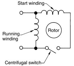
                    If there is no sign of mounts for capacitors then it could be that the motor is a split phase design unit. These do not use capacitors to start or to maintain power to a second winding. These like the capacitor start units have three wires coming from the motor which connect to the running and start windings with one end of each winding commoned together and connected to the live of the mains supply hence three wires. The start winding is connected via the centrifugal switch to the mains neutral and produces the torque necessary to start the motor. Once up to speed the centrifugal switch opens and disconnects the start winding.
                     
                    I suspect that there will be a difference in the resistance, number of windings or copper thickness, between the start and running windings but as yet haven’t found how to identify them.
                     
                    I have included a schematic of a split phase motor which may be of help.


                    Cheers
                     
                    Martin
                    PS
                     
                    The fact that the motor will run, albeit it needs to be spun up first, without a capacitor being evident supports the suspicion that it is indeed a split phase unit.
                     
                     
                    Edited By Martin W on 31/05/2011 11:04:17

                    Edited By Martin W on 31/05/2011 11:14:55

                    #69492
                    Nicholas Farr
                    Participant
                      @nicholasfarr14254
                      Hi, capacitor-start motors need a switch to cut the capacitor and start winding out when the motor has reach full speed. This is also normally done with a centrifugal switch on the rotor.

                       
                      A split-phase motor or a capacitor motor will run without the start winding in circuit, if is is spun during start up, it will run in which ever direction it is spun in. Once these motors are running, the start winding or any capacitor play no further part.
                       
                      Below is a scan of single-phase capacitor motors.
                       

                      Hope this helps.

                       
                      Regards Nick.


                      Edited By Nicholas Farr on 31/05/2011 22:54:07

                      #69501
                      Alan Worland 1
                      Participant
                        @alanworland1
                        Engine Builder, I know sometimes there is a diagram in the lid but alas not this time!
                        Dave Tointon/Nicholas Farr, I think if it had had a capacitor I would have suspected that and substituted another – but it shows no sign of one or ever being fitted to anything so it seems safe to assume one was not needed. I have a 1/3 hp motor fitted to the lathe which doesn’t use/need a capacitor.
                        Strange but when the motor is spun in either direction it will start and run in the correct direction?
                        At the next opportunity I shall measure resistance of both windings and assume the start is the lower resistance and change wiring if required.
                        For what it’s worth I could add a capacitor from another motor to the start circuit.
                        Will keep you all posted!
                        Thanks to everybody
                         
                        Alan
                        #69509
                        Nicholas Farr
                        Participant
                          @nicholasfarr14254
                          Hi Alan, you will probably find that the start winding is the one with the higher DC resistance. The best way to check which is which, is with a low voltage AC supply, say 12V @ 0.5 amps. Apply the voltage across each winding in turn with an ammeter in the circuit and a volt meter across the windings, the start winding should take the most current and have a lower voltage across the windings.

                           
                          It’s all to do with reactance and inductance stuff in AC circuits. The running winding has a higher inductance than the start winding and will draw less current than the start winding. In contrast the start winding will have a lower inductance and will draw a high current during start up, which has to be switched off when up to speed, or it will overheat.
                           
                          AC resistance isn’t as straight forward as DC resistance.
                           
                          Regards Nick.
                          #69510
                          russell
                          Participant
                            @russell
                            Its also possible that the motor is ‘poling’ (sp?), that is, the bearings have worn and the rotor is touching the stator. From (1) experience, the motor will run if given a push, but presumbly the combination of the increased friction and the disruption to the magnetic circuit/flux pattern means it cant self-start.
                             
                            regards
                             
                            russell
                            #69523
                            John Haine
                            Participant
                              @johnhaine32865
                              Motor will run either direction if it’s given a kick, this is entirely expected. Technically the single phase winding produces two equal-magnitude rotating fields, which couple equally to the rotor when stationary, but once the rotor is turning it couples more to the field rotating the same way so it starts to produce torque to make it accelerate.
                               
                              If it isn’t a capacitor-start motor, the start winding will have higher resistance than the run winding. This is so the starting current in it will be more dominated by the resistance than inductance so it will have a phase lead relative to the current in the run winding. The field produced by the start winding will therefore also have a phase lead relative to that produced by the run winding, creating a rotating field component which will drag the rotor with it so the motor starts. Once the rotor is turning the normal mechanism takes over so you can switch the start winding out of circuit (which is just as well because its higher resistance makes it hot).
                               
                              My undergrad course 40 years ago in electrical machines comes in useful just occasionally!
                              #69538
                              Ian S C
                              Participant
                                @iansc
                                In the early days of split phase motors the switch for the motor had two levers, one spring loaded, both were switched onthen let go, the spring loaded one supplied current to the start winding, no problem with centrifugal switch gear. They were usuallt nice brass and porcelane switches, I’v even seen them in anteque shops.
                                You’ll proberbly find that the start winding is wound with finer wire, and takes up a little less room than the run winding. Ian S C
                                #69568
                                Alan Worland 1
                                Participant
                                  @alanworland1
                                  Thanks for even more info!
                                  Although the motor is quite old (11/58) and has plain bearings there is not the slightest amount of wear – only a tad of end float, it spins freely.
                                  Not had a chance to ‘get out there’ tonight but I am not sure I said my previous post very well! but the motor will only run in one direction (the correct one)
                                  If the pulley is spun in the opposite direction it will come to a stop then start the other way? Might this mean that the starting process might be sort of operating?
                                  I am surprised that the start winding will be the higher resistance, but will buzz it out tomorrow.
                                  #69582
                                  Nicholas Farr
                                  Participant
                                    @nicholasfarr14254
                                    Hi Alan, the fact that if you spin the motor in the wrong direction and it stops and starts in the correct direction, does sound as if it is kind of working. This maybe mean the starting field is weak, or in the wrong place electrically, this fact could suggest that a capacitor may be needed, because it would shift the phase angle in the starting field towards to ideal position. By the age of the motor, a capacitor may not have been mounted on the motor itself originally.
                                     
                                    When you measure the DC resistance of the windings, a split-phase one will probably only have a difference of 2 to 5 ohms. If the difference is widely different say 10 to 30 ohms, it could indicate a capacitor is needed.
                                     
                                    Regards Nick.
                                    #69611
                                    Alan Worland 1
                                    Participant
                                      @alanworland1
                                      Thanks for that info Nick, but I have had a Eureka moment!
                                      After taking the motor apart once more to get at the wires there was about 7 ohms on one winding and 10 across the other, so I wired accordingly, the only difference between the wiring now is I have taken the thermal switch out of circuit.
                                      Anyway, plugged it in switched on and heh presto! it worked! repeated this several times just to check it wasn’t a fluke, after assembly of pulley, belt and terminal cover – no go again.
                                      Exactly as before, give it a spin (any way) and off it goes, but sometimes it would start.
                                      I could hear the centrifugal switch operating as the motor got to speed, but I found that if it was switched on and didn’t start the slowest of rotation would be enough to get it going, I shone a light into the motor and could see that as the motor came to a halt the start swich contacts were being ‘massaged’ and depending on where it stopped it would allow contact to be made, or not!
                                      I believe the problem is that the centrifugal part on the armature only has one point of contact with the switch ‘ring’ that it touches and therefore causes the above mentioned ‘massaging’ effect to the contacts – which have obviously worn
                                      I think the design could have been better with 2 points of contact to the switch ring to minimise contact wear – not sure if I can do anything about it easily as they appear to be spun into position!
                                       
                                      Alan
                                      #69621
                                      Nicholas Farr
                                      Participant
                                        @nicholasfarr14254
                                        Hi Alan, pleased you’ve found my info helpfull, and also that you have seemed to have found your problem. Hope you can find a solution.

                                         
                                        Regards Nick.
                                      Viewing 18 posts - 1 through 18 (of 18 total)
                                      • Please log in to reply to this topic. Registering is free and easy using the links on the menu at the top of this page.

                                      Advert

                                      Latest Replies

                                      Viewing 25 topics - 1 through 25 (of 25 total)
                                      Viewing 25 topics - 1 through 25 (of 25 total)

                                      View full reply list.

                                      Advert

                                      Newsletter Sign-up