Motor speed control
Motor speed control
Home › Forums › Hints And Tips for model engineers › Motor speed control
- This topic has 24 replies, 10 voices, and was last updated 8 April 2014 at 09:51 by
 Neil Wyatt.
-
AuthorPosts
-
28 March 2014 at 20:44 #30484
Andy Ash
Participant@andyash2490228 March 2014 at 20:44 #148332Andy Ash
Participant@andyash24902A couple of weeks back there was a thread here all about electronics. In particular motor control. Various schemes were discussed but a common suggestion was that something like an Arduino could be used to generate PWM to control a motor. Understandably, many model engineers are not very keen to enter the electronics realm, let alone software. Vive la difference!
Over the years I have seen many threads talking about inverters and reversing switches for single and three phase motors. Sometimes I have been frightened by some of the things that I have read. This is especially because high power switchgear is not a good place to do learning. Often, fault finding and problems are posted. You know that if you were there in person it would be a simple fix, but without your own eyes and ears it is just too hard to diagnose. Often it seems that posters want to know which colour wires to connect, as if there is some universal standard. I wish there were.
I wanted to put up a really simple speed controller, that anyone could have a go at, in complete safety. One which could still be useful if needed. What I'm going to post might create a fire if you get it wrong, but it cant shock you so badly that you will be unable to put the fire out! Look on the bright side, I say!!
Actually this controller can be quite powerful. It runs from a 12V supply and is rated for at least 50amps. That gives you 600watts, nearly 1hp. You might find a motor to do that from 12V, but you're less likely to find a power supply which will deliver 50amps. My recommendation is to use a car battery as an accumulator, and set it up with a trickle charger. In the workshop environment you can drape your 12V power cable across a machine tool and not worry too much about electric shocks. Perhaps it could be good for gear hobbing or tool post grinding. It doesn't even have to be a motor, it could be a heater or anything really. That's up to you. Do use cables which are up to the job! If you don't they'll get hot and melt.
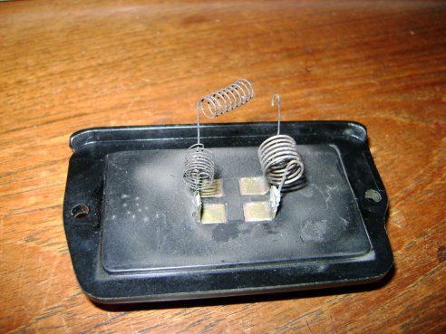
The reason I did this thing was that I remembered my demister fan in the car had not been working properly for ages. The two slow speeds didn't work, but the fastest and the next fastest did. I had a good idea that it was the dropper resistors that had failed. I also had the idea that I could make a speed controller to replace the resistors. The picture below shows the faulty resistance wire.
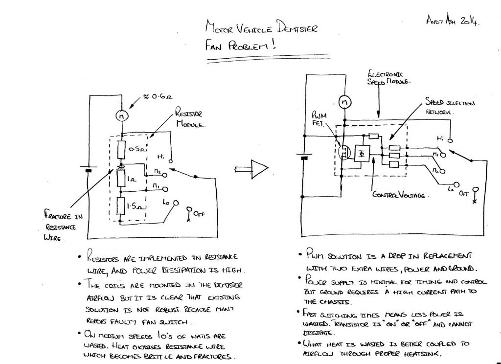
The module has three resistors chained and tapped. The diagram below shows the electrical arrangement.
The resistors project into the airflow from the fan. It's a great idea, the fan cools the resistors that control its speed….. The problem is that the resistors make more heat when the fan goes slowly, and so cools less. They could have rated them properly in design, but evidently they didn't.
The great advantage of a PWM speed controller is that it is much more efficient than resistors. With the resistor scheme, perhaps the motor runs at half speed. The effective resistance of the running motor is the same as the dropper resistor. Half the energy goes to the motor, half to the resistor. I measured the running current on the next to fastest speed and found 9 amps. That's 40 watts of power wasted to go at half speed. The heat has to go somewhere and that is why the resistors burn out, as so many people find. Hot in the airflow, the resistor wire oxidises readily and becomes brittle. Cars vibrate and demister fans fail regularly.
28 March 2014 at 20:45 #148333Andy Ash
Participant@andyash24902With the PWM scheme the transistor is either on, or off. When on, its resistance is just a few milliohms. When off it is tens of megohms. In both situations the transistor cannot dissipate any power as heat. The only time it can actually make heat is during switching. It switches so fast that this is very little of the overall time.
By varying the relative quantity of time the motor is switched on, against the time that it is off, the overall amount of electricity that passes through can be varied. This works especially well on a motor. Much of the energy that is in a motor is stored magnetically. The magnetic field in the motor can act like an electrical spring. As the transistor switches on and off the magnetic field takes up the electrical slack keeping the motor revolving.
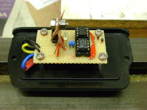
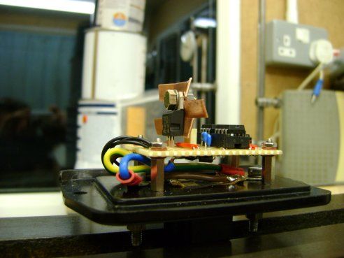
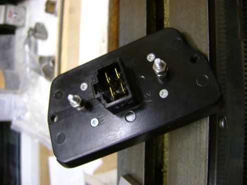
The diagram above shows the solution I devised as a drop in replacement for the resistor module that failed. It needed new power supply connections because the old resistor block had no active electronics. I just drilled some holes through the bakelite plate and used 4BA screws, nuts and washers. I pulled the new power supply out of the car wiring loom. The ground is a screw into the car chassis, and the power comes from the battery side of the fan motor.
The existing connections to the fan switch were reused. The airflow continues to provide cooling for the transistor. It turns out not to be needed. The transistor doesn't even get barely warm.
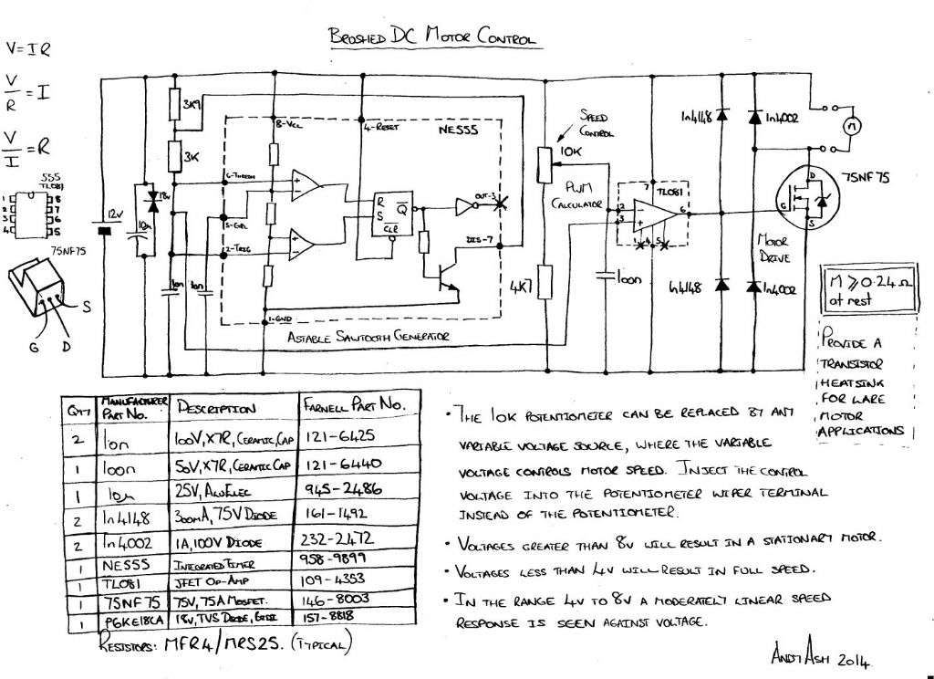
The solution uses a 555 timer to generate a saw tooth waveform with a voltage between 4 and 8 volts. The Op-Amp compares the speed control voltage with the 555 timer saw tooth generating a variable pulse width square wave with fixed frequency. Normally one might use a comparator to do the voltage comparison. Here I used an Op-Amp. The transistor has a high gate capacitance. It needs to be driven high and low. If it isn’t the gate voltage dwells at an intermediate voltage. When so, the transistor dissipates power as heat. Comparators usually have open collector outputs and these require a pull-up resistor. Such a pull-up can only charge the transistor gate at a given rate, which causes the unwanted dwell. In this situation using an Op-Amp as a comparator is advantageous.
That's pretty much it. The pictures show the final solution which I installed in the car this evening. If you need to find a good, powerful, cheap 12V motor, you could do much worse than go to a car scrap yard. This controller, using the components specified, should be capable of a 600W nominal motor. The fan in my car appears to be about 240W and that is just fine.
The parts will cost pennies. Maybe you could try it and see how far you can make it go. The part numbers are all Farnell. I'd be interested to see anything that people might use it for. I don't know that I have time to support any problems that people have. Rest assured that if you make the circuit I drew, it will work. Mine certainly does. As usual, I had to find out the hard way, that it won't work if you make something different from the plan initially!!
29 March 2014 at 09:24 #148362Chris Jones 3
Participant@chrisjones3Hi Andy, Nice circuit, can I suggest that the control voltage that can be connected in place of the pot slider is limited with a 1K series resistor and a couple of 1N4148 diodes to supply rails, to keep the voltage on the TL081 input pin within its absolute maximum ratings (just in case). The TL081 has such a high input resistance that wires can pick up large transients from motors etc.
The components can also be obtained from CPC (a sister company to Farnell), and at the moment internet orders are postage free with no minimum order value.
Chris.
29 March 2014 at 15:55 #148392Andy Ash
Participant@andyash24902That's a really good point Chris.
As you say, if the control voltage comes from "somewhere else" there are no guarantees about limits.
The TL081 won't be happy if the control voltage goes outside of the voltage rails, and this is true even if noise and transients cause the excursion on an otherwise compliant signal. The limiting resistor and diodes will give a good measure of protection.
The TVS (transient voltage supressor) diode seems to be quite important. The design started out without one. The 555 has an 15 volt PSU limit. I popped a couple of them when I externally disconnected the power with the motor running. Obviously the timer operates quite close to its voltage limit and the extra "lump" from the stopping motor is too much.
The TL081 has a +/- 18 volt (36 volt) limit and it never gave a problem in the same situation.
With the TVS diode added the problem with the timer vanished.
If you're going to do motor control with this circuit I would recommend the TVS diode strongly.
Edited By Andy Ash on 29/03/2014 15:57:50
29 March 2014 at 16:46 #148398 Neil WyattModerator@neilwyatt
A nice circuit taht could be used in many situations.
May I suggest an LM311N comparator instead of the op-amp? It will switch faster (200ns as against about 1 uS for the op -amp at 12) and it can take input voltages up to 30V above the negative rail.
Don't forget you'd need a pull up resistor (say 1K5) on the output as it is open collector.
Neil
29 March 2014 at 17:45 #148403Les Jones 1
Participant@lesjones1Hi Neil,
Andy states in his second post that he chose to use an op amp instead of a comparator as its output has active pull up as opposed to open collector. I think I would have used a comparator followed by a transistor stage to give active pull up.Les.
29 March 2014 at 19:24 #148410Andy Ash
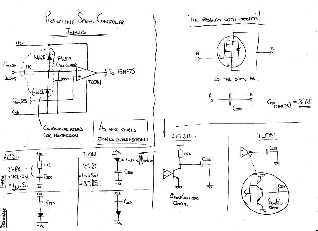
Participant@andyash24902I did another diagram to assist the explanation;
It shows the extra components that you would want if you were introducing your control voltage from another circuit, rather than using the potentiometer shown in the schematic.
The other part of the diagram is an attempt to show why I decided to use the TL081 rather than a comparator like the LM311.
These big MOSFETs are really great at controlling lots of power from very simple low power circuits. But the problem with them is that they have very high gate capacitance for a transistor. I explained how they have a very low on resistance and a very high off resistance. This is really important to their ability to control big power from little circuits.
You just cant use them linearly.
If you have a transistor like this "half on", but all of the time, then in a 600 Watt circuit it will have to get rid of 300 Watts. That needs a heatsink with its own fan, perhaps the size of a couple of bags of sugar. If it is fully on 50% of the time, it still only passes half the power, it might only dissipate a single watt. Only a small heat sink is required.
The rate of change between on and off determines exactly how much heat the transistor will need to emit. The faster the better. With the pull up on the LM311 the time constant (the time to reach only 63% of the final value) is 4 microseconds.
The 555 timer is set up to give about 14KHz , you could go higher if you wanted. 4 microseconds is more than 5% of that cycle time, which is too slow.
The TL081 with its push pull outputs has a much lower output impedance. I've said on the diagram, nominally 1 milliohm, but it isn't that good. The exact value is debatable, but it will be much better than the 1k2 ohm pull up resistor.
If you had to use the LM311 then you would be better off using an external buffer made of transistors. Even then making normal bipolar transistors move out of saturation quickly is quite hard to do. I would probably recommend schottky diodes on the transistors. Perhaps better still a LS TTL buffer, but it is another chip.
Normally the TL081 would not be good to use for driving a capacitor directly. Especially using negative feedback. The datasheet for the TL081 warns against it. There would likely be stability problems and the amplifier would struggle to drive the capacitor. Certainly that would be true with a big capacitor tied directly to ground.
Here, although the gate capacitance is higher than we would like, it isn't *big* in electrical terms, and more importantly the amplifier is being used open loop. I think that is why it works out quite well.
Edited By Andy Ash on 29/03/2014 19:29:46
29 March 2014 at 19:36 #148412John Haine
Participant@johnhaine32865I can't understand why you are using a 555 and a comparator when there is a standard 555 circuit that does speed control on its own (with an external MOSFET) available ready built on a pcb from Maplins.
29 March 2014 at 19:52 #148416 Neil WyattModerator@neilwyatt
Point taken Andy; although as the LM311 has a slew rate of only 8-16 V/uS so at 12V it will take about 1uS to go from low to high even with an open loop so I suspect it takes a lot longer than 3.7ps to switch the transistor!
> why you are using a 555 and a comparator
To allow an external control voltage to be used, I assume.
Neil
29 March 2014 at 20:06 #148419Andy Ash
Participant@andyash24902There were a couple of reasons for doing this really John.
The first was that I had all the bits in my parts bin. The idea came when someone was asking about motor control on this site a couple of weeks back.
In between, I remembered the problem with my car and thought I could kill two birds with one stone!!!
I had to fit the thing on the back of the bit of bakelite so I guess I would have ruled out the idea of using a pre-made circuit. The truth of it is that you can get this kind of widget on e-bay, made freshly in Chinese tin shack, shipped around the world by airfreight.
I guess you could buy a two stroke diesel, or a tin plate steam engine, from china but nothing beats knowing and being able to make it yourself.
I suppose the final thing is that if you want to do something like this, especially closed loop speed control, you would have to combine different circuits to control the motor. If the only option is an open loop speed controller from maplin, then the box you put it all in is getting quite big. That's the thing with integration.
Maybe if I get time, I'll find a motor and make the hardware to do the full closed loop speed control. That, actually was the original thread that sparked my interest a few weeks back. The request was to have two motors running at the same variable speed from one controller, irrespective of load.
This isn't the whole deal I grant you, but it is a part of that, and at least I made a bit of a try.
Edited By Andy Ash on 29/03/2014 20:07:01
Edited By Andy Ash on 29/03/2014 20:07:50
29 March 2014 at 20:59 #148430Muzzer
Participant@muzzerThe original question was how to get 2 motors to turn at the same speed. At some point you are going to have to either acquire some measurement of the actual individual motor speeds and use a closed loop to try to get them fairly close, or you are going to have to use a motor + drive system that will faithfully deliver what you ask ie feed forward.
The first (servo) solution will require significant effort to get it anywhere near the requirement and you are some way from that right now. The second is relatively simple if you implement a stepper motor + drive for each motor and provide them both with the same direction and step signals. School children around the world are doing this as we speak and the parts are not surprisingly readily available. You can even play about making your own drivers if that is your thing.
I agree it's fun to mess about with electronics and make stuff rather than buy it ready made but there needs to be some plausible path to the end goal?
I don't know how old your car is but they have been using PWM in car HVAC fan control for years…..
Murray
29 March 2014 at 21:21 #148431Anonymous
When designing a MOSFET gate drive circuit the capacitance parameter Ciss is largely irrelevant. It is a small signal parameter, normally measured at 1MHz and zero gate voltage. What is important is Qg, the total gate charge. This parameter is the charge that needs to be injected into the gate to turn the device on, and reach a specified gate voltage. For the device specified the maximum Qg, for a gate voltage of 10V, is 160nC. But Q=CV so in an idealised world that gives an input of C=16nF.
Also Q=it, so if we need a gate charge of 160nC and we want to switch in 1µs then we need a current of 160mA for that microsecond. To turn the device on we need to drive that current into the gate, to turn the device off we need to pull that current out of the gate. The TL081 is a venerable device with a correspondingly old-fashioned datasheet, which makes it difficult to estimate the output current capability. However, there's no way it's going to supply anything like 160mA. There is a graph of peak output voltage versus load resistance in the datasheet, from which I estimate it would supply on the order of 20-30mA.
Switching speeds for power devices are determined by both 'static' losses and dynamic effects. For this simple circuit turn-off is more important than turn-on. At turn-on there is no current flowing, so little or no dissipation in the device. The main problem will be negative dv/dt on the drain. This will feed through the drain-gate capacitance and oppose the gate drive, trying to turn the device off. For turn-off, when substantial current may be flowing, there are several issues to consider. First, as has been stated, during turn-off current will be flowing as the voltage across the device rises, and this causes a 'resistive' loss in the device. For power devices this can be substantial (I'm talking here of devices switching hundreds of volts and hundreds or thousands of amps). During turn-off we also have two dynamic effects. First, the voltage on the drain is now rising, which when feed through the drain-gate capacitance will try and turn the device back on. When driving large power devices the gate is often taken negative to counteract this effect. Second, the drain current will be changing so we have di/dt effects creating voltages on the drain, according to the amount of inductance in the drain circuit. For power devices switching hundreds of amps per microsecond you don't need much inductance to get hundreds of volts. Even a few inches of wire will do.
Regards,
Andrew
29 March 2014 at 21:45 #148432Andy Ash
Participant@andyash24902Actually I did look to see if I could get a direct replacement for the car and I can. The car in question is of 1998 vintage. It's a British made Honda/Rover, but the ancilliaries are Valeo – French.
Maybe you were suggesting I am a bit chavvy. I accept it all!!!

They still make modern cars with resistors to slow the fan down I think, but from what I saw they now enclose them in an aluminium finned can. I guess by shielding the resistance wire from the airflow and spreading the heat out over a larger area the tendency to oxidise is reduced. There were no parts like that for my car. I had a choice of a direct replacement, but I'm happy with my bodge.
Obviously the advantage of having a current controller like this one is that one timer can be used to do current control for two motor channels. Double up the Op-Amp and transistor to get two channels. If you use a dual Op-Amp it is still a two chip solution, although you have an extra transistor.
Then you have some sort of pulse generator on the motor shaft, and use another dual amplifier to integrate the pulses. If you make the dual integrating amplifier into a quad amplifier, then you have two additional amplifiers to use as error amplifiers.
That's still only a three chip solution but it pretty much does the full deal.
Getting the loop stable is a bit of an issue, but built up on breadboard as a prototype, you hack and bodge to your hearts content!! It's not beyond the wit of man and it's not that much more.
I don't know what the original application was, but here we are approaching the capability to do perhaps 10,000 rpm, and possibly 600W. I know of no stepper that will do that.
I did wonder what the application might be.
I was thinking it could make quite a good RC hydroplane. The motors could be in pods at the front with a water screw and fixed distance between, and you would have thin wire trailing out behind to keep some directional stability.
With the electronic control scheme it would be easy to have one control for speed, and another more delicate one for direction.
Just a thought.
Edited By Andy Ash on 29/03/2014 21:51:46
29 March 2014 at 22:27 #148436Andy Ash
Participant@andyash24902Posted by Andrew Johnston on 29/03/2014 21:21:07:I cannot disagree with your thesis.
I do notice that you do not consider the shape of the voltage curve as the FET charges through a 1K2 pull-up resistor. I think the idea that most of the time to reach a target voltage occurs after the 63% time interval leads me to conclude there would likely be significant resistance effects during turn on using an open collector comparator.
I've not done many sums for this. Actually, I didn't do any, but I'm not ashamed of that.
The only thing I would say in contention with what you have said, is that your assesment and conclusions lead down the path of designs that use many more components than this one. I don't think that is any more the right answer than what I have suggested here, or the other alternative which might be a pre-designed mosfet driver chip.
I didn't actually measure the edge speed. It looked fast enough on the scope, but my scope is a bit crap. I did decide before drawing it up that an LM211 which I have in my parts bin wasn't a good candidate. All I really know is that it didn't get hot and it doesn't seem to die no matter what I do now.
I think someone ought to show if the LM311 makes any difference or not. I'm not going to, but I do think that it is easier to be critical than creative.
I didn't do vibration and environmental testing, but I don't think that the original resistors got that kind of attention either. I am interested to see how long it lasts…. If you're nice to me I'll be honest about it!!

If anyone is worried at all, you can always buy the Chinese one on ebay!!
Edited By Andy Ash on 29/03/2014 22:31:55
30 March 2014 at 09:08 #148440 Neil WyattModerator@neilwyatt
I wouldn't fret
Andy, there are 101 ways to skin a cat in electronics as much as engineering. Lots of folks have said 'just use a 555' but you are the first here to bother actually designing such a controller!
My most recent motor controllers use an AVR microcontroller and logic-level FETs. I use heatsinks, but I suspect they are pointless.
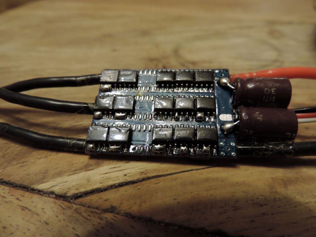
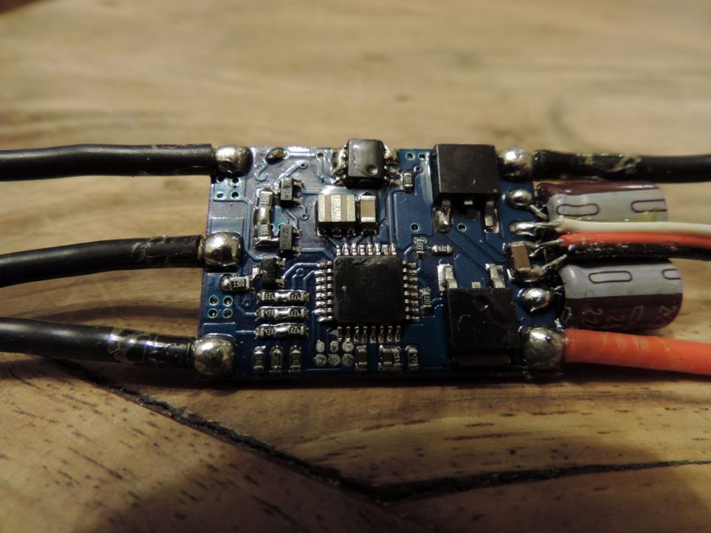
The ebay option isn't always ideal. Below are two pictures of a BLDC speed controller for a model multi-step hydroplane. It appears to have been soldered by a drunk gorilla in a straight jacket. Believe it or not, it works!
Neil
30 March 2014 at 13:35 #148454Gordon W
Participant@gordonwIt might well have been my post that has started this thread so some slight updates.- The devices shown here are the sort of things I was looking at. I've decided to couple the two motors mechanically and except any small losses. I will print out the hand drawn diagrams ( and blow them up) I find most of the above discussion to be beyond me but reckon I can follow the drg. At least I will know a bit more and if it all goes wrong nothing much is lost.
30 March 2014 at 20:39 #148484Anonymous
Out of idle curiosity I fired up my experimental ignition circuit this evening. This uses a MOSFET instead of contact breakers to create a high voltage (via di/dt) from an inductor. For an ignition circuit we don't really care about turn on, so this is done with a 12k pullup to 12V. We do care about turn off, the faster the better, so this is done with a npn transistor used as a crowbar between MOSFET gate and source.
The MOSFET I am using has a Ciss of 1490pF and a total gate charge of 52nC. So using our rule of thumb that the capacitance derived from gate charge is around 4 times the value given by Ciss we get approximately 6nF. With a 12k pullup that gives a time constant of 72µs. Five times that is 360µs. In practice the MOSFET turn on is rather faster than 360µs, about 150µs, as shown below (top trace is the square wave gate drive and lower trace is on the MOSFET gate:
Note the little kink in the turn on at about 5V. If you look at the gate charge characteristic on any MOSFET datasheet it will be clear why the kink is there.

Here is the turn off:
Much faster, as it is an active turn off, but the little kink is still there!
Finally, here's the drain voltage:
Peak voltage is about 900V, not bad from a 5V rail and about 100µH. In fact the MOSFET drain-source is avalanching and breaking down. But don't worry, it's an avalanche MOSFET so it is designed to withstand repetitive avalanche breakdown. As they say in films, no harm was done to any MOSFETs during the making of this post.
One issue that hasn't been mentioned is that the TL081 output falls short of the power rails by several volts, depending upon the load. That means that there is a good chance that it may not be turning the MOSFET properly off.
Regards,
Andrew
30 March 2014 at 21:14 #148488Oompa Lumpa
Participant@oompalumpa34302I have a couple of these – as new – if you want to try something different:


graham.
31 March 2014 at 13:06 #148531Billy Mills
Participant@billymillsGood job that this is only a heater application. After some time you can expect the mosfet leads to fracture. Putting an unsupported bit of copper on the mosfet makes matters considerably worse by increasing the mass and putting the resonant frequency closer to the peak range experienced in a vehicle. It does not take much to do the job properly, bolt or solder the mosfet to the board. Even a blob of epoxy around the leads will help a bit but firm fixing is better.
The use of I.C. sockets is inadvisable in a vehicle especially if the assembly is bulkhead mounted. Sockets are a real liability, the only reason to use sockets is where the designer is unsure that the design is sound, it makes changing damaged devices easier. I would also point out that there is no parasitic prevention which is a real issue with unspecified loads, and some mosfets, it would cost a penny to place a 22 ohm resistor in the gate.
Billy..
31 March 2014 at 13:21 #148532Billy Mills
Participant@billymillsMust also point out that the magnetic field does NOT keep the rotor turning, That is simply rotational kinetic energy. The magnetic field in a PM motor induces eddy currents in the rotor iron which hinders rotation, that is why the wound armature is not solid iron but laminated to minimise these losses. You can get ironless armatures- moving coil or "printed circuit" motors- especially for high acceleration servo applications. These motors have absolutly no iron in the armature apart from the drive shaft.
Billy.
7 April 2014 at 21:19 #149183Andy Ash
Participant@andyash24902Sorry about the delay, I got bound up in contracts, accounts, insurance and all manner of red tape this last week.
@Neil Wyatt – Looks like a driver for a brushless three phase pm motor to me. My humble little circuit does nothing so bold. I was actually trying to eliminate the microcontroller so that might explain something. In the back of my mind I have a scheme for a three phase motor that doesn't involve a uController. The interesting thing is that the uC implementation for three phase drive is simpler than without the micro(unless you use transformers which are hard to obtain but could be home made). For the simple switching regulator it's the other way about; the uController DC switcher is more complicated. I actually wonder about using a five pin switching regulator in an SOT23-5 package as a variable speed controller for a small motor. Instead of two 8pin DIL chips and a transistor, it becomes one SOT.
I guess if the components don't fall off, and the electrons can get through, it doesn't really matter what the smouldering looks like. I think perhaps if some of the pins are high current, it could be that the extra solder helps. Who knows, there's no schematic, so I'm just guessing.
@Andrew Johnston – I figure that the achievable peak voltage for your boost regulator is mostly about the size of the inductor you use, as long as the transistor is up to the job. In the end, an automotive ignition coil is quite a useful weapon for high voltage work, making things work well with small inductors is real magic.
If you need high current at high voltage, sometimes a microwave oven transformer is quite the tool. Generally though the microwave oven transformer is starting to get a bit deadly. I would always recommend using that along with some sort of current limit. I might even be able to attribute my current survival to such a circuit!!! There are quite a few designs for Geiger Muller tube drivers out there. I think they are often achieving 5-600 volts with very small circuits and components.
It's the making and doping of the tubes which I think is the really interesting bit.
7 April 2014 at 21:20 #149184Andy Ash
Participant@andyash24902@Ooompa Lumpa – That looks like an interesting kit. Mains oriented, so perhaps a bit iffy for kids, but handy none the less. Obviously no schematic, so no idea how it works except that it seems like it's for an AC supply and that makes me think that the big device might be a Triac. The general triac circuit is different from the circuit I posted. If it's a triac it uses the frequency of the mains supply to regulate the switching time intervals. I've not got the specifications for the device (I don't know what it is) but I'd make a guess that you would need a pretty big heatsink to get the full 1kW out of that circuit board.
It is important to understand about heat developed in an AC motor. You can slow an asynchronous motor by starving of current it and increasing the slip angle, but the thing really wants to rotate at the line frequency. It might be slower if you starve it, but it'll get hot and hungry. That's the typical lathe motor, a squirrel cage.
For those a VFD is a much better bet. Although the circuit I posted would not operate at mains voltage, the same idea and different components works. Actually the basic scheme is to apply an AC voltage to the speed control input, using some isolation and a transistor capable of withstanding a higher voltage. The AC voltage input represents what would have been the line frequency. By varying the frequency, the motors varies its speed with only a transitional slip angle. The motor then does not need to get hot just to run slowly. The only thing to watch for is that it can still develop heat when loaded, and the fan may not run at the same old design speed.
I think the old style B&D or Wolf drills, were AC/DC brushed motors. I think maybe a modern SDS drill would be that way too. These are slightly different because they don't need to run hot, to run slowly at any frequency. The trouble is that they are not speed constrained. The typical universal motor will free run at high speed. The smallest of loads will lower the speed dramatically. Although the triac gives scope to change the speed of a universal motor it cannot be said to control the speed. I suggest the only way that would work properly is to close the loop, and monitor the speed electronically. This is an especial problem with grinding wheels which should run at a specific speed.
Given that the list seems slightly hostile I will say that it is true that a DC motor with a switching controller like I drew will allow the speed of its motor to vary if it is loaded. I think there is no comparison between this small speed change and that of the series wound universal with open loop speed control.
@Billy Mills – I'll be honest it's a "knock it together" to put it into the car. I doubt that the car has more life than my dodgy speed controller. I said before that someone might want to use it for their purposes, but I've not described how to assemble it. You might put it in a box, or make a circuit board for it. You might pot it up and put it into your aerobatic demonstrator. That's up to you, but I do understand that you don't like the way I put mine together.
I guess I figure it like locomotive drawings. You get loads of advice on how to make a combination link, but no-one will stick their neck out and draw one up. I think that's a shame, but I can begin to see why, even on just this thread.
Surely if you open the DC motor electrical circuit, then the back emf begins to fall along with rotor speed. When the circuit is closed again with the same driving emf, a higher current flows than when the circuit was opened. The increase in current brings the speed back to some sense of equilibrium based on the "on time". The current begins to fall as the rotor speed increases and the back emf rises, whence the circuit opens again.
To my mind (however incorrect you feel I am) that is what is happening, and it is why the motor continues to rotate, even when loaded. For a given "on time" the initial current is higher when the motor is more greatly loaded. The changing magnetic field encourages the dynamic variation in current. The field stores energy like a spring. The spring relaxes differently depending on the loading. I suppose it depends on how one would view a motor. Perhaps it is a rotating mechanical thing with an electrical supply. On the other hand it might be a magnetic couple between an electrical and a mechanical system.
Edited By Andy Ash on 07/04/2014 21:22:48
Edited By Andy Ash on 07/04/2014 21:24:48
7 April 2014 at 22:26 #149187John Haine
Participant@johnhaine32865A dc motor run from a duty cycle speed controller keeps going between pulses because of its momentum, nothing to do with magnetic field. It generates a decreasing back emf as it slightly slows, so when the controller switches back on the current is as you say slightly higher than just before it switched off.
a triac controlling a motor is either fully on or off. When it's on all the applied volts is dropped across the motor except for a small drop a volt or so across the triac, so only a small power is dissipated in the device. When it's off the current is just a small leakage and all the volts is dropped across the triac so again the power dissipated is small. So the size of the heat sink is not that dependent on the controllable load.
8 April 2014 at 09:51 #149231 Neil WyattModerator@neilwyatt
Yes Andy,
It's a cheap radio control BLDC speed controller, because I didn't want to cough up from an Mtroniks one or spend ages making one for something that will probably only get used once every year or so.
> I think perhaps if some of the pins are high current, it could be that the extra solder helps. Who knows, there's no schematic, so I'm just guessing.
I found the datasheets for what I think are the mosfets, and the blobbed pins are commoned inside the chips. My guess is that they fail a check after the surface mount oven and go in a bin. Someone buys them up really cheap, blobs on solder then tests again. I might clean off the varnish and try a proper rework on the board – which will then cease to work.
Neil
-
AuthorPosts
- Please log in to reply to this topic. Registering is free and easy using the links on the menu at the top of this page.
Latest Replies
Home › Forums › Hints And Tips for model engineers › Topics
-
- Topic
- Voices
- Posts
- Last Post
-
-
Chester DB10LB Lathe – Not starting
Started by:
David Deaville in: General Questions
- 3
- 5
-
6 April 2025 at 13:34
David Deaville
-
Supply company catalogues
Started by:
nevillet in: Workshop Tools and Tooling
- 5
- 8
-
6 April 2025 at 13:23
 JasonB
-
James Coombes Drawing Error (or mine?)
Started by:
Steve Withnell in: Drawing Errors and Corrections
- 5
- 7
-
6 April 2025 at 13:16
 JasonB
-
Measuring increments on boring head
Started by:
Bill Phinn in: Workshop Techniques
- 15
- 21
-
6 April 2025 at 12:46
 Julie Ann
-
Steam pressure using thermistor
Started by:
michael howarth 1 in: General Questions
- 2
- 2
-
6 April 2025 at 12:25
Andrew Tinsley
-
Machinery Handbook
1
2
Started by:
Dalboy in: Books
- 31
- 40
-
6 April 2025 at 12:03
 Michael Gilligan
-
Which type of single phase motors are best for constant use – power hacksaw
Started by:
ell81 in: Beginners questions
- 5
- 5
-
6 April 2025 at 11:44
Clive Foster
-
Flattening brass plates
Started by:
t1krt in: Workshop Techniques
- 6
- 7
-
6 April 2025 at 11:03
 Dave Halford
-
Stripped aluminum threads. Now what?
1
2
Started by:
brucemc777 in: Beginners questions
- 19
- 35
-
6 April 2025 at 10:39
howardb
-
Problem getting the right parameters on a VFD
Started by:
Robert Graham in: Electronics in the Workshop
- 7
- 9
-
6 April 2025 at 10:26
Robert Graham
-
Damp proofing concrete floors
Started by:
Duff Machinist in: General Questions
- 13
- 14
-
6 April 2025 at 02:52
Duff Machinist
-
Elliott Omnimill Quill Clamp
Started by:
dangermouse in: Manual machine tools
- 4
- 5
-
5 April 2025 at 20:27
Paul Kemp
-
How to wire up 3 phase motor and 3 phase converter?
Started by:
ell81 in: Beginners questions
- 7
- 15
-
5 April 2025 at 18:36
 Robert Atkinson 2
-
Morse Key
Started by:
Steve Withnell in: Work In Progress and completed items
- 3
- 3
-
5 April 2025 at 18:20
Mike Hurley
-
My week this week! My workshop videos
1
2
…
11
12
Started by:
Phil Whitley in: The Tea Room
- 14
- 286
-
5 April 2025 at 16:00
Phil Whitley
-
Myford S7 Taistock Adjustment
Started by:
 Harry Wilkes
in: General Questions
- 9
- 12
-
5 April 2025 at 15:17
 Harry Wilkes
-
Flexispeed Meteor 2
Started by:
ferroequinologist in: Manual machine tools
- 11
- 19
-
5 April 2025 at 07:01
ferroequinologist
-
What Did You Do Today 2025
1
2
3
4
Started by:
 JasonB
in: The Tea Room
- 23
- 78
-
4 April 2025 at 20:57
Nigel Graham 2
-
Powered hacksaw – blade lift for the return stroke
Started by:
 Sonic Escape
in: General Questions
- 8
- 17
-
4 April 2025 at 20:00
 Nicholas Farr
-
New member old lathe
Started by:
t1krt in: Introduce Yourself – New members start here!
- 8
- 16
-
4 April 2025 at 19:52
t1krt
-
Tangential tooling
1
2
Started by:
Keith Matheson in: Workshop Tools and Tooling
- 13
- 29
-
4 April 2025 at 18:14
Howard Lewis
-
Which lathes have drawbars in the headstock?
1
2
Started by:
ell81 in: Beginners questions
- 17
- 26
-
4 April 2025 at 18:04
Howard Lewis
-
gear cutting with the shaper
Started by:
jacques maurel in: Workshop Techniques
- 5
- 6
-
4 April 2025 at 15:15
Andrew Tinsley
-
Electric motor vibrations
Started by:
 Sonic Escape
in: General Questions
- 8
- 12
-
4 April 2025 at 07:38
 JasonB
-
Build Your Own Metal Working Shop From Scrap (7 book series)
Started by:
Dr_GMJN in: Books
- 6
- 7
-
4 April 2025 at 06:39
Pete
-
Chester DB10LB Lathe – Not starting
-
Latest Issue
Newsletter Sign-up
Latest Replies
- Chester DB10LB Lathe – Not starting
- Supply company catalogues
- James Coombes Drawing Error (or mine?)
- Measuring increments on boring head
- Steam pressure using thermistor
- Machinery Handbook
- Which type of single phase motors are best for constant use – power hacksaw
- Flattening brass plates
- Stripped aluminum threads. Now what?
- Problem getting the right parameters on a VFD


