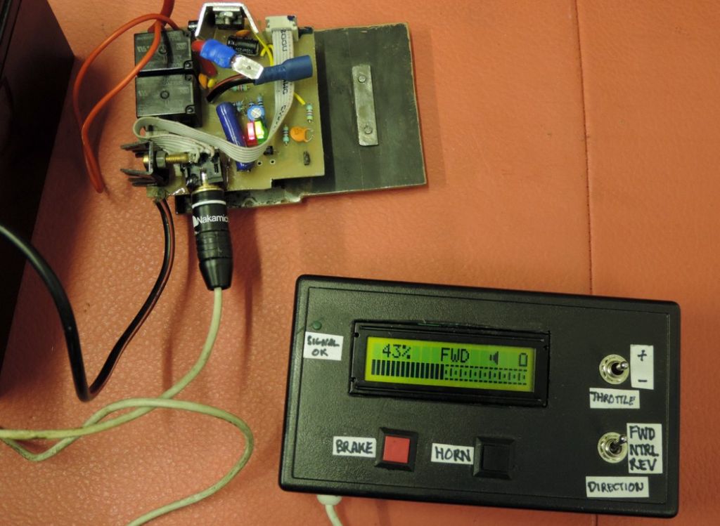
Motor Controllers for Models and Tools
Motor Controllers for Models and Tools
- This topic has 32 replies, 10 voices, and was last updated 6 June 2014 at 18:21 by
 Neil Wyatt.
- Please log in to reply to this topic. Registering is free and easy using the links on the menu at the top of this page.
Latest Replies
Viewing 25 topics - 1 through 25 (of 25 total)
-
- Topic
- Voices
- Last Post
Viewing 25 topics - 1 through 25 (of 25 total)
Latest Issue
Newsletter Sign-up
Latest Replies
- File backup to external hard drive, incremental etc?
- road registration and traction trailer.
- Old plastic handled screwdrivers
- Chester Champion, warco ZX15 drawbar
- Square end on round stock – Milling?
- Twin Engineering’s heavy mill/drill quill removal
- A Persistent Scam
- Readability / clarity in new combined magazine
- Bridgeport ways and wear
- Herbert B drill – a question and a curiosity…


 as the brains of my projects.

