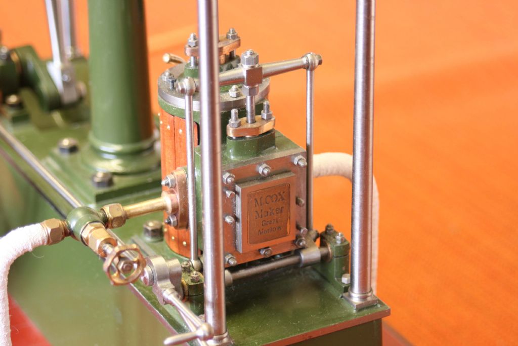
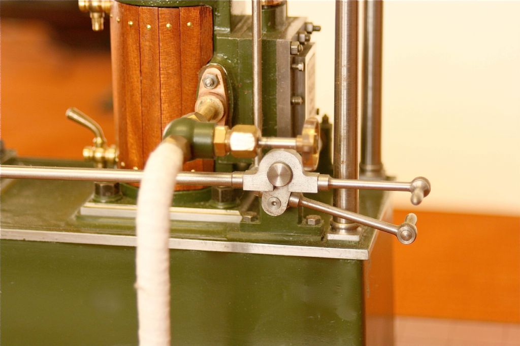
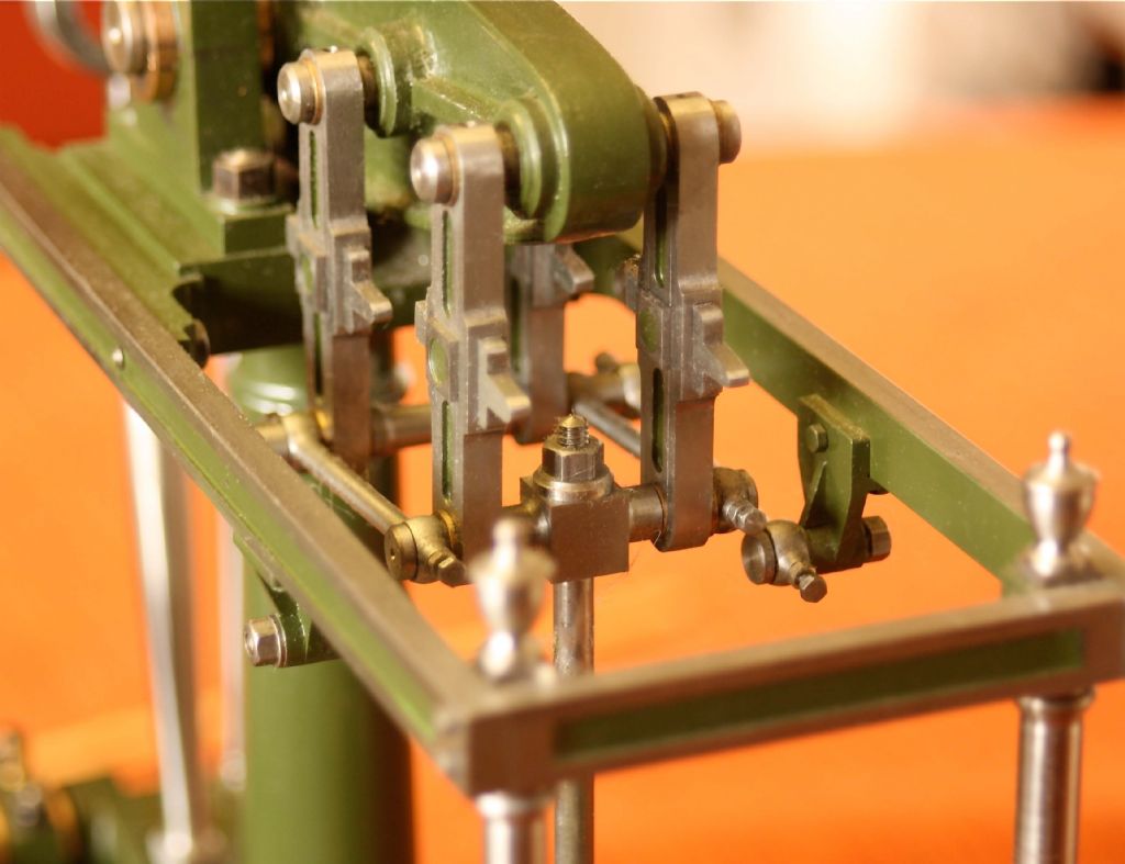
I thought that the modifications that I made to a Stuart beam engine a few years ago might be of interest. The original entablature consists of two steel bars secured at one end to the centre column, and at the other to fresh air. I changed this to the arrangement shown in the pictures; a column at each corner to secure a frame, finished off with finials.
I added starting gear to the valve operating shaft, which is carried in plumber blocks, instead of the triangular brackets supplied by Stuarts. They employ the same casting to carry the ends of the radius arms; I have substituted the fabricated brackets shown in the pictures. The parallel motion is based on full size practice. However, the brasses are not in fact split, but pressed in, in two pieces, into the straps, or "loops". The ends of the pins in the beam are separate, like threaded drawing pins, so that the main loops can be slipped onto the pins without having to be split.
The beam itself has had a central rib added, and the bosses enlarged. Forcing screws have been added to the cylinder top, and steam chest covers. I added a 1/8" square steel lip around the top edge of the bed, so that it seems to owe less to jelly mould technology. The width and length of the added lip is the same as the upper frame, which makes it easy to stand the engine on end on a flat surface to enable measurements to be taken when aligning the beam trunnion bearings.
Having made these changes, it now of course needs a (dummy) air pump between the cylinder and the column, a feed pump between the column and crankshaft, and of course a nice Watt governor on a bracket straddling the crankshaft! I do actually have a pair of bevel gears that would be ideal. All I need is the time!
Maurice
(Sorry that the pics are either side of the text; don't know why that happens). ((Moved by moderator))


Edited By JasonB on 10/01/2016 07:31:44
 JasonB.


