Model Turbines
Model Turbines
Home › Forums › Stationary engines › Model Turbines
- This topic has 606 replies, 28 voices, and was last updated 12 July 2025 at 16:28 by
Turbine Guy.
-
AuthorPosts
-
10 September 2020 at 18:28 #495130
SillyOldDuffer
Moderator@sillyolddufferPosted by Turbine Guy on 10/09/2020 17:00:04:Posted by Werner Jeggli on 18/06/2019 16:59:16:The torque of the turbine determines the speed it can spin the propeller. What makes this even worse, is the very small number of propellers available with test data showing their performance at low powers and high speeds. Because of this and his distrust of extrapolating results, Werner has described my method of testing as “woefully inadequate”. I believe that if you are primarily interested in finding the maximum performance at a particulate speed or range of speeds, you do need a much more sophisticated test method. Either Werner’s method or the use of a torsion type of dynamometer would substantially improve the testing. I do believe that using the performance of a propeller given at a speed within a tested speed range is valid and if it meets your needs, is far simpler and less costly.
…
Don't rush to beat yourself up. The propeller method has several advantages provided it's used within a suitable speed range and a decent calibration curve is available. Cheap and easy. But it can't be safely extrapolated over too wide a speed range, and they become ever more inaccurate as RPM falls.
A torsion dynamometer has a long springy shaft highly likely to whip at high speeds. They're best suited to low rpm engines. I don't think I'd risk putting one on a turbine, something else is needed.
Werner's approach is my favourite of the three but it too has disadvantages. Biggest issue perhaps is the dynamo introduces a second layer of uncertainties. It applies a load between the turbine output and the dynamo's output, notably the bearings, so power is lost before it gets to the rotor. Then the mechanical to electrical conversion efficiency of the dynamo has to be found over a range of speeds if accuracy is very important. And care has to be taken measuring volts and amps. Nothing awful but it all needs attention. Once calibrated Werner's setup is straightforward to use but it's the most expensive solution to build – far more elaborate than a simple propeller, and less accurate than a Brake Dynamometer in that it doesn't measure power directly. Still a jolly good thing though: worth building one to progress your interest in turbines I think.
Boils down to horses for courses again. Like many technologies the propeller gives useful power indication up to a point; the fun bit is recognising when results are suspect and a different approach is needed. The history of science is littered with examples of clever chaps gradually improving step by step; took about 250 years for experimental technique to improve enough to measure the mechanical equivalent of heat consistently to high accuracy.
Keep up the good work.
Dave
10 September 2020 at 20:26 #495156Turbine Guy
Participant@turbineguyThanks Dave,
As I've previously stated, the propellers meet most of my needs. I threw in Werner's method because I feel it has a lot of merit and is probably the way I would go if I needed to find the power at specific speeds or a range of speeds. As you mentioned, any of the methods have their limitations and vary considerably in their complication and cost.
Stay well,
Byron
10 September 2020 at 21:04 #495160Mike Tilby
Participant@miketilby23489Byron, did I send you a copy of the article by Jim Bamford describing his syrup-tin dynamometer? If not I’ll do so. His device, made in the 1950’s, was a very simple water-brake dynamometer. It had a simple paddle that rotated in water inside the syrup-tin. The tin was pivoted and had an arm attached on which weights could be attached and adjusted in distance from the axis until the arm was balanced horizontal when the turbine was stationary. The shaft from his turbine entered the tin through the centre of one of the pivots and as the paddle turned it tended to rotate the tin. The load on the turbine was adjusted by bending the blades of the paddle (or the water level). Prof. Dennis Chaddock, who had used spinning bars equivalent to your propellers, later wrote that Jim Bamford’s syrup-tin dyno was a brilliant innovation.
Too many years ago I made one of these syrup-tin dynos and played around with it. Now I’m older and greyer I thought I’d make a proper one with discs as invented by Froude. That is part built. My initial intention was to use one of the cheap electronic scales one can buy to measure force on the arm instead of weights, but it would be much better to record torque continuously rather than writing down the reading from time to time while also controlling a boiler etc. Recently, a friend who is an electronics expert, built a dyno with a motor/generator to provide an adjustable load. In his device the motor is only the load and torque on the motor is measured directly with a load cell. I understand that analysing the signal from a load cell requires a very high gain accurate amplifier and,based on past experience, I foresee problems with interference etc. So combining a torsion bar with a water brake has some attraction for me. However, at current rate of progress the time when I’ll need the dyno is a long way off.
Regards, Mike
11 September 2020 at 00:12 #495186Turbine Guy
Participant@turbineguyPosted by Mike Tilby on 10/09/2020 21:04:06:Byron, did I send you a copy of the article by Jim Bamford describing his syrup-tin dynamometer? If not I’ll do so. His device, made in the 1950’s, was a very simple water-brake dynamometer. It had a simple paddle that rotated in water inside the syrup-tin. The tin was pivoted and had an arm attached on which weights could be attached and adjusted in distance from the axis until the arm was balanced horizontal when the turbine was stationary. The shaft from his turbine entered the tin through the centre of one of the pivots and as the paddle turned it tended to rotate the tin. The load on the turbine was adjusted by bending the blades of the paddle (or the water level). Prof. Dennis Chaddock, who had used spinning bars equivalent to your propellers, later wrote that Jim Bamford’s syrup-tin dyno was a brilliant innovation.
Too many years ago I made one of these syrup-tin dynos and played around with it. Now I’m older and greyer I thought I’d make a proper one with discs as invented by Froude. That is part built. My initial intention was to use one of the cheap electronic scales one can buy to measure force on the arm instead of weights, but it would be much better to record torque continuously rather than writing down the reading from time to time while also controlling a boiler etc. Recently, a friend who is an electronics expert, built a dyno with a motor/generator to provide an adjustable load. In his device the motor is only the load and torque on the motor is measured directly with a load cell. I understand that analysing the signal from a load cell requires a very high gain accurate amplifier and,based on past experience, I foresee problems with interference etc. So combining a torsion bar with a water brake has some attraction for me. However, at current rate of progress the time when I’ll need the dyno is a long way off.
Regards, Mike
Hi Mike,
You sent me both Jim Bamford's and Prof. Chaddock's articles. I have read them several times and gained a lot from both of them. Thanks again for sending these.
I'm not at a stage yet that I feel I need a more elaborate method for doing my turbine testing. Prof. Chaddock felt the data he had on his bars was adequate enough to use them. I feel the data for the propellers I use is at least as good. I agree with everyone that for low speeds the extra complexity might be needed.
Stay Well,
Byron
17 September 2020 at 15:17 #496333Turbine Guy
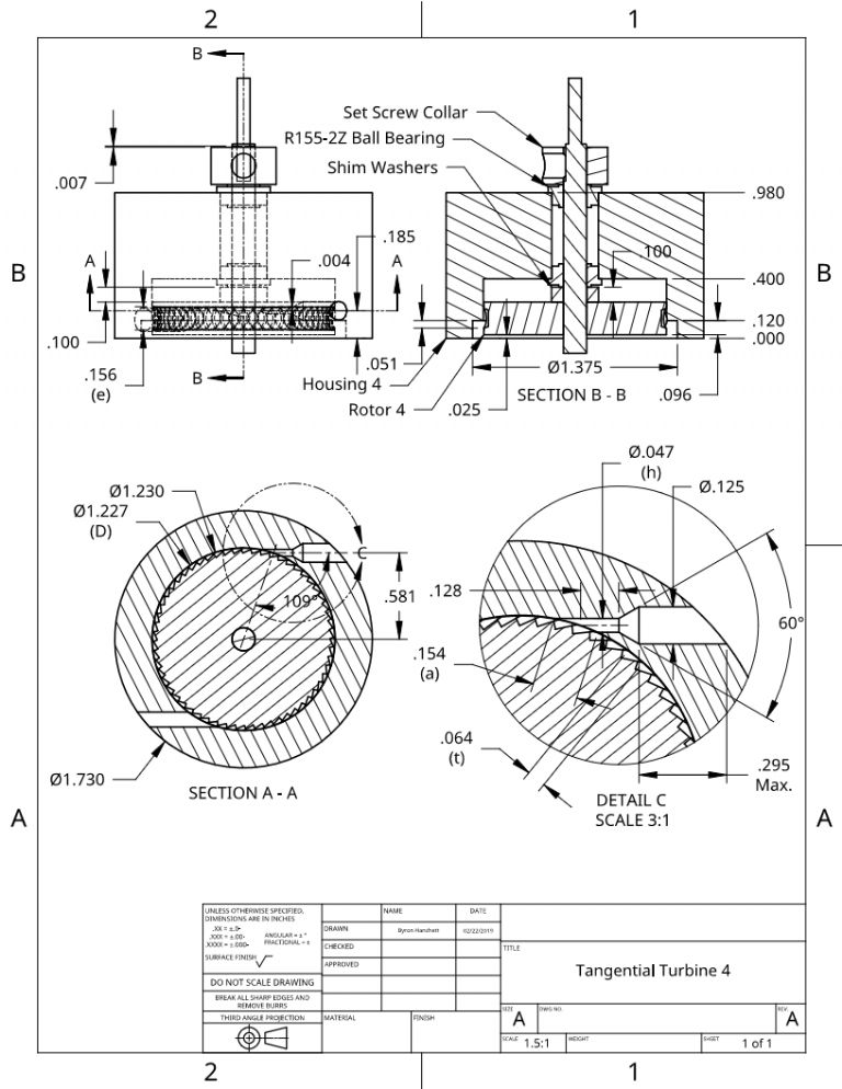
Participant@turbineguyI have a few more things I would like to try with the tangential turbine. The following drawing shows a preliminary design of a new turbine that hopefully will allow me to test the merit of these concepts. The first thing I will try is to run at less than sonic velocity. My calculations indicate that there is a potential for higher performance running at below sonic velocity for the convergent only nozzles. My tests and Werner Jeggli’s tests have shown that there needs to be a free space for the gas exiting a sonic nozzle to expand to supersonic velocity before contacting the rotor. I discuss this in the post of 31/01/2020 in this thread. I can’t provide the free space with the open pockets, since a close clearance between the rotor OD and housing ID is needed to keep the gas from flowing over the rotor. I wasn’t able to make the flow subsonic by using multiple nozzles in my Turbine 3. I tried several times to add a nozzle and each time the tiny drill drifted far enough that the nozzle was useless. I decided I would try a larger nozzle and try getting the starter drill with the 60 degree taper closer to the inside diameter of the housing. You can see from the drawing below that the length of the nozzle diameter is very short with this design. The increased nozzle diameter and short length will help keep the nozzle from drifting and decrease the pressure drop in the nozzle. I will discuss the other things I want to try in later posts.
17 September 2020 at 16:17 #496344Turbine Guy
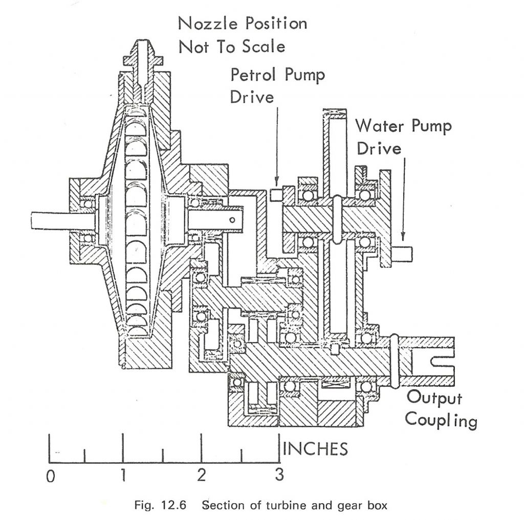
Participant@turbineguyTo try different concepts in the same turbine, I needed to make some compromises. Some of these compromises are shown in the drawing of the previous post. The second thing I wanted to try was having the flow exit from the rotor face rather than from the OD into a countersunk opening. The flow exiting into a countersunk opening is what I have used so far for all the tangential turbines I have made. The flow exiting the face of the rotor is what Jim Bamford used in his tangential turbine as shown in the drawing below copied from Experimental Flash Steam by J.H. Benson and A.A Rayman. For flow exiting the face of the rotor, the counterbore is not needed and simplifies the turbine. I designed a turbine for a friend using this concept but have not tried it yet. The compromise I made in Turbine 4 to test this concept was so that I could also test with the counterbore. I want to see which of these methods is the most efficient with the overlapping pockets. The rotor shown in the drawing of the last post shows the setup for running with the counterbore. I need to test this first since the flange on the outer face of the rotor will need to be machined off to allow the flow to exit from the face. When I complete all the testing with the counter bore, I will machine the outer face of the rotor and reduce the length of the shims to where the OD of the rotor is entirely under the ID of the housing. This is why I used such a long shim length and pushed the rotor so far out. A second nozzle, not shown in the drawing of the previous post, will also be needed since the rotor is in a different position. This nozzle will be exactly the same except for its position that will be moved in the same amount as the rotor moves in.
Edited By Turbine Guy on 17/09/2020 16:27:35
20 September 2020 at 07:37 #496829 Blue HeelerParticipant@blueheeler
Very interesting thread.
27 September 2020 at 12:34 #498126Turbine Guy
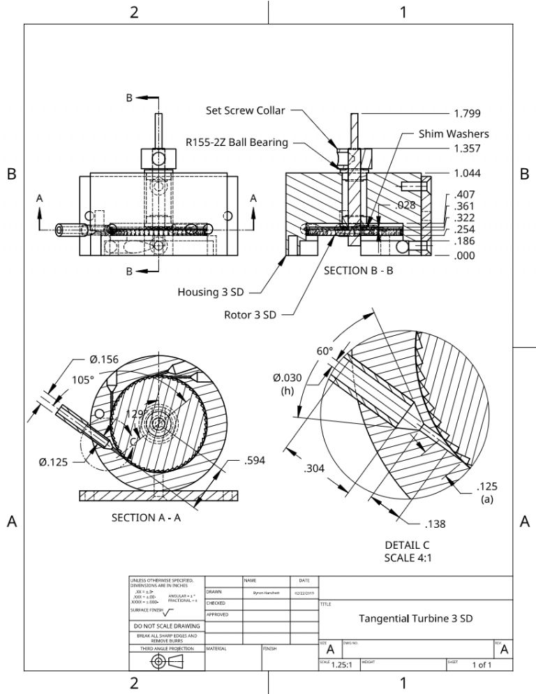
Participant@turbineguyAfter posting the drawing of Jim Bamford’s turbine shown in my last post, I thought I would try adding a new nozzle to Turbine 3. I ruined the existing nozzle when I tried putting an insert into it. I thought when I added the insert, that if it didn’t work, I could push it out. I tried to add a new nozzle several times, but each time the tiny nozzle drill drifted too far to be useable. Thor suggested that I run the nozzle drill at a much higher speed than I had been using. All my drill speed charts also recommended the higher speeds. I tried drilling the nozzle shown in the following drawing using the maximum speed of my milling attachment (4,000 rpm). I was able to drill the hole without the drill wandering or breaking. I didn’t realize the importance of using the right drill speed. The new nozzle is positioned where the rotor OD is overlapped by the housing so I can try having the flow exit from the rotor face instead of into a counterbore. The drawing also shows how one row of the rotor pockets will be removed. This will make a better comparison of the two methods since it will be with the same rotor, same nozzle size, and same nozzle angle. This will also allow me to use rotor 3 again since I can only run the axial rotor now.
27 September 2020 at 12:35 #498128Turbine Guy
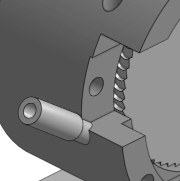
Participant@turbineguyThe view of my 3D solid model showing the area near the new nozzle might make it easier to see how the flow enters and exits the rotor. The opening in the housing next to the new nozzle was used to mount the reversing chamber. The face of this opening is approximately where the center line of the new nozzle is. The center of the flow exiting the nozzle enters the rotor where this surface lines up with the rotor. The flow exits the rotor through the openings on the rotor face. The more of the face of the rotor that is machined off the larger the openings become but the amount the flow is turned is reduced. There will be an optimum value of the amount of material removed from the rotor. I will try to find the optimum amount by removing a little at a time and then testing.
29 September 2020 at 17:19 #498498Turbine Guy
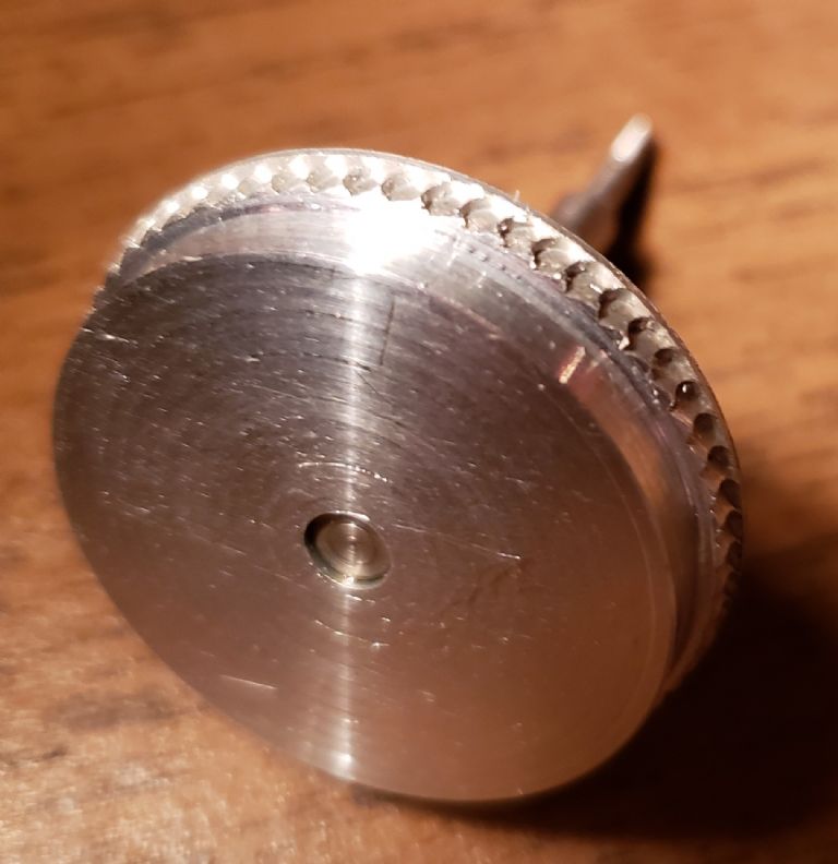
Participant@turbineguyI machined the face of Rotor 3 removing one row of pockets and opening the remaining row of pockets for side discharge. Machining the pockets off resulted in breaking the Loctite bonding the shaft to the rotor. I had to make a fixture clamping the rotor to the shaft with nuts to finish the machining. I then glued the rotor to the original shaft with Loctite 290 as I have done for all my other rotors. The following picture shows the finished rotor. I’ll start the testing tomorrow after the Loctite reaches it’s full strength. Because the Loctite didn’t withstand the force of machining the pockets, I won’t try removing the metal a little at a time as I previously planned to do. If the initial testing indicates this is necessary, I will key the rotor to shaft before I try any machining.
30 September 2020 at 19:22 #498709Turbine Guy
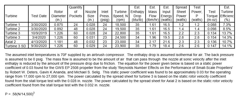
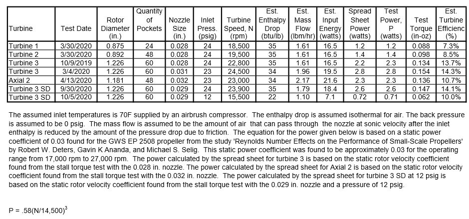
Participant@turbineguyI updated the following test results to include running Tangential Turbine 3 with the side discharge (SD) rotor on air. I found the optimum position of the rotor was with 7 shims and setting the collar clearance to 0.004 in. The maximum speed obtained with the SD rotor had similar performance to that of the original rotor. There didn’t appear to be any disadvantages eliminating the counterbore required by the original rotor. This eliminates one machining operation on an already simple turbine. This was probably why Jim Bamford used this method on his turbine. I was concerned that the clearance around the rotor OD added by overlapping the pockets would be a problem. Apparently, the momentum of the air keeps it pushed against the turning surface of the rotor pocket. The loss in performance due to not turning the flow 180 degrees appears to be offset by less surfaces in the path of the air discharging from the rotor. The rotational (windage) loss improvement by removing one row of pockets makes a direct comparison of the two methods slightly unfair.
10 October 2020 at 13:10 #500527Turbine Guy
Participant@turbineguySince I was able to test the performance of my Turbine 3 with a side discharge (SD) rotor, the effect of running at a lower pressure was the next thing I wanted to check. I ran a test of Turbine 3 SD with the 0.029” diameter nozzle on 12 psig with my EP2508 propeller. The power obtained was considerably less than estimated with my spreadsheet with the rotor velocity coefficient (RVC) I have been using. I could not find any reason for the performance being less than estimated other than the RVC. I ran a stall torque test and found the RVC at 12 psig the same way I have shown several times and it’s value was only 0.059. When I used this value of the RVC in my spreadsheet, the power estimated was very close to the test result. I updated the following turbine test sheet to show the results of these tests.
 24 November 2020 at 12:48 #509582
Turbine Guy
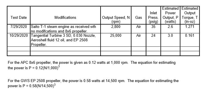
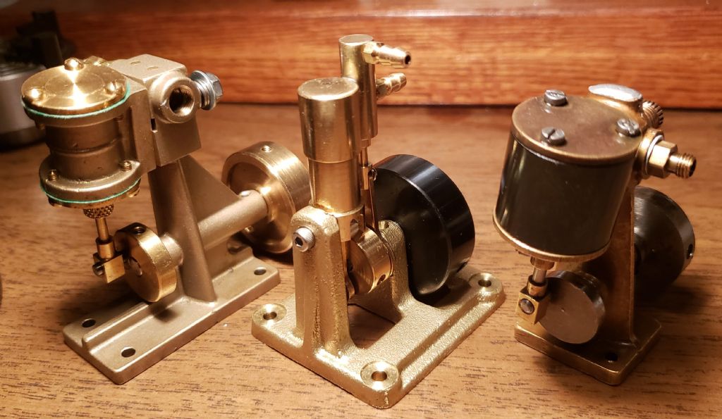
Participant@turbineguyMy goal when I started this thread was to come up with a turbine design that could be made by modelers with small lathes and require no more equipment than is necessary to make a small steam engine. My goal was also to come up with a turbine design that matched the performance of the available model steam engines. I purchased three model steam engines shown in the photo and ran tests of them in the Testing Models thread The following table shows the comparison of the last tests with my Turbine 3 SD and the Saito T-1 that had the best performance of the three purchased steam engines. Turbine 3 SD met all my goals, at least, for running on air with my airbrush compressor. The Testing Models link shows the updates to the drawings of Turbine 3 SD to show the last changes made to the rotor and assembly. The updated drawings show all the changes including those to correct mistakes or needed for other concepts no longer used. I will make new drawings showing the turbine design cleaned up and representing what worked the best from all my testing.
Edited By Turbine Guy on 24/11/2020 12:54:39
26 November 2020 at 12:28 #509985Turbine Guy
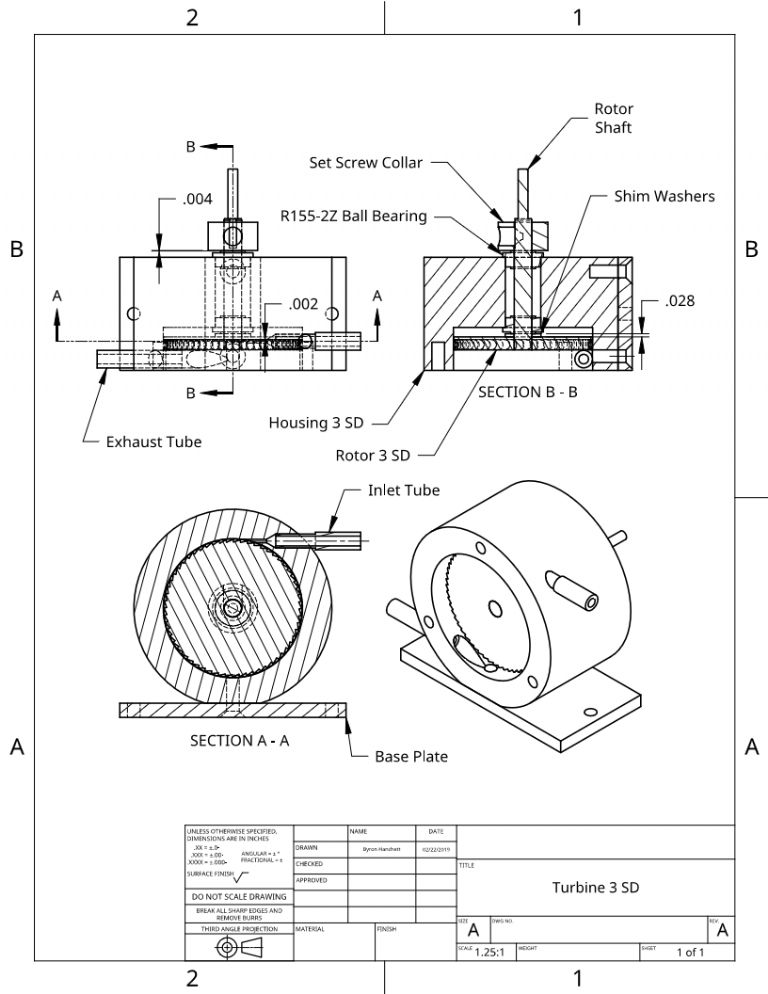
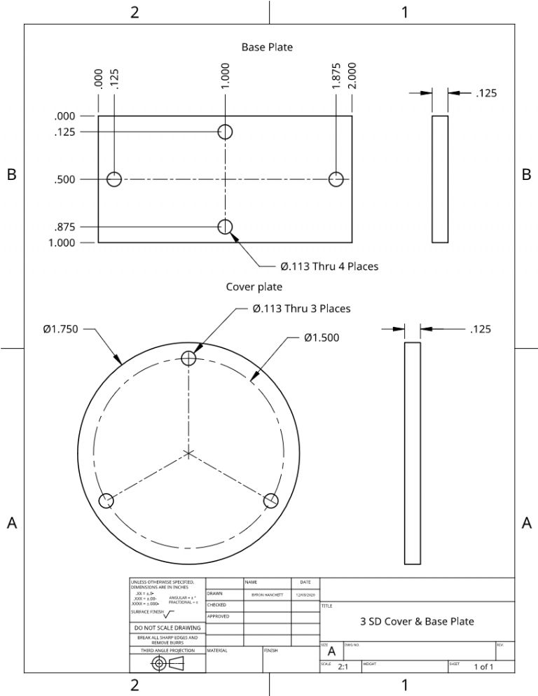
Participant@turbineguyThe following drawing is the cleaned up version of Turbine 3 SD. This turbine can be made with most materials, parts, and tools purchased from one source as will be shown in the next post. To make it the way I have, requires a mill or milling attachment and an indexer. I used the milling attachment and indexer available for my Unimat 3. All the Unimat accessories have threads that allow mounting of all the chucks so a part mounted in a chuck can be mounted on the lathe, mill, or indexer without removing it from the chuck. I was able to do all the critical machining of the parts without removing them from the chucks.
26 November 2020 at 12:38 #509986Turbine Guy
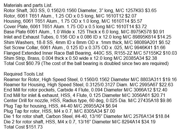
Participant@turbineguyMost of the materials, parts, and tools needed to make Turbine 3 SD can be purchased from McMaster-Carr. The following shows McMaster-Carr part number and cost of each item. You can open McMaster-Carr using the link and type in the part number to get a picture and full description.
27 November 2020 at 15:59 #510232Turbine Guy
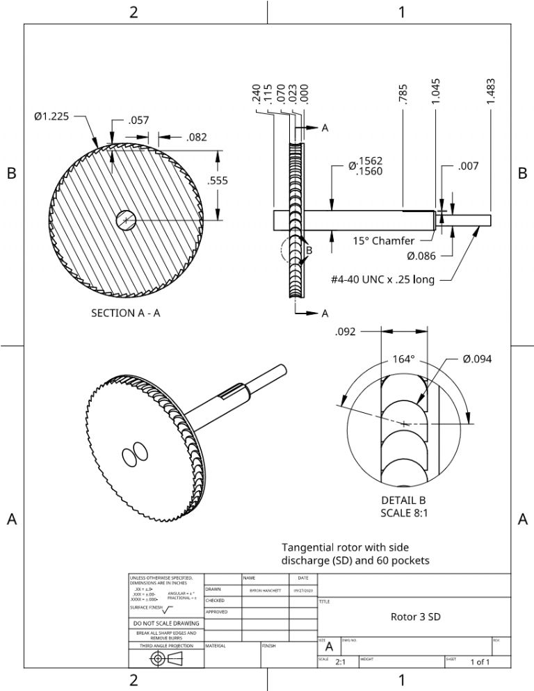
Participant@turbineguyThe following drawing shows the Turbine 3 SD rotor. I’ve made rotors out of brass and silver soldered them to the stainless steel shafts and made them out of aluminum and used a light press fit with Loctite 290. I prefer the aluminum since it is less expensive and reduces the rotating mass. I extended the shaft on both sides of the rotor to use Werner Jeggli’s method of balancing the rotors. I will explain his method in another post. I thought of adding the shaft extension after making the assembly drawing, so it doesn’t show up on it. I don’t have anything for measuring except a dial caliper with +/- 0.001 accuracy so I use precision ground shafting for the rotor shaft. I will show the setup I use for making the rotor pockets and explain the steps I use in the next post.
27 November 2020 at 19:34 #510287Turbine Guy
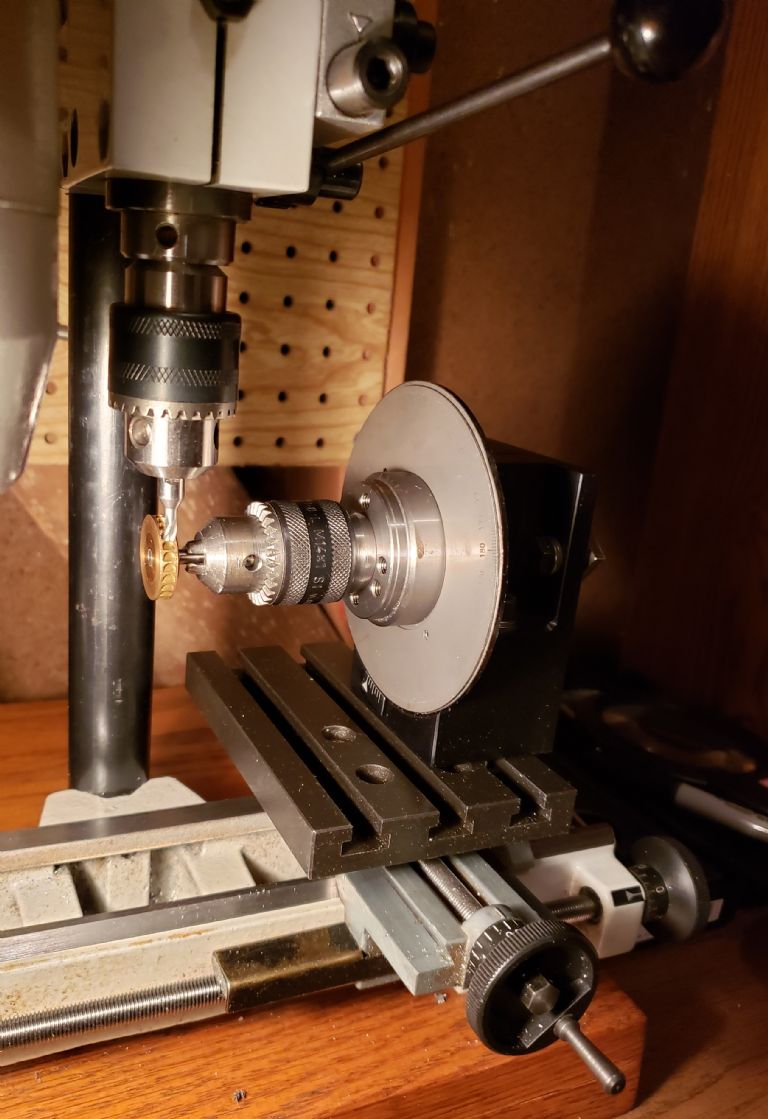
Participant@turbineguyAfter the rotor is machined to where the OD and thickness are slightly oversize, the bore for the rotor shaft is drilled and reamed. Next the rotor bore has a thin coating of Loctite 290 added and then the rotor pressed into position. The initial grip of Loctite 290 is relatively quick so the rotor needs to be in it’s correct position and the excess Loctite wiped off as soon as you can. The Loctite will also glue your chuck jaws to the rotor shaft if you allow it to flow onto the jaws. I allow 24 hours for curing time to get the full strength of the Loctite before facing both sides of the rotor and machining the OD to their final dimensions. The next step is machining the pockets. The photo below shows the setup I use to make the pockets. I used my rotor 1 in this photo since the larger pockets and the brass shows the pockets clearer. I will describe how I position the end mill and machine the pockets in the next post.
28 November 2020 at 20:10 #510508Turbine Guy
Participant@turbineguyWhen setting up the indexer as shown in the picture of the last post, it is very important that the face of the rotor is parallel with the direction of movement of the cross slide. This will keep the sides of the pockets parallel to the rotor faces. After I have the indexer carefully squared up and bolted firmly to the mounting plate, I adjust the rough position of the end mill. I set up the end mill to a position that when it is fully retracted, it’s end will be slightly above the rotor. I then lock the milling attachment in position and make all the changes of rotor position with the carriage using the cross slide and long slide. I set the position of the long slide first. I move it to position that the end mill is on the left side of the rotor and then extend it down far enough that it will overlap the face of the rotor for most of it’s cutting length.. I then move the long slide until the end mill contacts the rotor face and read the scale on the long feed handwheel. Next, I raise the end mill enough to clear the top of the rotor. Then I move the long slide to the left using the scale on the handwheel to move the correct distance. The distance of this move for the turbine shown in the preceding drawing is 0.092”. I then lock the carriage in that position. The next thing to do is position the end mill to where its center is close to the center of the rotor. Using the fine feed of the mill chuck, I then lower the end mill until it contacts the top of the rotor and note the reading on the scale of the fine feed. Next the rotor is moved by the cross slide far enough that the end mill can be lowered without contacting the rotor. Then using the mill chuck fine feed, the end mill is lowered to the correct distance from the top of the rotor. The distance of this move for the turbine shown in the preceding drawing is 0.057”. The mill chuck fine feed is then locked in that position. Note that the most important distance is from the center of the rotor to the bottom of the end mill (0.555). If the actual rotor OD is correct, then the 0.057 distance can be used. If not, the correct distance should be determined by subtracting the 0.555 from the actual radius of the rotor. The last thing for this setup is determining the end of travel for the cross slide. Move the cross slide until the end mill first contacts the rotor. Note the position on the cross slide handwheel and then start the motor and make the first cut the correct distance. The distance of this move for the turbine shown in the preceding drawing is 0.082”. Note the handwheel position at the end of travel. If you can’t set up a stop for the cross slide, the cross slide will have to be moved out far enough to clear the rotor and then moved back to this position for each movement of the indexer. If you can set up a stop, you still need to move the cross slide in and out, but you don’t have to keep track of the number of turns of the handwheel. These are the steps I’ve used to make three rotors using my equipment and lack of measuring devices. Hopefully, some of this discussion will be helpful.
29 November 2020 at 18:10 #510673Turbine Guy
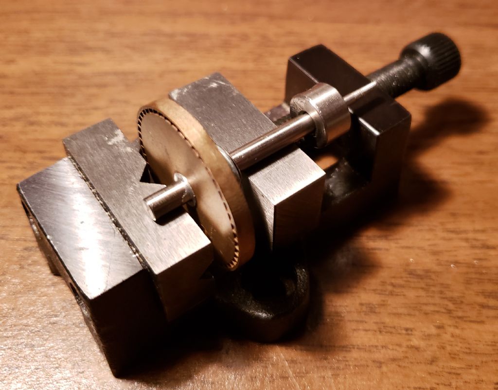
Participant@turbineguyAfter all the machining of the rotor is finished, it needs to be balanced. This is especially important if it is operated at high speeds. Werner Jeggli has the best method I have seen for doing this. He extends the shaft through the rotor so that the diameter is the same on both sides of the rotor. The rotor can then be placed on two flat horizontal surfaces like in the following picture. I was amazed how low the imbalance had to be to cause the rotor to roll to a position that the out of balance weight ended up at the bottom. I only found out this method after I got one of Werner’s cast rotors. I made the shaft his way and used his method for balancing it. That is rotor I show in the picture and has the best balance of any of my rotors. I attach the shaft collar when I do the balancing since it is a set screw collar that will have a small amount of imbalance due to the set screw and the flat made on the rotor shaft. It is a great method that can be used for a lot of rotating parts.
1 December 2020 at 16:50 #511075Turbine Guy
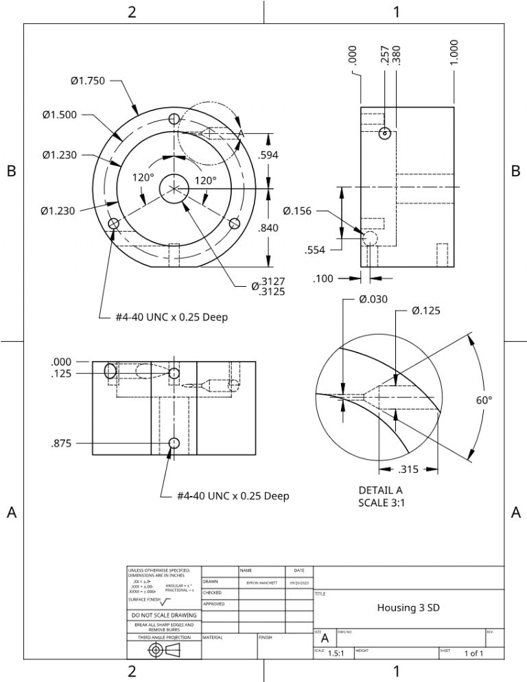
Participant@turbineguyThe following drawing shows the Turbine 3 SD housing. It was designed to allow all the critical machining to be done without removing the housing from the chuck. I start the machining by mounting the bar in my 3 jaw chuck and facing one end. I then put the cleaned up end against the face of the 3 jaw chuck and tighten the chuck firmly. Next I machine the outer face and then do the counter bore to the correct depth but with a smaller than finished size diameter. I then gradually increase the counter bore diameter until the rotor will just slide in. The next step is to drill and ream the through hole that holds the ball bearings. Then the portion of the OD of the bar that extends beyond chuck jaws is machined just enough to clean it up. This portion will be used for measurements.
1 December 2020 at 18:51 #511101Turbine Guy
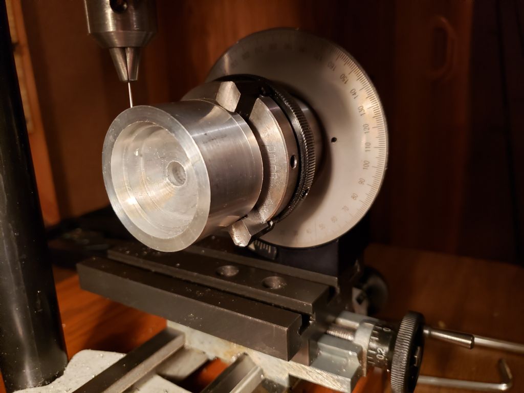
Participant@turbineguyAfter finishing the machining described in the last post, I remove the chuck from the lathe and mount it on the indexer as shown in the photo below. This is the setup for drilling the nozzle hole. What is not shown in the photo, is the threaded rod with washers and nuts that I run through the chuck and indexer center holes. I do this to hold the housing tightly against the chuck face. I position the indexer by moving the carriage long feed and cross feeds to the correct position similarly to the way I located the end mill for making the pockets in the rotor. After the carriage long feed and cross feed are locked in position, I make sure that I have enough space for changing from the end mill, to the center drill, and then to the nozzle drill. I then move the end mill down until it contacts the housing and using the fine feed scale, machine to the required depth. This depth is the 0.315 dimension shown in the drawing of the last post. I measure the distance from the point of my center drill to the start of the taper. This is the distance the center drill will need to move from first contact. I then change the mill to the center drill and machine it to the correct depth using the fine feed. The final operation is drilling the nozzle hole. I found it is very important to run the small nozzle drill at the mills highest speed and only extend it from the chuck the minimum possible. I will show in the next post a type of drill that, if available, really helps. After the nozzle hole is finished and housing is still in its original position in the 3 jaw chuck, the chuck and or indexer can be moved as needed to add the cover plate mounting holes.
1 December 2020 at 19:43 #511108Turbine Guy
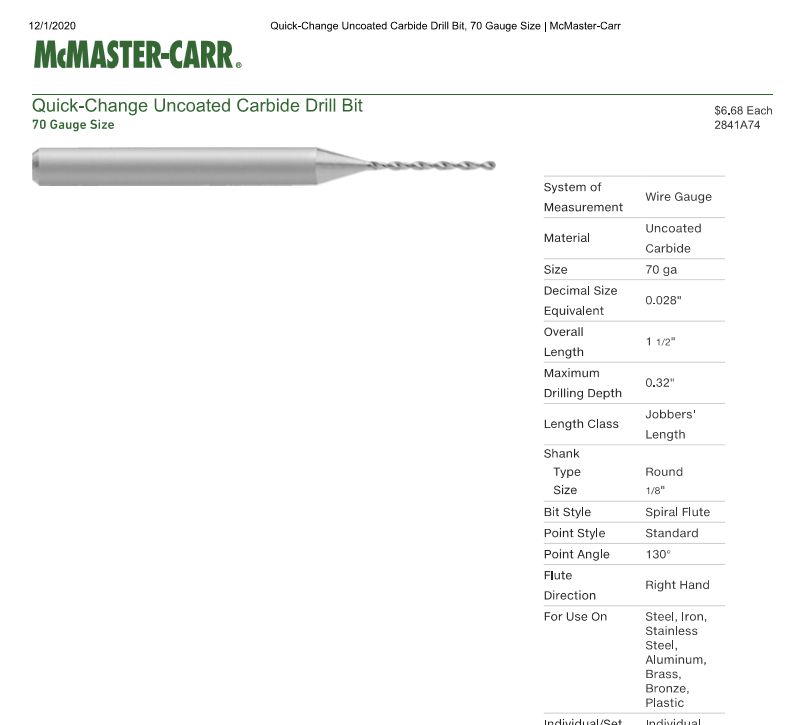
Participant@turbineguyThe drill I mentioned in the last post is called a quick-change drill. An example is shown below. This type of drill gets it’s name from having the same larger diameter so that one collet can be used for many small drills. What is helpful for drilling nozzles, is the relatively short cantilever length of the drill. Since I use a 0.125 diameter end mill for the inlet hole, the large diameter portion can extend into the milled hole and give the drill additional support. I tried one of these on the last nozzle I drilled and it seemed to work well.
3 December 2020 at 15:20 #511416Turbine Guy
Participant@turbineguy9 December 2020 at 17:05 #512575Turbine Guy
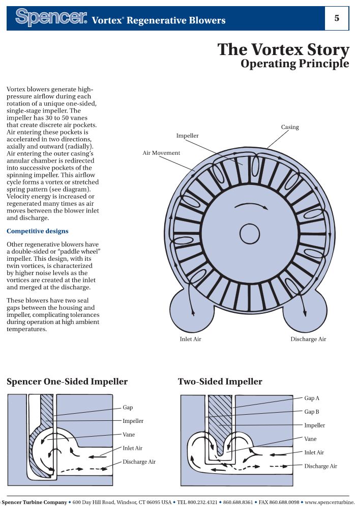
Participant@turbineguyI have tried everything I planned to do with the tangential flow impulse turbines so I am going to try designing what Dr. Balje called a drag turbine. His document ‘A Study of High Energy Level, Low Power Output Turbines’ done for the Office of Naval Research in 1957 gives guidelines for designing drag turbines. His guidelines for designing Terry Turbines in this document, were what I used designing my tangential flow impulse turbines. The drag turbine operates on the same principle as a regenerative blower or turbine pump. The following page from the Spencer Vortex Regenerative Blower catalog explains this principle and shows a one-sided version and a two-sided version. I prefer the one-sided version for the reasons they give plus it will be so much easier to make.
9 December 2020 at 18:23 #512597Turbine Guy
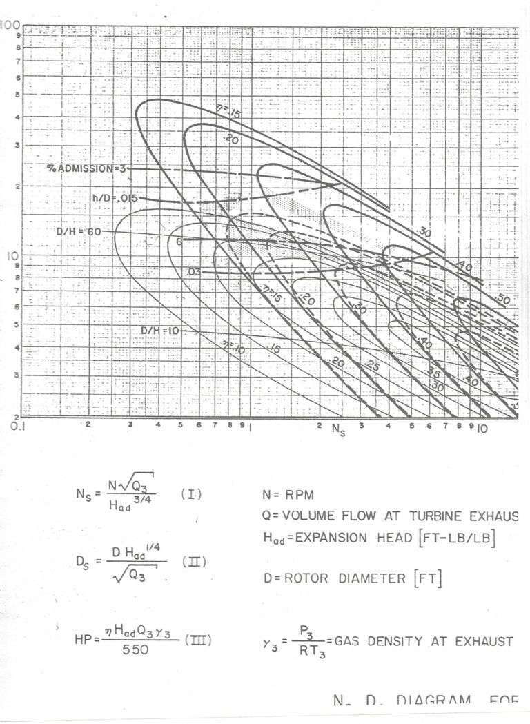
Participant@turbineguyThe chart shown below and in some earlier posts is copied from ‘A Study Of High Energy Level, Low Output Turbines’ prepared by Dr. O. E. Balje for the Department of the Navy in December 1957. This chart illustrates the maximum performance he estimated for various types of turbines when optimized. The heavy solid lines in the chart are for axial turbines. The dashed lines are for Terry turbines. The thin solid lines are for Drag turbines. The units for the volume flow are ft3/sec and lb/ft3 for the gas density. Dr. Balje intended this chart be used by determining the volume flow at the turbine exhaust (Q3) and expansion head (Had) of the supply gas. My airbrush compressor can supply a volume flow of 0.011 ft3/sec at a pressure of 10 psig (25 psia). The expansion head for air at a pressure of 25 psia is 14,800 ft-lb/lb. Once the expansion head and exhaust volume flow are found, you choose the rotor OD and speed you would like to run and calculate Ns and Ds. I decided to try a rotor OD of 0.927” and a speed of 25,000 rpm for Drag Turbine 1. With this rotor diameter and speed, Ns = 2 and Ds = 8.1. From the chart, the maximum efficiency of an optimized drag turbine is estimated to be approximately 30%.
-
AuthorPosts
- Please log in to reply to this topic. Registering is free and easy using the links on the menu at the top of this page.
Latest Replies
Home › Forums › Stationary engines › Topics
-
- Topic
- Voices
- Posts
- Last Post
-
-
Polishing compounds for stainless steel (mild abrasives))
Started by:
Simon Williams 3 in: Beginners questions
- 13
- 14
-
20 July 2025 at 20:02
 Russell Eberhardt
-
Hofmann Rollers
Started by:
Martin Kyte in: General Questions
- 2
- 2
-
20 July 2025 at 19:53
 Julie Ann
-
Bad design, or am I missing something?
Started by:
half whit in: Beginners questions
- 5
- 7
-
20 July 2025 at 19:16
 Julie Ann
-
Mistry dividing attachment
1
2
Started by:
Brian Merrifield in: Workshop Tools and Tooling
- 17
- 42
-
20 July 2025 at 18:43
 Tony Jeffree
-
Hopeless…Alibre Ass
Started by:
Nigel Graham 2 in: CAD – Technical drawing & design
- 4
- 10
-
20 July 2025 at 17:48
Diogenes
-
Lidl castors
Started by:
 Michael Gilligan
in: The Tea Room
- 3
- 3
-
20 July 2025 at 17:43
 Bazyle
-
Epoxy or acid etch primer
Started by:
Michael Callaghan in: Materials
- 1
- 1
-
20 July 2025 at 16:46
Michael Callaghan
-
Diving in to ATC?
Started by:
Steve355 in: CNC machines, Home builds, Conversions, ELS, automation, software, etc tools
- 4
- 6
-
20 July 2025 at 16:20
 Martin Connelly
-
What Did You Do Today 2025
1
2
…
8
9
Started by:
 JasonB
in: The Tea Room
- 33
- 201
-
20 July 2025 at 16:13
 JasonB
-
Measuring a double Vee lathe bed Vee position
Started by:
Kim Garnett in: General Questions
- 11
- 22
-
20 July 2025 at 15:51
Kim Garnett
-
Please direct me to where I can find an engineer to do some bespoke work
Started by:
srb1 in: Beginners questions
- 6
- 10
-
20 July 2025 at 15:43
Craig Brown
-
Making Unimat DB/SL Steadies
Started by:
Andy Carlson in: Workshop Techniques
- 3
- 4
-
20 July 2025 at 15:35
Andy Carlson
-
Alternative to ARC
Started by:
petro1head in: General Questions
- 4
- 8
-
20 July 2025 at 13:31
 JasonB
-
My vise isn’t at 90 degrees
Started by:
moonman in: Beginners questions
- 13
- 16
-
20 July 2025 at 13:26
Tony Pratt 1
-
Sat nag
1
2
Started by:
duncan webster 1 in: The Tea Room
- 24
- 50
-
20 July 2025 at 13:18
Nigel Graham 2
-
Which lubricator do I need
Started by:
Michael Callaghan in: Locomotives
- 3
- 5
-
20 July 2025 at 12:45
Michael Callaghan
-
Advice to machine stationary engine base plate
Started by:
Greg H in: General Questions
- 5
- 12
-
20 July 2025 at 11:37
Greg H
-
Model Engine running just off a naked flame
Started by:
 Blue Heeler
in: Stationary engines
- 3
- 6
-
20 July 2025 at 11:31
 David George 1
-
Paint stripper does not do what it says on the tin
Started by:
Greensands in: Hints And Tips for model engineers
- 8
- 16
-
20 July 2025 at 11:11
 Taf_Pembs
-
Easiest/cheapest source of R8 socket
1
2
Started by:
Beardy Mike in: Workshop Tools and Tooling
- 14
- 27
-
20 July 2025 at 11:01
Tony Pratt 1
-
Hofmann
Started by:
Matt Smith in: General Questions
- 2
- 2
-
20 July 2025 at 10:37
Tony Pratt 1
-
Even the Dealer Didn’t Know!
Started by:
Chris Crew in: The Tea Room
- 15
- 20
-
20 July 2025 at 07:54
Nealeb
-
Boxford paint colour
Started by:
 Pete.
in: Workshop Tools and Tooling
- 5
- 10
-
20 July 2025 at 01:21
 Pete.
Pete.
-
More BBC Masterchef woes…
Started by:
 Nigel Bennett
in: The Tea Room
- 6
- 6
-
19 July 2025 at 22:55
Nigel Graham 2
-
Boley 6LZ, new to me
Started by:
Wade Beatty in: Manual machine tools
- 4
- 5
-
19 July 2025 at 22:47
Wade Beatty
-
Polishing compounds for stainless steel (mild abrasives))
-
Latest Issue
Newsletter Sign-up
Latest Replies


