Model Turbines

Advert

Model Turbines

Home Forums Stationary engines Model Turbines

Viewing 25 posts - 151 through 175 (of 562 total)
  • Author
    Posts
  • #459875
    Turbine Guy
    Participant
      @turbineguy

      Hi Werner,

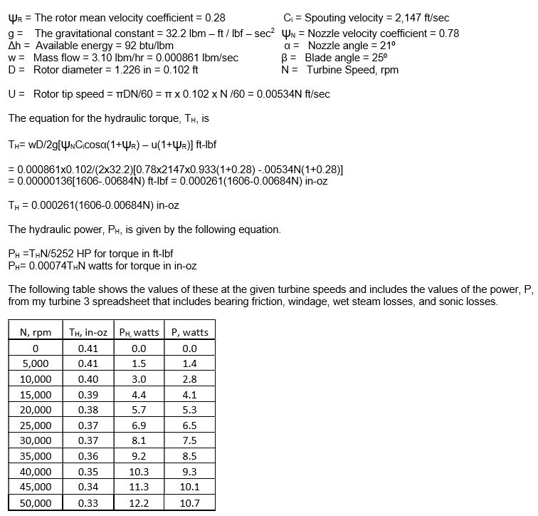
      The output torque drops as the speed increases due to the rapidly rising rotational losses and smaller difference in velocity between the rotor and the nozzle. The table shown in the post of 01/02/2020 shows an example of this. Earlier posts in this thread explain what was involved in estimating the values shown in that table. I have developed spreadsheets to help estimate the performance with different energy levels, different size propellers, different rotors, and different nozzles. I compare what is estimated in these spreadsheets with any test results to check their accuracy. The post of 26/03/2020 is an example of this. With the spreadsheet used for that test, the estimated power at a speed of 30,000 rpm would be 7.5 watts and the torque would be 0.338 in-oz. If I had the ability to adjust the load to a power my turbine was capable of producing at 30,000 rpm, I could check these values. The down side to using propellers, is that the torque required to turn the propeller determines the speed the turbine can reach. The torque I obtained in this test would spin my GWS EP 2508 propeller at above its recommended operating speed and that is why I am using the larger propeller.

      Hope this helps,

      Byron

      Advert
      #460113
      Turbine Guy
      Participant
        @turbineguy

        I made the following table using the equations and values shown for estimating the performance of my turbine 3 running on steam at a pressure of 50 psig, 15% moisture, 3.12 lbm/hr, and with the 0.031 in. nozzle. The table gives the estimated performance at given speeds, and the equations can be used to find the power and torque at other speeds. The table and equations assume that the torque required by the load does not exceed the torque of the turbine at that speed. Earlier posts detail how I determined the nozzle and rotor velocity coefficients.

        Turbine 3 Hyd. Power B

        #463009
        Turbine Guy
        Participant
          @turbineguy

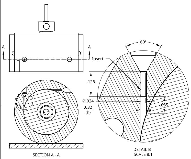
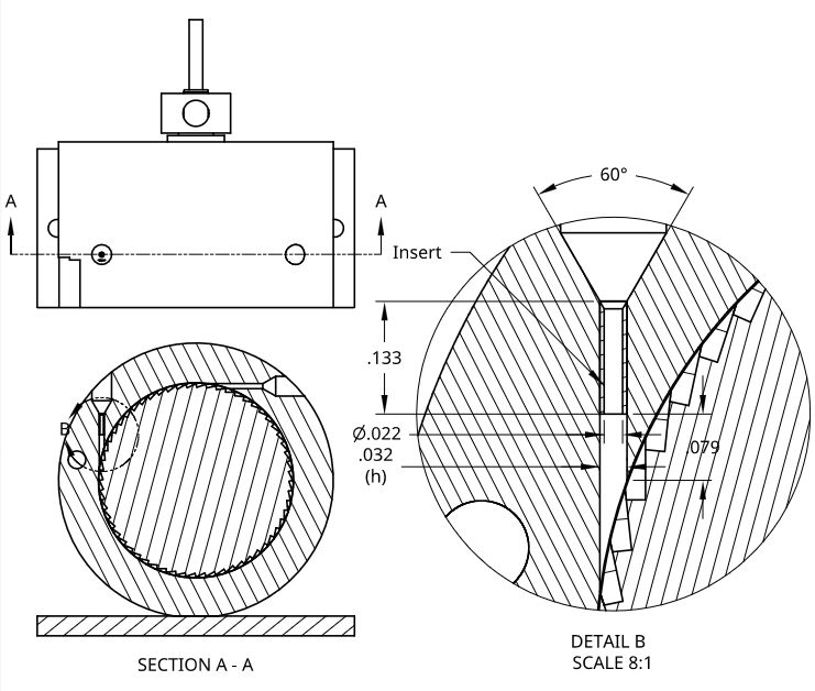
          The following drawing shows a concept I am going to try. This is an attempt to allow the flow exiting from the nozzle to reach its maximum supersonic velocity before contacting the rotor. Detail B is an enlarged view of the section through the nozzle. The 0.032 in. diameter is the existing diameter of the nozzle and is the largest diameter I can fit into the turbine 3 housing. It is also larger than the maximum nozzle size recommended for the rotor pocket size made by the 0.094 in. diameter end mill. The optimum size nozzle for the 0.094 width pocket is 0.029 in. When I increased the size of the nozzle to 0.032 in., it is the largest I felt I could use. My plan is to make an insert with a diameter small enough that when the flow exits the insert it can expand to the diameter required for the maximum supersonic velocity without contacting any surface. The discussion of flow exiting the converging only nozzle into a pressure below the critical is given in this link https://www.model-engineer.co.uk/forums/postings.asp?th=140195&p=4. From this discussion, it appears that the diameter that the flow from the convergent only nozzle exits into must be greater than the diameter required for the supersonic flow. The distance from the exit of the convergent only nozzle to the first contact with the rotor must also be long enough for the flow to stabilize. The dimensions and placement of the insert shown in detail B of the following drawing are my estimates of what might work for steam at 50 psig.

          Nozzle Insert

          #463446
          Turbine Guy
          Participant
            @turbineguy

            I tried making the insert shown in the last post out of aluminum. Even with a sharp cutting tool and very small cantilevered length, I could not turn the OD down to 0.032 in. The cantilevered portion would bend before I could get down to that small of a diameter. Werner Jeggli has used injection needle tubing to make similar inserts, so I thought I would try that. I was able to order a short length of 304 stainless steel hypodermic tubing with an OD of 0.032 in. and an ID of 0.022 in. I also ordered a center drill with a 0.020 drill size and 60 degree included angle to make the tapered entrance into the insert. I will try making the insert after I receive the tubing and center drill.

            #463842
            Turbine Guy
            Participant
              @turbineguy

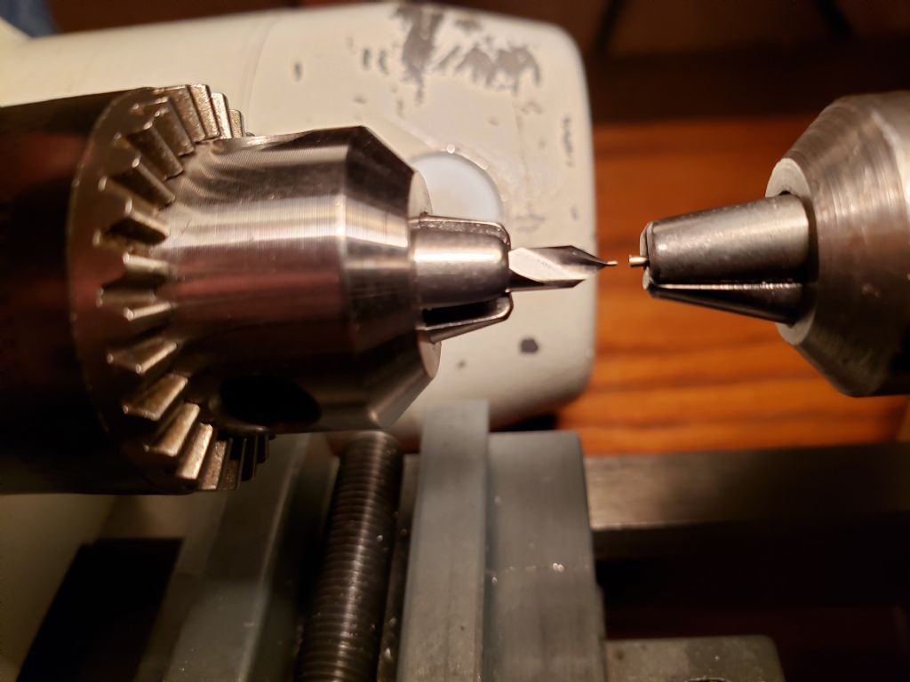
              I received the hypodermic tubing and center drill mentioned in the last post and made the insert. The following picture shows the center drill in one drill chuck and the insert extending out of another chuck. I use the center drill to make the 60 degree taper on the entrance of the insert. The next few posts will show some more pictures I made while working on and installing the insert.

              Insert Setup

              #463843
              Turbine Guy
              Participant
                @turbineguy

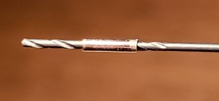
                The following picture is of the insert on the 0.022 diameter drill. This picture shows how tiny the insert is.Insert on Drill

                #463844
                DrDave
                Participant
                  @drdave
                  Posted by Turbine Guy on 09/04/2020 12:55:11:

                  …I also ordered a center drill with a 0.020 drill size and 60 degree included angle…

                  I didn’t realise that you can buy such a small centre drill “off the shelf”. Keep up the good work!

                  #463847
                  Turbine Guy
                  Participant
                    @turbineguy

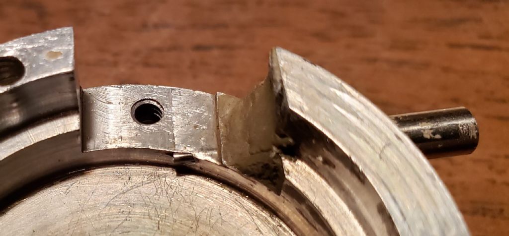
                    The following picture shows the insert starting into the existing nozzle hole of my Turbine housing. I apologize for the rough appearance of the housing. It had so many changes to try different ideas and has been assembled and disassembled so many times it shows all the scratches and wear. I will add an updated drawing showing the actual dimensions of the insert and its position in the existing nozzle in the next post.

                    Install Insert

                    #463849
                    Turbine Guy
                    Participant
                      @turbineguy
                      Posted by DrDave on 10/04/2020 21:36:02:

                      Posted by Turbine Guy on 09/04/2020 12:55:11:

                      …I also ordered a center drill with a 0.020 drill size and 60 degree included angle…

                      I didn’t realise that you can buy such a small centre drill “off the shelf”. Keep up the good work!

                      Hi Dave,

                      I can actually get a center drill with an 0.010 diameter drill size from McMaster-Carr. Thanks for the kind comment.

                      Byron

                      #463965
                      Turbine Guy
                      Participant
                        @turbineguy

                        I bonded the insert to the existing nozzle bore with Loctite 290 and allowed it to cure overnight. The following drawing shows the finished dimensions of the insert and the position in the existing nozzle bore. I started the cleanup of the Loctite and found it has got into a lot places I did not want it to get into. It will take me a while to finish the cleanup, but if I can't get the Loctite out of all of the flow path, the insert won't work correctly.Nozzle Insert 2

                        #464251
                        Turbine Guy
                        Participant
                          @turbineguy

                          I cleaned out the bore of the nozzle insert with a 0.022 in. drill and then cleaned the 0.032 in. diameter at the discharge end of the nozzle. I tried to clean the tapered entrance of the insert. Because of the metal filled epoxy I used to fill an opening where the drill broke through, I could not get a tapered pin down to the entrance of the insert. With the entrance taper still blocked with Loctite, the flow coefficient of the insert is reduced considerably. My original nozzle has a 60 degree included angle entrance and an estimated flow coefficient of approximately 0.93. With the tapered entrance of the insert partially blocked with Loctite, the flow coefficient is reduced considerably. I ran Turbine 3 with the APC 4×3.3EP propeller, Krytox GLC 105 oil, and 50 psig steam. The maximum speed was 4,150 rpm and the speed stayed approximately the same for 13 minutes until the boiler ran dry. The boiler had ¾ cup of water at the start of the test, so the mass flow rate was approximately 1.8 lbm/hr (19 g/min). The performance indicated that the larger diameter at the discharge end of the insert did not allow the steam to reach supersonic speed. Apparently, this was not one of my better ideas.

                          #466285
                          Turbine Guy
                          Participant
                            @turbineguy

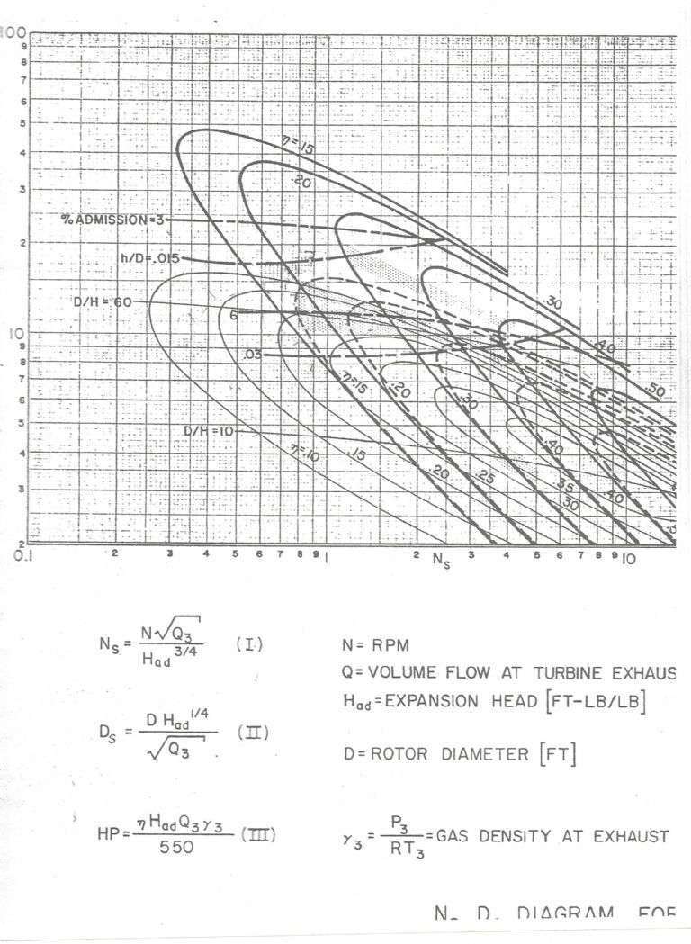
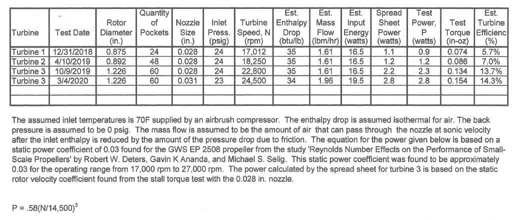
                            I just read Mike Tilby’s very informative Steam Turbines Large and Miniature Article 23. He generously included a reference to this thread. This article is on Stumpf-type (Terry-type) turbines. He correctly stated that I believe the open pockets can be as efficient as pockets with an outer wall, especially when the spacing between the rotor and the casing is very small. To back this up, I will compare the performance of the last test of my Turbine 3 running on air with the performance estimated from the following chart. This chart, also shown in the post of 14/03/2019, is copied from ‘A Study Of High Energy Level, Low Output Turbines’ prepared by Dr. O. E. Balje for the Department of the Navy in December 1957. This chart illustrates the maximum performance he estimated for various types of turbines when optimized. The heavy solid lines in the chart are for axial turbines. The dashed lines are for Terry turbines. The thin solid lines are for Drag turbines. The drag turbines are like turbine pumps. The blades circulate the flow in a way that increases the drag force on the rotor. The units for the volume flow are ft*3/sec and lb/ft^3 for the gas density. The values of Ns and Ds for Turbine 3 for the test of 3/4/2020 are 1.0 and 14.9 respectively. The efficiency of an optimized Terry turbine with these values of Ns and Ds from the chart is approximately 16% and the efficiency of Turbine 3 was 14.3% based on my most conservative values of the power required by the propeller. I’ll get into the Reynolds number effects and how they lower the efficiency of the optimum Terry turbine below that of my turbine for this particular case in the next post.Ns Ds Diagram

                            #466288
                            Turbine Guy
                            Participant
                              @turbineguy

                              The Reynolds number of my turbine for the test conditions shown in the table below and mentioned in the last post is 1.4 X 10^4. The minimum Reynolds number for the performance given in the chart shown in the last post is 2 x 10^5. The more viscous running conditions of my test compared to what was assumed making the chart, means that the viscous losses are higher than assumed in the chart. Dr. Balje gives an efficiency correction of 0.87 for the 1.4 X 10^4 Reynolds number. That reduces the efficiency of the optimum Terry turbine to 13.9% compared with Turbine 3’s estimated efficiency of 14.3% for this case with low Reynolds number, low pressure, low temperature, low speed, and low energy.

                              Turbine Test Results 5

                              Edited By Turbine Guy on 22/04/2020 12:27:41

                              #468099
                              Turbine Guy
                              Participant
                                @turbineguy

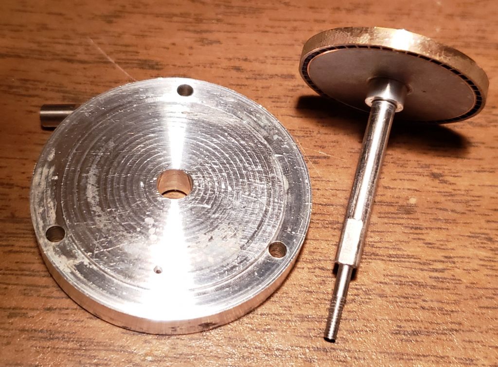
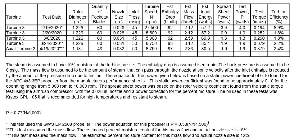
                                In the post of 07/03/2020 I mentioned that I had mounted one of Werner Jeggli’s cast axial turbine rotors to a shaft and made a cover plate with a nozzle so that I could test his rotor in my Turbine 3 housing. The following picture shows these parts. I ran this rotor on steam with a clearance of 0.031 in. between the face of the rotor and the face of the cover plate. With this clearance, the cast axial rotor had approximately the same power output as my machined tangential rotor. The updated test sheet shown below shows the results of that test. The next post will have a drawing showing the dimensions of the parts and the placement of the rotor in the housing for this test.

                                Axial Turbine 2 PartsTurbine Test Results 9

                                #468103
                                Turbine Guy
                                Participant
                                  @turbineguy

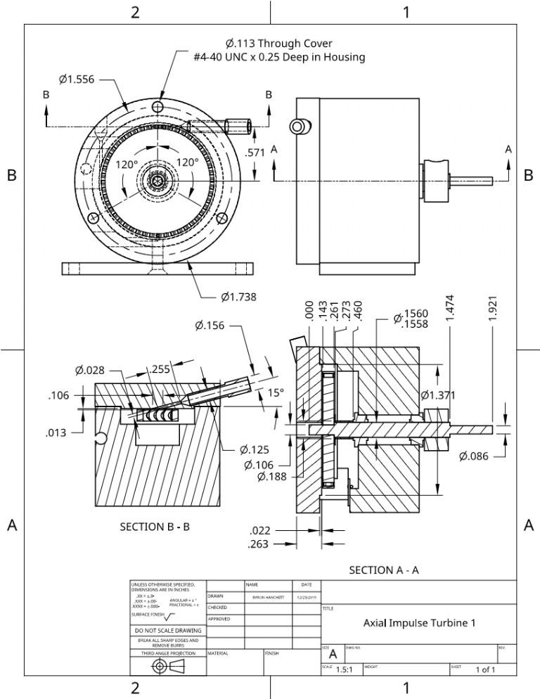
                                  The following drawing shows the mounting of the new cover plate and Werner's axial rotor described in the previous post in my Turbine 3 housing. The dimensions show the size of the rotor and cover plate and the position of the rotor for the test shown in the last post.

                                  Axial Turbine 2

                                  #468634
                                  Turbine Guy
                                  Participant
                                    @turbineguy

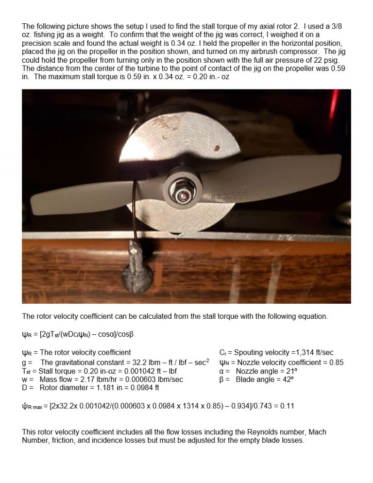
                                    I ran the following test to estimate the maximum stall torque and rotor velocity coefficient for the axial rotor using my airbrush compressor. This was done for the tangential rotor and shown in the post of 01/02/2020. Comparing the values found for the tangential rotor and the axial rotor, the axial rotor has a larger maximum stall torque (0.20 in-oz vs 0.18 in-oz) but only in the optimum positions. The nozzle was larger for the axial rotor (0.032 vs 0.028) which accounted for most of the increase in torque. The maximum torque stayed the same regardless of the position for the tangential rotor.

                                    Axial Turbine RVC

                                    #468888
                                    Turbine Guy
                                    Participant
                                      @turbineguy

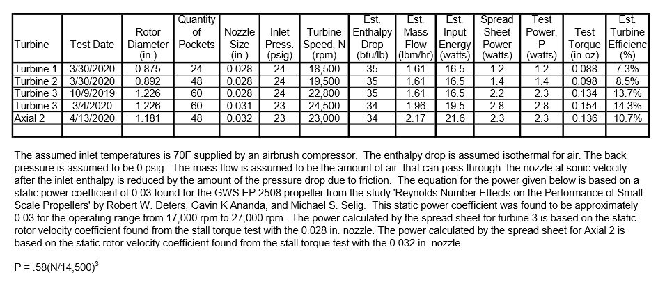
                                      I updated the following test results to include running the cast axial rotor on air. I also updated the performance of my Turbine 1 and Turbine 2 running on air. The only changes to Turbine 1 and Turbine 2 were finding the optimum position of the rotors and setting the collar clearance to 0.004 in. This updated the performance to the maximum values I have found optimizing the position of the rotor for the propeller being used. The ball bearings used in all these tests had the original oil supplied by the manufacturer (AeroShell Fluid 12) and had not been exposed to steam.

                                      Turbine Test Results 10

                                      #473924
                                      Turbine Guy
                                      Participant
                                        @turbineguy

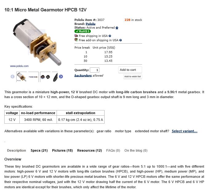
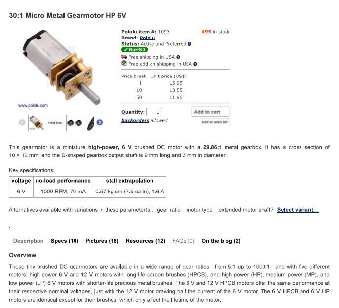
                                        I made an estimate of the performance of my Turbine 3 using a low cost gearbox with a 30:1 ratio. The gearbox shown below is part of a gearmotor and is capable of running with an input speed of up to 30,0000 rpm and can handle the torque of Turbine 3 running on air. All the gear shafts use the brass side plates for bearing surfaces, so the friction is high and the overall efficiency relatively low. I picked this gearbox since it is readily available and very low cost as shown below. It also has a performance sheet that will be shown in the next post. What I am trying to do is show my very simple turbine and a very low cost gearbox can be used at output speeds of model steam engines. I tested two model steam engines, a very simple oscillating cylinder steam engine and a more complex piston valve steam engine using my airbrush compressor. The tests are shown in the following thread https://www.model-engineer.co.uk/forums/postings.asp?th=139899. This thread has complete descriptions of the steam engines tested, the propellers used for the tests, and all the test parameters. The thread jumps back and forth between tests of turbines, steam engines, and many proposals for ways to improve them. If you have the patience to read through the entire thread you can see all the things I explored. In the next post, I will compare the estimated performance of my Turbine 3 using this gearbox with the performance of the steam engines.

                                        Pololu Gearmotor 3

                                        #473943
                                        Turbine Guy
                                        Participant
                                          @turbineguy

                                          I showed the wrong gearmotor in the last post. The following is the gearmotor that should have been shown.

                                          Pololu Gearmotor 5

                                          #474231
                                          Turbine Guy
                                          Participant
                                            @turbineguy

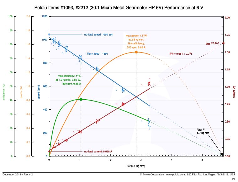
                                            The following chart shows the performance of the gearmotor shown in the last post. I will show the estimated performance of my Turbine 3 with the gearbox from this gearmotor compared with performance of the Stuart ST oscillating cylinder steam engine in the next post.

                                            Pololu Gearmotor 2

                                            #474265
                                            Turbine Guy
                                            Participant
                                              @turbineguy

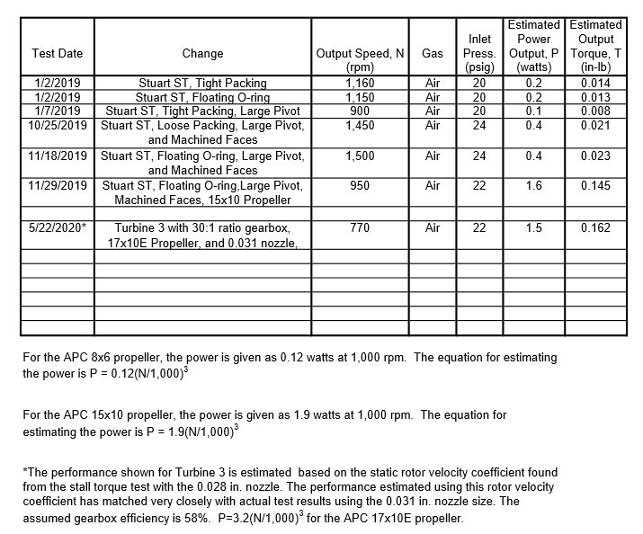
                                              The following chart compares the performance of Turbine 3 using the 30:1 ratio gearbox described in the preceding posts with the Stuart Turner ST oscillating cylinder steam engine. The data for the Stuart ST comes from the post of 26/10/2019 in the Testing Models thread shown in the following link https://www.model-engineer.co.uk/forums/postings.asp?th=139899&p=4. The data shown for the Stuart ST improved with the changes shown in the chart, so the comparison is between the optimized Turbine 3 and the optimized Stuart ST. The big change in performance of the Stuart St with the larger propeller was the result of the very small port opening area of this engine as described in the Testing Models thread. The propeller used with Turbine 3 was chosen to keep the output power to the maximum shown for the gearbox. Turbine 3 is capable of much higher power with a 30:1 ratio gearbox if the speed and power is not limited.

                                              Stuart ST vs Turbine 3

                                              #474498
                                              Turbine Guy
                                              Participant
                                                @turbineguy

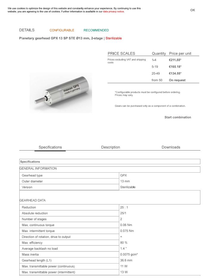
                                                In the last post I showed the estimated power my Turbine 3 could produce with a very low cost 30:1 ratio gearbox. With that gearbox, the estimated power for Turbine 3 running on my airbrush compressor was 1.5 watts. The power of a Stuart Turner ST oscillating cylinder steam engine modified to get the best performance I was able to obtain, reached a power of 1.6 watts with the same air pressure. The output at the low steam engine speeds for these is estimated to be about the same using this low cost speed reducer. The speed reducer shown below is much more expensive, but can run continuously at speeds up to 60,000 rpm and a maximum continuous power of 11 watts. I will show the estimated power of my Turbine 3 using this gearhead in my next post.

                                                Maxom Gearhead

                                                #474509
                                                Robert Atkinson 2
                                                Participant
                                                  @robertatkinson2

                                                  Have you though of using a small brushed DC motor as a dynamometer?
                                                  With a variable load you can check the power at various speeds and torque. The Torque is directly proportional to current regardless of speed. You can calibrate the motor / Dynamometer torque constant at stall using the weight / lever arrangement while supplying enough power to keep it balanced. A current reading gives you thedivied by the torque give you the constant for that motor. Using a brushed DC motor as a dynamometer you can get a pretty good estimate of the static or running torque and power. Most accurate is to meaure the speed and torque and do the math. Simply measuring the electrical power (V x A) will give a slightly lower figure but you can compensate by allowing for the voltage drop caused by the DC resistance of the motor.

                                                  Robert G8RPI.

                                                  #474516
                                                  gerry madden
                                                  Participant
                                                    @gerrymadden53711

                                                    Excellent to hear Robert, I never realised this was independent of speed ! Now I can check the efficiencies of some clock gear-trains and measure my improvements smiley

                                                    Posted by Robert Atkinson 2 on 24/05/2020 15:45:43:

                                                    ……….The Torque is directly proportional to current regardless of speed. ………….

                                                    #474543
                                                    Turbine Guy
                                                    Participant
                                                      @turbineguy
                                                      Posted by Robert Atkinson 2 on 24/05/2020 15:45:43:

                                                      Have you though of using a small brushed DC motor as a dynamometer?
                                                      With a variable load you can check the power at various speeds and torque. The Torque is directly proportional to current regardless of speed. You can calibrate the motor / Dynamometer torque constant at stall using the weight / lever arrangement while supplying enough power to keep it balanced. A current reading gives you thedivied by the torque give you the constant for that motor. Using a brushed DC motor as a dynamometer you can get a pretty good estimate of the static or running torque and power. Most accurate is to meaure the speed and torque and do the math. Simply measuring the electrical power (V x A) will give a slightly lower figure but you can compensate by allowing for the voltage drop caused by the DC resistance of the motor.

                                                      Robert G8RPI.

                                                      Hi Robert,

                                                      Werner Jeggli uses a simiiar scheme using a brushless DC servomotor testing his turbines. I prefer the simplicity of using the propellers that I can get test data for. The propellers are quite inexpensive and readily available and the results I have obtained using them show results I believe are just as accurate. The downside of using the propellers compared to using motors as generators is that you need a propeller correct for your application. The propeller I use testing my turbines with air gives me adequate results to compare changes or different turbines. Werner is way ahead of me testing with steam because he can operate his turbines at a much higher speed and adjust the load to optimum values. I have not been able to obtain a propeller with test data that can operate at speeds as high as the 35,000 rpm. This is the speed Werner is currently able run with adequate ball bearing life. I will use the Maxom gearhead to estimate the performance at this speed running on steam.

                                                      Thanks for the input,

                                                      Byron

                                                    Viewing 25 posts - 151 through 175 (of 562 total)
                                                    • Please log in to reply to this topic. Registering is free and easy using the links on the menu at the top of this page.

                                                    Advert

                                                    Latest Replies

                                                    Home Forums Stationary engines Topics

                                                    Viewing 25 topics - 1 through 25 (of 25 total)
                                                    Viewing 25 topics - 1 through 25 (of 25 total)

                                                    View full reply list.

                                                    Advert