Model Turbines
Model Turbines
Home › Forums › Stationary engines › Model Turbines
- This topic has 605 replies, 28 voices, and was last updated 9 June 2025 at 15:11 by
Turbine Guy.
-
AuthorPosts
-
17 August 2019 at 21:12 #424745
 Neil WyattModerator@neilwyatt
Interesting, what sort of 3D printing is it? Laser sintering?
Neil
18 August 2019 at 07:20 #424785Neil Lickfold
Participant@neillickfold44316How viable are ceramic bearings for turbines these days ?
Neil
18 August 2019 at 12:40 #424848Werner Jeggli
Participant@wernerjeggli14222Hello Turbine Guy,
I think, the ECOPARTS rotor of your design is valid. but it would require different nozzle designs. I will follow up this idea later on (age permitting). At present I'll concentrate on my old design. The power generated there is sufficient for our gauge 1 locomotives. Here are the results of the last tests:
(I've problems with inserting the link, hope it works)
I have also a problem with my precision lost wax caster. He did also the nozzle castings at reasonable prices. He seems to be out of business. Alternative suppliers are much more expensive.
Werner
18 August 2019 at 12:49 #424852Werner Jeggli
Participant@wernerjeggli14222Neil,
I do not think it is sintering. They call it "Additive Manufacturing". have a look at their homepage
http://www.ecoparts.ch/ ( switch to englisch language)
As to the full ceramic/hybrid ball bearings – both fail, but it seems to me that they fail much quicker when rigidly mounted in the test stand. I put the turbine now on rubber dampers. The turbine bearings in the existing locos hold up quite well.
Werner
Edited By Werner Jeggli on 18/08/2019 12:59:52
18 August 2019 at 18:14 #424904Turbine Guy
Participant@turbineguyPosted by Werner Jeggli on 18/08/2019 12:40:23:
I think, the ECOPARTS rotor of your design is valid. but it would require different nozzle designs. I will follow up this idea later on (age permitting). At present I'll concentrate on my old design. The power generated there is sufficient for our gauge 1 locomotives. Here are the results of the last tests:
**LINK**
(I've problems with inserting the link, hope it works)Hi Werner,
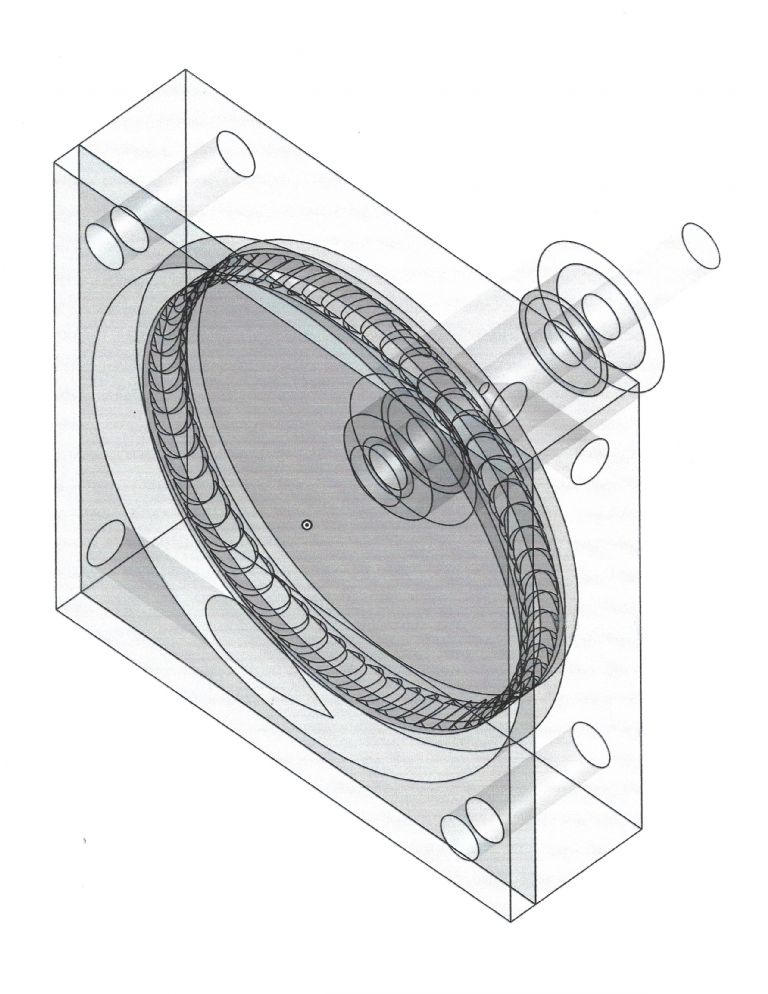
Thanks for trying to defend my design. Your link worked find for me and your test sheet showed you were able to get the 10 watt power you thought you could obtain. Your existing rotor design with the wider opening relative to the edge thickness might be one of the major reasons for its success. My design would require razor sharp edges and very smooth surfaces to obtain maximum performance. In one of my earlier posts I wondered why Jim Bamford changed from axial to tangential flow. I made the following solid model to illustrate how easy it is to get unobstructed flow in a tangential turbine. I think this might be one of biggest advantages for the overlapping pocket design of my tangential turbines.
18 August 2019 at 18:56 #424914Turbine Guy
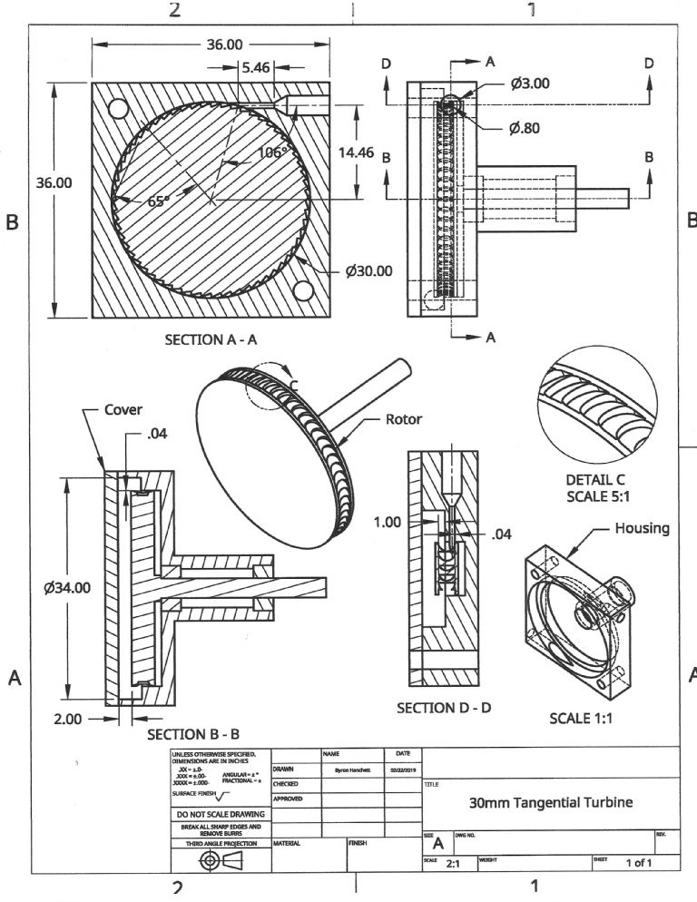
Participant@turbineguyThe following drawing shows the dimensions that I consider important for the design described in the previous post. The 5.46mm dimension shown in section A-A should be kept as short as possible to limit the friction losses of the supersonic flow. The 106 degree dimension shows about the practical minimum for the flow to not blow over the overlapping pockets. Since the flow deflects about 6 degrees with nozzles of this type the effective nozzle angle is about 22 degrees. The angle of 65 degrees yields a 25 degree pocket angle which is about right for the 22 degree nozzle angle and speeds around 30,000 rpm. The 0.04mm dimension in section B-B, and the 0.04 and 1.00 dimensions in section D-D are approximately what I had in my last turbine. The rest of the dimensions show the size of the parts and recommended clearances. The nozzles and rotors machined out of aluminum or brass have resulted in very smooth surfaces using common drills, mills and turning tools.
20 August 2019 at 21:09 #425251Turbine Guy
Participant@turbineguyA few days ago, I sprayed WD-40 into the ball bearings that had been gummed up by running my turbine on steam. I flipped the propeller with my finger and it spun fairly freely but there was some noise that wasn’t there before I ran on steam. I connected the air line from my airbrush compressor and ran the turbine with the same 1.65 bar air pressure I have used for all my tests with air. The maximum continuous speed obtained was 17,800 rpm with an estimated power of 2.2 watts. This was quite a bit less speed and power from the 3.9 watts at 21,500 rpm I got from this same air pressure before running the turbine on steam. The reduction in torque was approximately 5.6 g-cm. The torque at 21,500 with this pressure was 18.7 g-cm so the loss was very substantial.
31 August 2019 at 18:24 #426842Turbine Guy
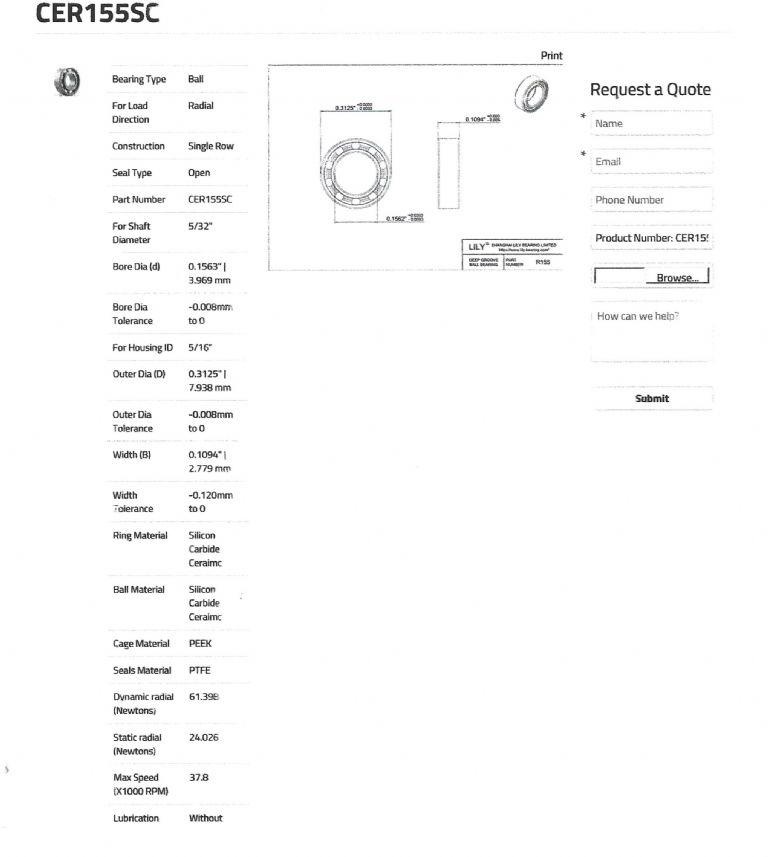
Participant@turbineguyI started to look at options for replacing the ball bearings I have been using for ones that would work running with steam. I would love to find a flanged extended inner race ball bearing with lubrication not effected by steam or water. I have found stainless steel ball bearings that have methods of lubrication that are water resistant but cannot tolerate the combination of high speed and temperatures around 100 C. The following print shows a full ceramic Lily ball bearing that is rated for the temperature and speed I need and they claim a flanged version is available. I requested a quote with and without the flange for a quantity of 4. If this bearing is available in this quantity and has a price I can afford, I’ll purchase some and test them on air and steam. It will be interesting to see if the full ceramic ball bearing with only condensate for lubrication has the same negligible friction that the lubricated ball bearings I have been using have. I would also like to see if they work with air.
2 September 2019 at 18:38 #427123Turbine Guy
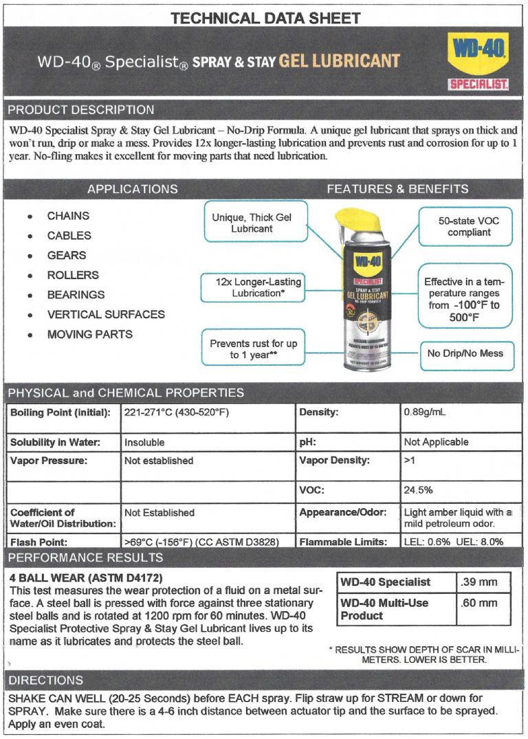
Participant@turbineguyI got the quote from Lily for the full ceramic ball bearings. The cost was US$95 per item for a quantity of 4 parts. This is approximately 10 times the amount I am paying for my existing bearings buying one at a time. I want to stay with ball bearings primarily due to the precise placement they allow. My best run has been with a clearance of approximately 0.04mm between the rotor OD and the housing ID. I don’t know if that tight of a clearance is necessary, but I don’t want to add more clearance unless absolutely necessary. Graphite bushings would work for the temperatures and speeds I require without adding too much friction when operating dry using my airbrush compressor. They would work even better with wet steam. The biggest problem for my existing turbine would be the extra clearance required for wear. I thought my existing bearings were lubricated with grease, but found that they used oil. I tried spraying both of the bearings in my turbine with WD-40 until they were soaked. I thought this might wash out the existing oil that had gummed up. After soaking the bearings with WD-40, I ran the turbine with my airbrush compressor. I got a speed of 21,200 rpm that was almost the same speed of 21,500 rpm I reached before running with steam. I went to the WD-40 website to see if they had anything better for my situation. Their Specialist Spray and Stay gel lubricant looked like it would meet my needs. The following is their technical data sheet. I ordered a can and will try it for both air and steam.
2 September 2019 at 19:41 #427137Mike Tilby
Participant@miketilby23489Hi Turbine Guy, very interesting discussion on bearings. One thought crossed my mind – previously I asked the company SMB Bearings for advice on use of their stainless steel bearings which are rated at 50,000rpm. I told them that I planned to run them at 50,000 rpm and they advised strongly against them because they said at that rated speed they would not last very long since the rated speed was the absolute maximum. I guess different manufacturers may mean different things when they specify a speed rating. So, if you've not asked them already and before paying a lot of money, I was just wondering if it is worth checking with Lily how their bearings would peform at the speed you plan to run at since it seems only slightly below the max. rating. SMB advised me to use bearings rated at 200,000 rpm for a 50,000 rpm turbine. The 200,00rpm bearings are hybrid – ceramic balls and s/s rings. [Apparently the key factor that wears out bearings at high speed is centrifugal force of balls against the outer ring. ceramic balls ar less dense than s/s balls and so the centrifugal forces are less].
Regards
Mike
2 September 2019 at 22:02 #427160Turbine Guy
Participant@turbineguyHi Mike,
Thanks for your feedback. My ball bearings are rated at 63,000 rpm and 250F temperature. My maximum speed with steam is 28,000 rpm and the housing with air blowing over it is probably not much hotter than 200F. With the low friction and relatively low speed, I doubt the temperature of the bearing is over the rated temperature. Part of what I liked with the special WD-40 was the oils higher temperature rating. All that being said, I ran my last turbine several times on air without adding lubrication and without losing any speed until I ran on steam. The moisture and/or the temperature apparently caused the problem. The run on steam stayed at approximately the same maximum speed until the pressure started to drop so I think it was the moisture not the heat that ruined the oil. My runs on air were only a couple of minutes each and my one run on steam was less than 20 minutes so I don’t have a very long total running time. The full ceramic bearing I got the quote for was with the materials rated for the highest speed and running without lubrication by Lily. I got to their website when looking for suppliers of dental turbine bearings. Their smaller bearings are capable of running at the dental turbine speeds with lubrication. If I have success using the special WD-40, I’ll run some longer tests to see how the bearings hold up.3 September 2019 at 14:54 #427273Mike Tilby
Participant@miketilby23489Hi Turbine Guy
63,00 rpm does sound good. My comment was triggered by the max speed of 38,700rpm shown on the data sheet you posted for the CER155SC bearings. Since the dental bearings I've bought (but not used yet) can run dry or lubricated with water, they should avoid problems of oil and its emulsification. But I am still thinking of trying graphite initially, especially in view of the information you provided about its durability. Unfortunately I am still a long way from getting to the stage of experimenting with bearings.
Mike
5 September 2019 at 18:21 #427669Turbine Guy
Participant@turbineguyI tried spraying the special WD-40 on the shielded ball bearings hoping the spray would get by the shields and form the gel inside the bearings. I ran the turbine with the airbrush compressor after allowing time for the lubricant to thicken. When I started the turbine, the maximum speed was only about 10,000 rpm and after running for several minutes reached a speed of approximately 20,000 rpm. This was what I assumed would happen since the gel has to spread around enough to let the ball bearings run freely. I ran the turbine with the airbrush compressor for another 12 minutes to see if the turbine would maintain a constant speed. The turbine would run for several minutes at approximately 20,000 rpm and then slow down and go back to the maximum speed. It slowed down several times but always went back up to the maximum speed. When the turbine slowed down it was fairly abrupt and it would pick up speed very quickly afterward. There were also some strange sounds that I hadn’t heard before. I think I will try getting a new set of bearings and running them for an extended time with the airbrush compressor and see how they perform.
6 September 2019 at 16:50 #427816Turbine Guy
Participant@turbineguyPosted by Mike Tilby on 03/09/2019 14:54:47:Since the dental bearings I've bought (but not used yet) can run dry or lubricated with water, they should avoid problems of oil and its emulsification.
Hi Mike,
Can you share with us the source and part or model number of the bearings you bought? Also any more information on these bearing you can provide would be greatly appreciated.
I tried running my other turbine I call turbine 2 with my airbrush compressor. The bearings in this turbine have been used for all my tests with turbine 2 and for turbine 3 until I got a new pair of bearings right before the turbine 3 tests I posted for steam and air. These bearings had been added and removed in both turbine 2 and turbine 3 several times while I made runs to find the optimum number of shims to position the rotor. Although the total running time is not huge, it represents about as much as I would do in a year. My goal was to optimize each turbine and then just run them when I feel like it. I ran my airbrush compressor until it started to get hot (about 12 minutes). The speed stayed constant at about 18,300 rpm which was about the maximum I got after all my previous testing, so the performance hasn't changed. Also the friction is so low that when the rotor stops spinning, it will reverse itself and go to the exact same rest position. I don't have near as much running time with the higher speed of 21,500 rpm achieved with turbine 3, but it appears running around 18,000 rpm with air won't be a problem. Before I do anything else to turbine 3, I'll add new ball bearings and see if I can sustain the higher speed running on air.
6 September 2019 at 18:07 #427824Mike Tilby
Participant@miketilby23489Hi Turbine Guy
This is the company: http://www.smbbearings.com
They are in Oxfordshire, UK
They have been very helpful and had no minimum order size. This is the advice they sent me (it was a few years ago, so the price info will be out of date):
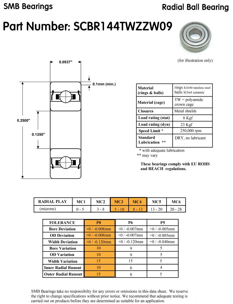
"My manager has recommended that you consider a dental bearing that we have available, with a high speed cage & ceramic balls – the SCBR144TWZW09 SMB – which can operate at 250000rpm without the need for lubrication (dimensions are 0.125×0.25×0.1094&rdquo
 . We currently have 14pcs available from stock at £9.48 each plus VAT."
Below is the data sheet for those bearings.
Regards
Mike
6 September 2019 at 20:22 #427833Turbine Guy
Participant@turbineguyHi Mike,
Thanks for sharing this information. If SMB recommended these for a speed of 50,0000 rpm, they should work fine for my turbines. Their price, even with increases, is still very reasonable. This would be a better alternative for my turbines than graphite since precise positioning is very important with my design. After I get my reversing chamber made and tested or I have problems with my existing bearings at the higher speeds, I might try using these in turbine 3.
12 September 2019 at 16:22 #428723Turbine Guy
Participant@turbineguyI got my new ball bearings for turbine 3. I Installed the new bearings and ran turbine 3 with my airbrush compressor. The speed gradually went up to 22,000 rpm and ran at that speed for a few minutes and then dropped in speed for a very short time and went back up to approximately the same top speed. The speed stayed at about 22,000 rpm for the rest of the first 5 minutes run. The second and third 5 minutes runs were similar. On each run the turbine would slow down and go back to maximum speed at least once. But on each run a speed of approximately 22,000 rpm could be maintained. I don’t know if the oil in the bearings has to spread out on each run before it settles into a constant speed or if something else is causing the temporary drop in speed. I never made any runs over a few seconds in all my testing of turbines 2 and 3 on air so maybe this is normal until the bearings get broken in. I think it is safe for me to assume the bearings are working okay and start to make my reversing chamber.
13 September 2019 at 19:15 #428864Turbine Guy
Participant@turbineguyPosted by Mike Tilby on 06/09/2019 18:07:49:
Hi Turbine Guy
This is the company: http://www.smbbearings.com
They are in Oxfordshire, UK
They have been very helpful and had no minimum order size. This is the advice they sent me (it was a few years ago, so the price info will be out of date):
Hi Mike,
The following is the quote I just received from SMB. The bearing they quoted you is still available and my cost for a quantity of 4 is less than what they quoted you a few years ago. This was the only hybrid bearing they could supply in low quantities close to the size I needed. This bearing will require quite a few changes to my turbine housing and rotor so I will probably try graphite before I try this bearing. SMB was extremely helpful and responsive and I think this is a great choice for someone looking for a bearing that can resist steam.
We can currently offer 4pcs SCBR144TWZW09 SMB stock at GBP£8.14 each & your delivery options are:
Insured airmail GBP£8.00 (5-15 days)
FedexPak Express GBP£14.35 (2-3 business days)
If the prices are of interest & you’d like to place an order, we welcome payment by bank transfer or PayPal (I will send you the appropriate invoice by email – PayPal incurs a 5% surcharge to cover their fees).I made several short runs with my turbine and the top speed with my airbrush compressor is now 22,300 rpm with the new ball bearings. This is about 800 rpm higher than I got with the old bearings. I thought that the friction was negligible with the old bearings so I can't understand why the turbine is running so much faster. The only change was the ball bearings. I didn't change any other parts or positions of parts. The power required by the propeller for the 22,300 rpm speed is estimated to be 4.4 watts. The power required by the propeller for the 21,500 rpm previous maximum speed is estimated to be 3.9 watts. That's an estimated 0.5 watt increase. Apparently, the effects of the lubrication are much larger at high speeds than at low speeds. It took several seconds for the turbine to coast to a stop after the air was shut off with the old bearings. I will use the 22,300 rpm top speed and 4.4 watt power as my new base for checking the effects of the next changes to my turbine 3.
29 September 2019 at 20:32 #431093Turbine Guy
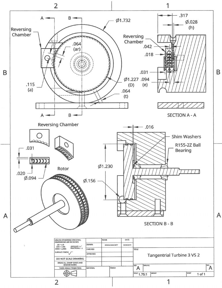
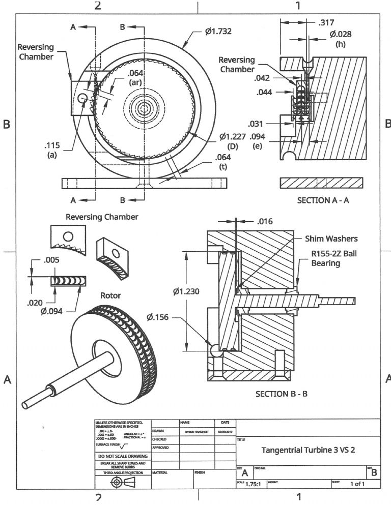
Participant@turbineguyThe following drawing is the first revision for turbine 3 with the velocity staging. As you can see there are quite a few changes from the drawing shown in the post of 10/04/2019. Some changes were made to improve the design while others were to repair errors in machining. The letter A was added to drawing file name to show this is revision A. This drawing shows the dimensions important for setup and analysis and shows the actual part dimensions at the time of this revision. I ran the turbine with and without the reversing chamber and will describe the performance in the next posts.
29 September 2019 at 20:51 #431096Turbine Guy
Participant@turbineguy30 September 2019 at 20:28 #431256Turbine Guy
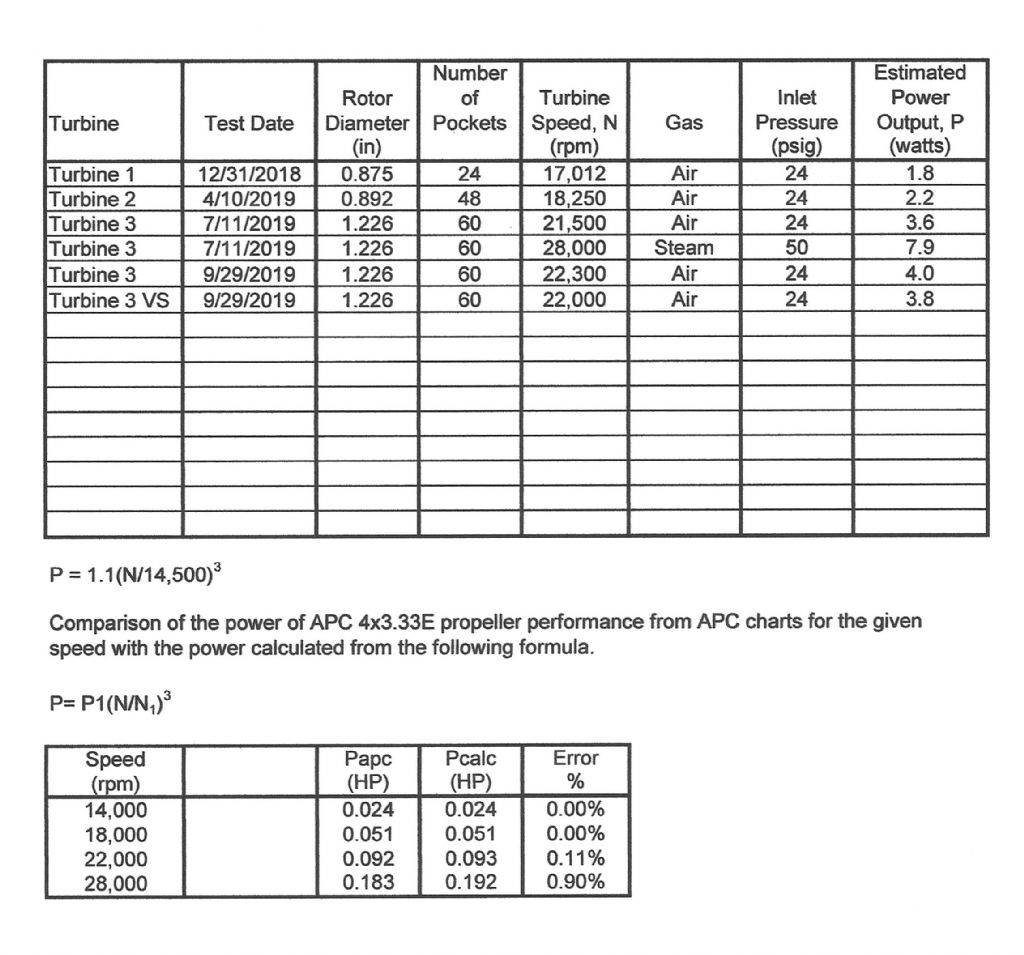
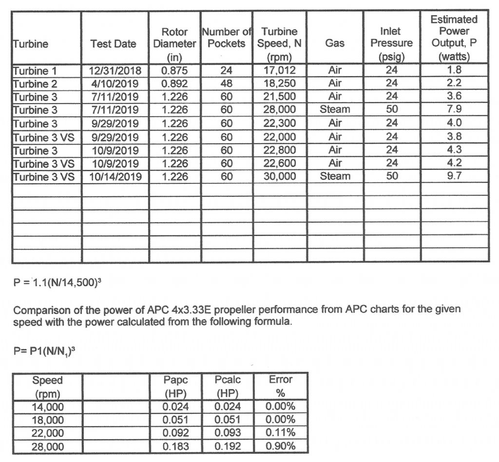
Participant@turbineguyI made the following chart to summarize the testing of my turbines and a chart at the bottom to check the validity of my equation for estimating the power required by the EP2508 propeller. I had only one speed of the EP2508 propeller that I could verify the required power. I wanted to see if my use of increasing the propeller power by the cube of the turbine speed was valid for the range of speeds of my tests. Since APC has performance charts for all its propellers, I checked the performance of their propeller closest in size to my EP2508 propeller at the speeds nearest to the speeds obtained in testing. As shown in the chart, increasing the power by the cube of the speed for the range from 14,000 to 28,000 rpm was accurate to within 1%. Since the first test was with Rulon bushings and run with a smaller boiler, I did not include its performance in this chart. This way all the tests on air or steam will be with the same airbrush compressor or boiler and all the turbines have the same ball bearings. I had mentioned earlier that I thought my estimates for power appeared it be optimistic. I lowered the estimated powers in this chart slightly from what I have previously given to be more conservative. These values of power are approximately the power I calculate using Dr. Balje’s guidelines. The first test with velocity staging resulted in lower power than with the reversing chamber removed. This is comparing an optimized single stage with the first try of velocity staging. Hopefully by optimizing the reversing chamber I can improve the performance of the velocity staging.
Edited By Turbine Guy on 30/09/2019 20:38:02
14 October 2019 at 21:54 #433357Turbine Guy
Participant@turbineguyThe following chart is updated to give the latest performance of my Turbine 3. The drawing showing the changes that gave me the best results will be added in the next post. I ran several tests with air after I got the maximum performance with all the changes I tried. The results stayed the same for both with and without the reversing chamber. The improvement in performance running on air was very small. The speed increased by 500 rpm without the reversing chamber and 600 rpm with the reversing chamber with the improvements. The turbine still made slightly more power without the velocity staging running on air. Apparently, the back pressure caused by the second stage was enough to keep the performance from getting better than with a single stage.
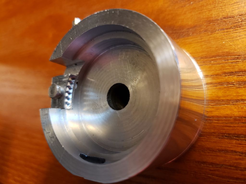
I ran the velocity staging with steam today and added the performance of this test to the table. The extra energy of the steam allowed the velocity staging to work better. The boiler pressure was the same as the test of 11/7/2019 without velocity staging, so the energy supplied should be approximately the same. The velocity staging with steam got a 1.8 watt increase in power. I planned on running on air immediately after running on steam to see if that would keep the ball bearings from gumming up. Even after releasing the hose clamp, the silicon hose I used for steam would not come off. I pressed the hose from my airbrush compressor against the silicon hose and got enough pressure to spin the turbine and blow the water out. I then tried pulling as hard as I could on the silicon hose. The stainless steel (ss) tube that was Loctited to my turbine housing popped out. I had to cut the silicon hose to remove it from the ss tube. I don’t know what caused the silicon hose to bond to the ss tube. I Loctited the ss tube back on my turbine housing and will run the turbine on air tomorrow after the Loctite cures. Hopefully, the ball bearings will not gum up.14 October 2019 at 22:07 #433361Turbine Guy
Participant@turbineguyThe following drawing shows some of the important dimensions of my Turbine 3 after getting the best performance I was able to obtain with velocity staging. Making the outer edge of the reversing chamber as thin as possible made the biggest improvement. This opened up the space for the steam or air exiting the second stage.
16 October 2019 at 18:51 #433565Turbine Guy
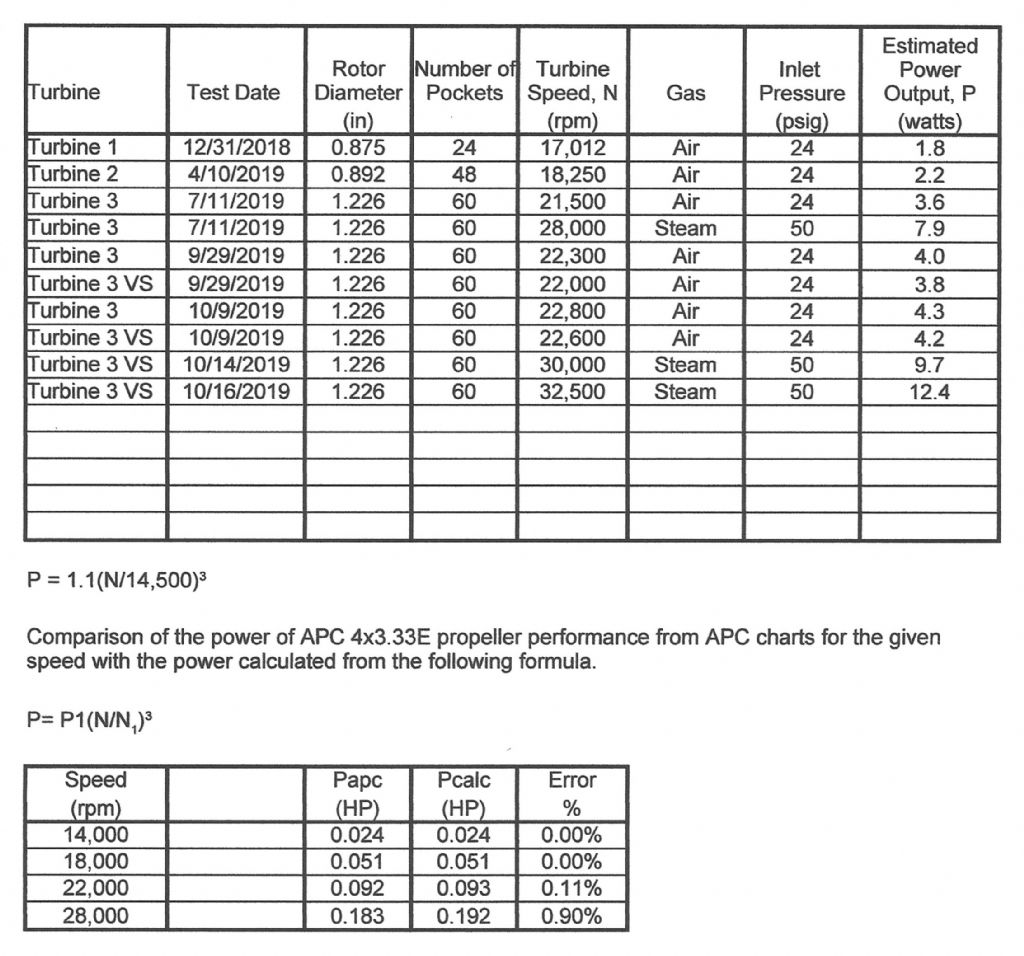
Participant@turbineguyI ran Turbine 3 on air after Loctiting the stainless steel inlet tube back on the housing. The speed never got back to the speed the turbine was running with the reversing chamber installed but my airbrush compressor was shutting down periodically. This indicated the turbine nozzle was partially blocked. I cleaned out the nozzle and ran the turbine on air again. The speed of the turbine went back to the same maximum speed it had before with velocity staging. Running the turbine on air immediately after running on steam appears to keep the ball bearing oil from gumming up. I wasn’t sure if the blockage in the nozzle occurred before or after the run on steam so I ran the turbine on steam again. After cleaning out the nozzle, Turbine 3 reached a maximum speed of 32,500 rpm with velocity staging. The resulting power of 12.4 watts was about what I hoped I would be able to achieve with velocity staging. This is an increase in power of approximately 4.5 watts with velocity staging. This increase in power is a little misleading. It should be pointed out that if the turbine was turning a load that could be adjusted like the motor running as a generator used by Werner in his testing, the power without velocity staging of Turbine 3 would be around 11 watts at 32,500 rpm. The power added by the velocity staging would be approximately 1.5 watts compared with the power that could be achieved at this speed without velocity staging. Using a propeller for the load results in the speed being set by the torque required to turn the propeller. The speed was very consistent during the short run on steam. Also, the relief valve on the boiler was constantly releasing steam so the pressure of 50 psig (3.4 bar) was the maximum the boiler could produce. I ran Turbine 3 on air after the run on steam and the maximum speed obtained was 22,600 rpm so the friction of the ball bearings has not changed. I am very pleased with the performance of Turbine 3 running on steam with velocity staging. The following chart is updated to show this test.
Edited By Turbine Guy on 16/10/2019 19:02:11
7 December 2019 at 18:42 #440679Turbine Guy
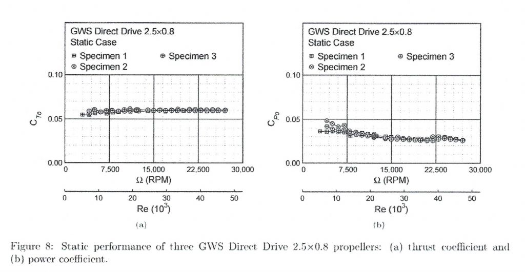
Participant@turbineguyI tried running an APC 4×3.3EP propeller on my turbine 3 to see if I could confirm my estimates of power. The speed I obtained both with and without the reducing chamber was 4,250 rpm running on air from my airbrush compressor. The actual power of approximately 0.5 watts I obtained using the performance chart for that propeller was about half or what I estimated. I had to make a lot of assumptions in the estimated power for the GWS EP2508 propeller, so I searched the internet for some actual test results for this propeller. I found a report titled Reynolds Number Effects on the Performance of Small-Scale Propellers. In that report I found the charts shown below for the actual performance of the GWS EP2508 propeller running in the speed range of most of my testing. The static power coefficient Cpo for the speeds ranging from 10,000 to 25,000 rpm was approximately 0.03 from fig. 8 chart (b). With this value of power coefficient, the power at 14,500 rpm is approximately 0.58 watts. This power is about half of what I estimated for this speed. I compared the values for the power coefficient from this report with values from APC for one of the tested propellers and they were almost identical, so I think the APC charts are valid. The report indicates that my estimates for the power using the GWS EP2508 propeller is almost double the actual power. Because my testing indicated that the gains in performance with each change matched what Dr. Balje’s methods estimated for the change, I went back to his Study of High Energy Level, Low Power Output Turbines to see if I missed something. In this report he states that the profile losses and consequently the overall losses, is almost doubled by decreasing the Reynolds number by a factor of 4 from the assumed value of 2 x 10^5. I had assumed that the Reynolds number effects were included in the equation I used for the estimated efficiency. I found this equation doesn’t include the effects of Reynolds number. When I corrected my estimated performance for the effects of the Reynolds number, the estimated power was approximately what the APC chart and the report Reynolds Number Effects on the Performance of Small-Scale Propellers gave. This was true for all the tests except the tests with the GWS EP2508 propeller running on steam. Those tests had speeds above 28,000 rpm which was outside the range the actual power coefficients were given. It takes a combination of a very low power input and very small dimensions to get this low of a Reynolds number but all my testing on air was in that range I will add the updated chart showing the new lower values of power in my next post.
-
AuthorPosts
- Please log in to reply to this topic. Registering is free and easy using the links on the menu at the top of this page.
Latest Replies
Home › Forums › Stationary engines › Topics
-
- Topic
- Voices
- Posts
- Last Post
-
-
Pattern Makers Vice
Started by:
 Vic
in: The Tea Room
- 3
- 3
-
2 July 2025 at 02:08
 peak4
peak4
-
Motor won’t start
Started by:
Rowan Sylvester-Bradley in: Beginners questions
- 6
- 6
-
1 July 2025 at 23:52
noel shelley
-
Meddings MF4 Manual
Started by:
Richard Kirkman 1 in: Help and Assistance! (Offered or Wanted)
- 10
- 20
-
1 July 2025 at 23:42
JohnF
-
Speed camera
Started by:
 David George 1
in: The Tea Room
- 14
- 16
-
1 July 2025 at 23:25
Nigel Graham 2
-
J&S grinder – belt which way ?
Started by:
gerry madden in: Manual machine tools
- 5
- 6
-
1 July 2025 at 22:53
Chris Crew
-
IME Watchmakers lathe
Started by:
Greensands in: Manual machine tools
- 11
- 16
-
1 July 2025 at 21:41
Dave S
-
Request for a Slot to be Milled in a Shaft
Started by:
James Alford in: Help and Assistance! (Offered or Wanted)
- 9
- 18
-
1 July 2025 at 21:03
bernard towers
-
Bearing boxes for ball race
Started by:
Paul McDonough in: Beginners questions
- 9
- 17
-
1 July 2025 at 21:02
Paul McDonough
-
Twin Engineering’s heavy mill/drill quill removal
Started by:
Martin of Wick in: Manual machine tools
- 7
- 9
-
1 July 2025 at 20:51
Martin of Wick
-
The Stevenson Trophy – Entries Invited
Started by:
 Neil Wyatt
in: Website Announcements
- 1
- 2
-
1 July 2025 at 18:44
 Neil Wyatt
-
The Bradford Cup – Nominations Wanted
Started by:
 Neil Wyatt
in: Website Announcements
- 1
- 2
-
1 July 2025 at 18:41
 Neil Wyatt
-
FreeCAD v1.0 tutorials
1
2
3
Started by:
 Michael Gilligan
in: CAD – Technical drawing & design
- 12
- 54
-
1 July 2025 at 18:31
Speedy Builder5
-
Haining vertical dairy engine boiler.
Started by:
apprentice in: Beginners questions
- 2
- 2
-
1 July 2025 at 18:26
 JasonB
-
All things Beaver Mill
1
2
…
8
9
Started by:
Robert James 3 in: Manual machine tools
- 43
- 208
-
1 July 2025 at 18:22
Charles Lamont
-
Dial test indicator vs Dial indicator
Started by:
martian in: Workshop Tools and Tooling
- 17
- 24
-
1 July 2025 at 16:59
Clive Foster
-
Help for DIY lathe build.
1
2
Started by:
moogie in: Help and Assistance! (Offered or Wanted)
- 16
- 32
-
1 July 2025 at 15:21
David Senior
-
Firth Valve Gear
Started by:
Andy Stopford in: Traction engines
- 9
- 18
-
1 July 2025 at 12:59
Nigel Graham 2
-
M type top slide conversion??
Started by:
jimmyjaffa in: Beginners questions
- 7
- 11
-
1 July 2025 at 11:35
 David George 1
-
Offen screw type telescopic gauge.
Started by:
Graeme Seed in: Workshop Tools and Tooling
- 4
- 9
-
1 July 2025 at 10:41
Graeme Seed
-
2 Machine lights
Started by:
modeng2000 in: Workshop Tools and Tooling
- 2
- 6
-
1 July 2025 at 08:57
Dalboy
-
New member looking for help
Started by:
 manfromthemist
in: Introduce Yourself – New members start here!
- 11
- 24
-
1 July 2025 at 08:19
Juddy
-
Wiring up a single phase AC motor with 4 wires
Started by:
ell81 in: Beginners questions
- 6
- 8
-
30 June 2025 at 19:49
Howard Lewis
-
New (old!) member
Started by:
iansoady in: Introduce Yourself – New members start here!
- 3
- 3
-
30 June 2025 at 19:30
Howard Lewis
-
Boiler Design – issue 4765
1
2
…
7
8
Started by:
Charles Lamont in: Model Engineer & Workshop
- 26
- 178
-
30 June 2025 at 12:58
Paul Kemp
-
High strength 4mm steel?
1
2
Started by:
iansoady in: Materials
- 20
- 31
-
30 June 2025 at 10:55
JohnF
-
Pattern Makers Vice
-


 . We currently have 14pcs available from stock at £9.48 each plus VAT."