Model Turbines
Model Turbines
Home › Forums › Stationary engines › Model Turbines
- This topic has 605 replies, 28 voices, and was last updated 9 June 2025 at 15:11 by
Turbine Guy.
-
AuthorPosts
-
13 April 2019 at 18:31 #404933
Turbine Guy
Participant@turbineguyDrDave,
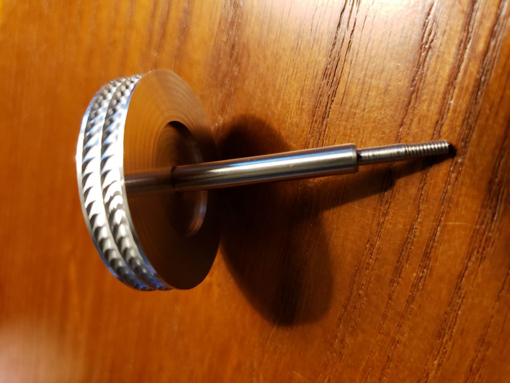
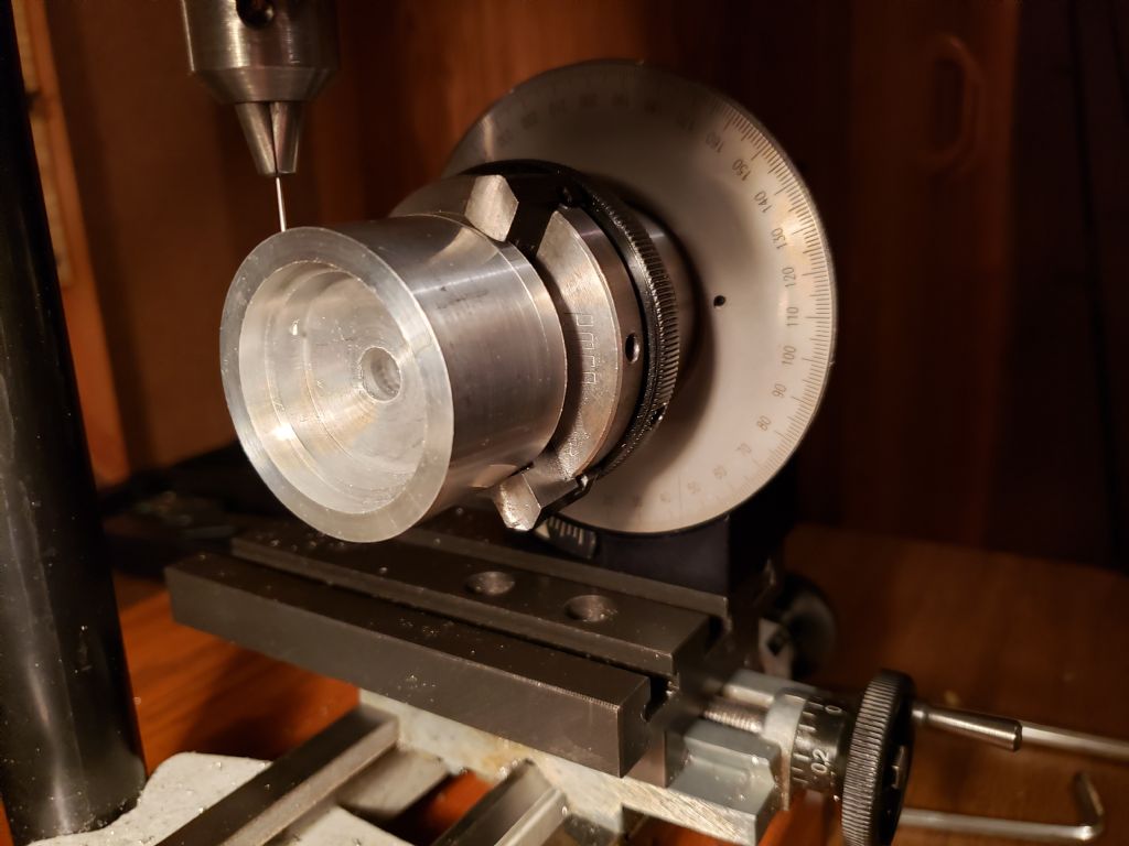
Thanks for your kind remarks. I hope the new turbine meets my expectations. I’ll start turning out the parts when the indexer I ordered arrives.
Martin,
The with ejector and without ejector analysis was an interesting project. I didn’t have any idea what the results would be. I hope this answered your question.The last test of my turbine with the new rotor had a Specific Speed Ns of 0.7 and a Specific Diameter Ds of 11.9. From the Ns Ds chart the adiabatic efficiency of the optimum axial impulse turbine is about 15% for these values. The adiabatic efficiency of my model turbine was approximately 13%. My design is relatively simple to make and I am pleased it gets this close to the performance of a well designed axial turbine.
I’m anxious to see how well the Curtis type velocity staging works with my open pocket design. I believe the momentum of the air will keep the flow against the pockets until it is almost through the rotor. I feel the very short flow length is what allows the open pockets to work.
18 April 2019 at 21:56 #405640Turbine Guy
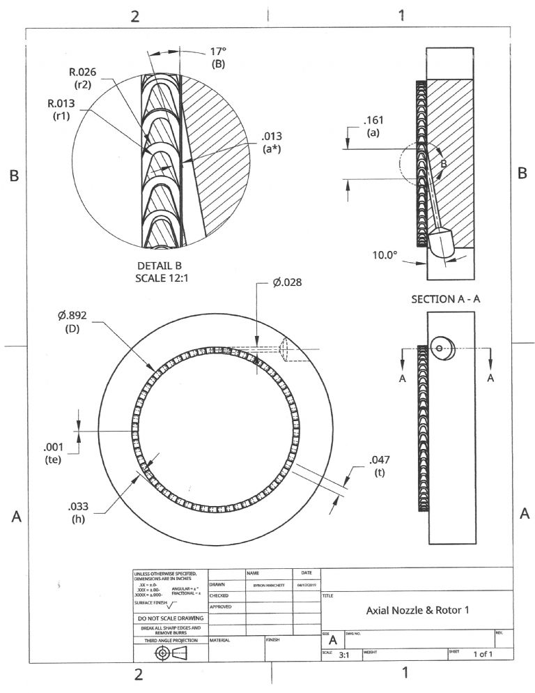
Participant@turbineguyI looked at the axial rotor and nozzle that would give the efficiency given in the last post. The rotor and nozzle assumptions used by Dr. Balje in the Ns Ds Diagram are:
a*/D = 0.015, s/h = 0.02, t/te = .02, and r1= a*. The cutter diameter (a*), blade height (h), blade pitch (t), blade entrance thickness (te), and the blade inside radius (r1) are shown in the following drawing. The clearance between the top of the blades and the housing (s) would need to be about 0.001 in. Another assumption is the flow leaving the nozzle should be at 16 degrees including the 6 degrees it deflects due to the angular discharge opening. The blade inlet and discharge angles are equal and designed to have no incidence at design speed. The drawing shows the values of these parameters for Ns = 0.7 and Ds = 11.9 of the last post. The speed (N) is 18,250 rpm, the exhaust volume flow (Q3) is 0.0064 ft^3/sec, and the expansion head (Had) is 27,230 ft-lb/lb for this example.
One of the most significant advantages of the axial turbine compared with the tangential turbine is the small angles that can be used on the nozzles and blades. The efficiency increases due to the flow being closer to perpendicular to the direction of the rotor movement and the increase in admission length (a). The tangential turbine is very limited in making the blade and nozzle angles small. Dr. Balje assumed a nozzle angle including the 6 degrees of flow deflection of 20 degrees for the Terry turbine.
 28 April 2019 at 16:27 #406911
Turbine Guy
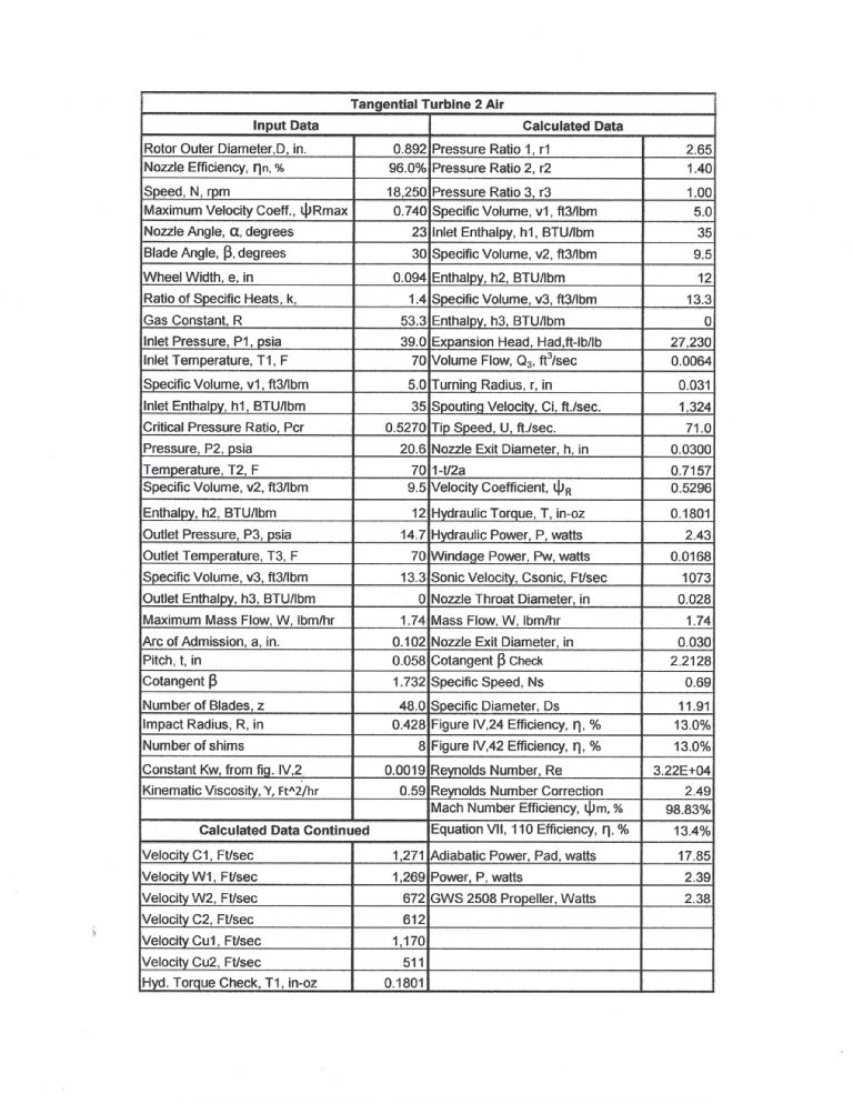
Participant@turbineguyThe following picture of my Excel spreadsheet shows how I document the performance from my testing and compare the results with the guidelines given by Dr. Balje. This is the spreadsheet I made for the tangential turbine described in the post of 26/03/2019. I can check the estimated performance with the actual performance using this spreadsheet. The spreadsheet shows the pressures, temperatures, and mass flow of the air used in the test and the estimated and actual performance with these values. The spreadsheet also shows all the applicable turbine dimensions used in the calculations. The spreadsheet includes the estimated velocities of the air at each stage of its passage from the nozzle through the rotor. Fig. IV.24 is the Ns Ds diagram for axial turbines with approximately 40 blades and Fig. IV.42 is the Ns Ds diagram for Terry turbines with approximately 40 blades from Dr. Balje’s report. The Ns Ds diagram shown in the 14/03/2019 post is for axial turbines with approximately 66 blades.
12 May 2019 at 23:09 #409014Werner Jeggli
Participant@wernerjeggli14222Gentlemen,
I just hit upon your thread – and I'm very interested. Obviously, you are all professionals and I'm trying to follow your arguments. But I'm confused! You started out with the idea of a steam turbine. But in the later posts, the discussion is based on air turbines – right ? That are totally different kettles of fish.
I think that your method of measuring the turbine output is not very accurate. Using a brushless generator gives you shaft power and rpm – see ME Vol.207, No.4412, September 2011 (Dampfsprinter) and ME Vol 215, No.4514 (Turbomotive). There, I also tried to determine turbine efficiency.
My latest project, the PRR-S2 is also quite successful (search YouTube under "PRR-S2, Jeggli"
 . The good performance I reached more or less by trial and error. I'd love to get them supported by a more scientific approach. The problem is the turbulent steam flow in the turbine. I do not think to being able to build a more efficient multistage turbine, reducing the pressure drop to the required 0.8 Bar/stage, which would insure laminary steam flow.
At present I'm working on a lost wax cast turbine design, hopefully delivering 10 Watt shaft power at 35'000 rpm.
13 May 2019 at 15:01 #409090Turbine Guy
Participant@turbineguyThank you for your post Werner. This thread was intended to share information on model turbine designs for air, steam, or any other medium. In the case of my model turbine it has run on both steam and air. I prefer to do the testing on air since the output of my airbrush compressor is more consistent and it is much easier to set up and run.
I don’t know how the accuracy of measuring the power with a brushless generator compares with using a propeller. Both require a means of measuring the speed and require the efficiency of the measuring devices. I use a laser speed sensing device that has a +/- 0.05% accuracy. I found the volts and amps used by an electric motor to turn the EP2508 propeller I use at a speed approximately the same as my turbine test speed. The manufacturer of the electric motor gave the efficiency of the electric motor at about the same speed. I used the power the propeller required to run at the given speed as a base. I assume the efficiency of the propeller and the electric motor is relatively constant for a small range of speeds. The range of speeds for the tests I have done with this propeller is from 14,500 rpm to 18,250 rpm. The speed of the propeller in the test with the electric motor was 15,600 rpm. I don’t have access to the ME reports you mentioned, but I am very interested in any information you can give on better methods of testing.
I watched the You Tube testing of your PPR-S2 project and was very impressed by the performance of you model train. I am very interested in the details of the turbine used in this project and would appreciate any detailed information you can provide.
Good luck with your next project.15 May 2019 at 20:40 #409392Werner Jeggli
Participant@wernerjeggli14222David Carpenter approached me about an input for his modelengineeringwebsite.com . I sent him details of my past contributions to the SMEE Journal. I hope, David will tell us when they will be online.
On my side, I would love to hear about any other successful model steam turbine application – with pictures/videos and performance data if possible.
15 May 2019 at 20:54 #409396Turbine Guy
Participant@turbineguyWerner,
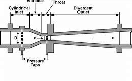
A friend was able to send me a copy of the LMS Turbomotive article. To say the article was impressive is an understatement. You should be very proud of this accomplishment. About the only place I believe I can help is with the turbine nozzles. For the 200 Ws/g turbine energy input you showed in the article, the nozzle discharge velocity is supersonic. Supersonic nozzles require a converging inlet section and a diverging outlet section similar to the following picture. The higher the mach number gets, the more unstable the flow becomes. You have an additional complication with the wet steam. The wet steam will cause the flow to be two phase, liquid and gas. Your article doesn’t show the design of your nozzles, but if you are using a simple converging nozzle like I am, you will need to make a supersonic nozzle to get stable performance with your turbine energy input. My boiler has a pressure of approximately 1.7 bar and a steam temperature of 193 C. The turbine energy input from my boiler is 63 btu/lb (146 Ws/g if I converted right). This energy level is about the highest amount recommended by my turbine books for a converging (sonic) nozzle with dry steam. With this energy the spouting velocity is slightly supersonic and has worked well for me. If you want to go the extra step to make a supersonic nozzle I would be glad to help. There are many examples for turbines using wet steam at pressures higher than yours. One example is the Terry turbine I described in the post of 18/02/2019 in this thread.18 May 2019 at 16:53 #409780Werner Jeggli
Participant@wernerjeggli14222Hello Turbine Guy,
Thank you for the flowers. You are right of course with your nozzle proposal, which is in line with the real world technology. The thing is, it doesn't work for my small model turbines. I'm not a watch maker, and with a 0.8mm orifice I'd have problems producing it. Then, in our locos, the space available for nice straight and smooth steam runs is limited. Thirdly (and probably most importantly), the steam leaving the nozzle will be turbulent, creating complete chaos in the turbine housing. This makes nice calculations to the third digit irrelevant! My best results so far I got with doctors injection needles 0.8mm ID and 1.2mm OD, suitably bent and silver soldered in.
In the next days, should be receiving improved sets of lost wax cast nozzle units, eliminating the need for injection needles and also new lost wax cast turbine wheels. Well – I'm hopeful.
18 May 2019 at 20:27 #409806Martin Johnson 1
Participant@martinjohnson1If it makes Turbine Guy feel better, my old company that I trained with (W.H. Allen & Co, Bedford – see **LINK**) used to have an air turbine testing rig that was used for developing blading on steam turbines. So there is every good reason for using air as a convenient medium for development purposes.
Martin
18 May 2019 at 23:22 #409830Mark Rand
Participant@markrand96270Likewise, GEC turbines/Alstom/GE, who paid me money for most of my life, have a model air turbine* in the Aerodynamics labs at Willans Works in Rugby. Due to reorganisation and politics, it's the only meaningful part of the labs left now.
*single stage 1000hp with air provided in a closed loop by the compressor stages of a J57 turbojet, driven by a geared up variable speed electric motor.
19 May 2019 at 16:24 #409919Turbine Guy
Participant@turbineguyHi Werner,
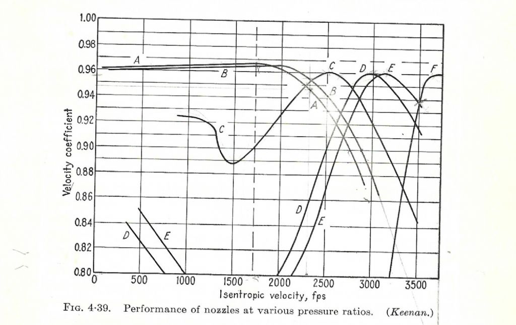
I fully understand the compromises that we must make. I went to the open pocket design of my rotor because I don’t think I can machine blades to the tolerances required for optimum efficiency. I was only partially correct on suggesting a supersonic nozzle for your turbine. The following chart shows the efficiencies of various nozzle designs with changes in pressure. The line marked ‘A’ is a subsonic convergent only nozzle. The line marked ‘B’ is a slightly supersonic with a small divergent section. The lines marked ‘C, D, E, and F’ have progressively longer divergent sections for expansions to larger pressure drops. The dashed vertical line is sonic velocity. You can see from the chart that the subsonic nozzle ‘A’ can be used for pressure ratios well into the supersonic region with efficiencies over 88%. You can also see from the chart that nozzles specifically designed for high pressure drops only operate at maximum efficiency near their design pressures. As you probably have already noticed I get locked into finding the maximum efficiency of each component and sometimes miss the big picture.Thanks Martin and Mark for pointing out that others are using air instead of steam for testing and development. In my case, being able to just push a button and have air at the set pressure immediately available is a big advantage.
Edited By Turbine Guy on 19/05/2019 16:26:46
29 May 2019 at 21:18 #411576Turbine Guy
Participant@turbineguyHello Werner,
I thought about the statement you made about turbulent flow in nozzles causing complete chaos in the turbine housing. The only time I have got chaotic flow from the nozzle when operating on steam is when the boiler has carried over water. When a slug of water is carried over the flow is upset considerably and the turbine speed drops dramatically and will only get up to full speed when most of the liquid is cleared. I have to run water levels way below what is recommended by my boiler manufacturer to keep from getting water carried over when operating with maximum burner heat. Since the pressure you are using is higher than what I use and the boiler on your train is moving, I assume it would be even more difficult to keep water from carrying over.
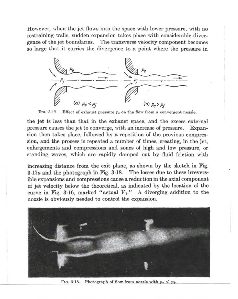
The only other reason for chaotic flow I found is explained below. This was copied from one of my turbine books.
30 May 2019 at 19:30 #411756Turbine Guy
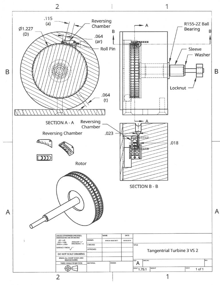
Participant@turbineguyI revised my velocity staged turbine design from what was shown on the post I made 10/04/2019. While I was waiting on my new indexer I tried many combinations of changing the rotor diameter, pocket angle, nozzle angle, and rotor/nozzle position. The following drawing shows what I estimate to be my best combination.
30 May 2019 at 19:37 #4117592 June 2019 at 19:04 #412282Turbine Guy
Participant@turbineguyI added the bores and nozzle hole in my turbine housing as shown in the following photo. We're up to the high summer temperatures, so there is only a few hours in the morning that my non air conditioned shop is comfortable. That's also when I do my yard work, play tennis, and fish so my machining is going relatively slowly. The nozzle hole is not in the correct position. I made a error in the machining and will need to try again. I can still use the housing and just add the nozzle in a different location. The turbine will have an unused hole but it shouldn't effect the performance if I get the next nozzle hole right. I must have the nozzle hole in the correct position to get any meaningful results.
3 June 2019 at 23:52 #412475Werner Jeggli
Participant@wernerjeggli14222Hello Turbine Guy,
Your turbine parts look beautiful, are supported by theory and are also well machined. I really hope it will pan out in the end.
I just returned from a G1MRA event in Toulon/France where I ran the PRR-S2 with 5 coaches for half an hour and everybody clapped their hands. I took along my multipurpose model steam turbine project and discussed it with anybody showing their interest (quite a few).
My ambition is to create versatile steam turbine, which could be used for generating purposes using two 0.8mm nozzles, mounted either at the top or the bottom of the turbine casing for turbo generator application. By using the second slot for a reverse nozzle, working the forward blades from the wrong side (awful engineering – but it works at the price of awful efficiency) it can also be used for a direct mechanical drive.
I'm quite confident that I can reach the peak 10 Watt shaft power target and will run the corresponding tests to prove it.
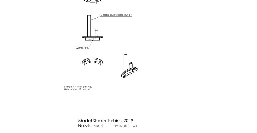
Below is a bad picture of nozzle inset drawing and a Toulon picture. Behind the flower you see the PRR-S2.
 4 June 2019 at 20:21 #412633
Turbine Guy
Participant@turbineguyHello Werner,
Thanks for the kind remarks, my model turbines are intended to be easy to machine but functional. I’m attempting to see if the methods I have used for full size turbines can be used for models. I’m also trying to find ways to get reasonable efficiencies with designs that don’t require extremely thin blades or costly special tools. An example I gave in my 18/04/2019 post showed what Dr. Balje’s guidelines suggest for an axial impulse turbine with the mass flow, available energy, rotor diameter, and speed of my last turbine test with my airbrush compressor. As you have demonstrated, machining the impulse blades is possible but far from easy. The end mill diameter required for this example is 0.013 in. (.33mm). Surprisingly, this diameter is available from McMaster-Carr as shown below. I have trouble not breaking the 0.028 in. (0.71mm) diameter drill I use for nozzles, so I doubt I would have anywhere near the skill required to make the recommended blades of the example.Carbide Two Flute End Mill
Square-End, Uncoated, 0.013" Mill Diameter, 0.039" Long Cut
In stock
$31.44 EachUsing the turbine to turn a high speed generator makes a lot of sense. You really need very high speeds to get reasonable efficiencies. Experimental Flash Steam by J. H. Benson and A. A. Raymond described a turbine made by Jim Bamford that had a 3-1/4 in. diameter rotor that produced 0.47 BHP at 60,000 rpm with 9 oz./min water evaporation. This was tested on his water brake that would have required a speed much below the turbine speed so was after the gearing and probably included the pump power loss. The flash boilers require very high pump pressure and his boiler and turbine/gearing fit in a racing boat about 3 ft. long. There wasn’t enough information to calculate the efficiency. The steam engines are often compared by pounds of water per horsepower hour they require. Jim Bamford’s turbine used approximately 72 lb/HP-hr of steam. For comparison two 5 HP simple steam engines a Semple and a Reliable have steam rates of 49 lb/HP-hr and 40 lb/HP-hr respectively. Both used saturated steam.
Your nozzle insert looks very good. It has a smooth transition from the inlet to the throat and appears to have a good admission length.
I am very interested in getting the results from your tests and based on what you have already accomplished think you will meet your goal.5 June 2019 at 21:04 #412821Turbine Guy
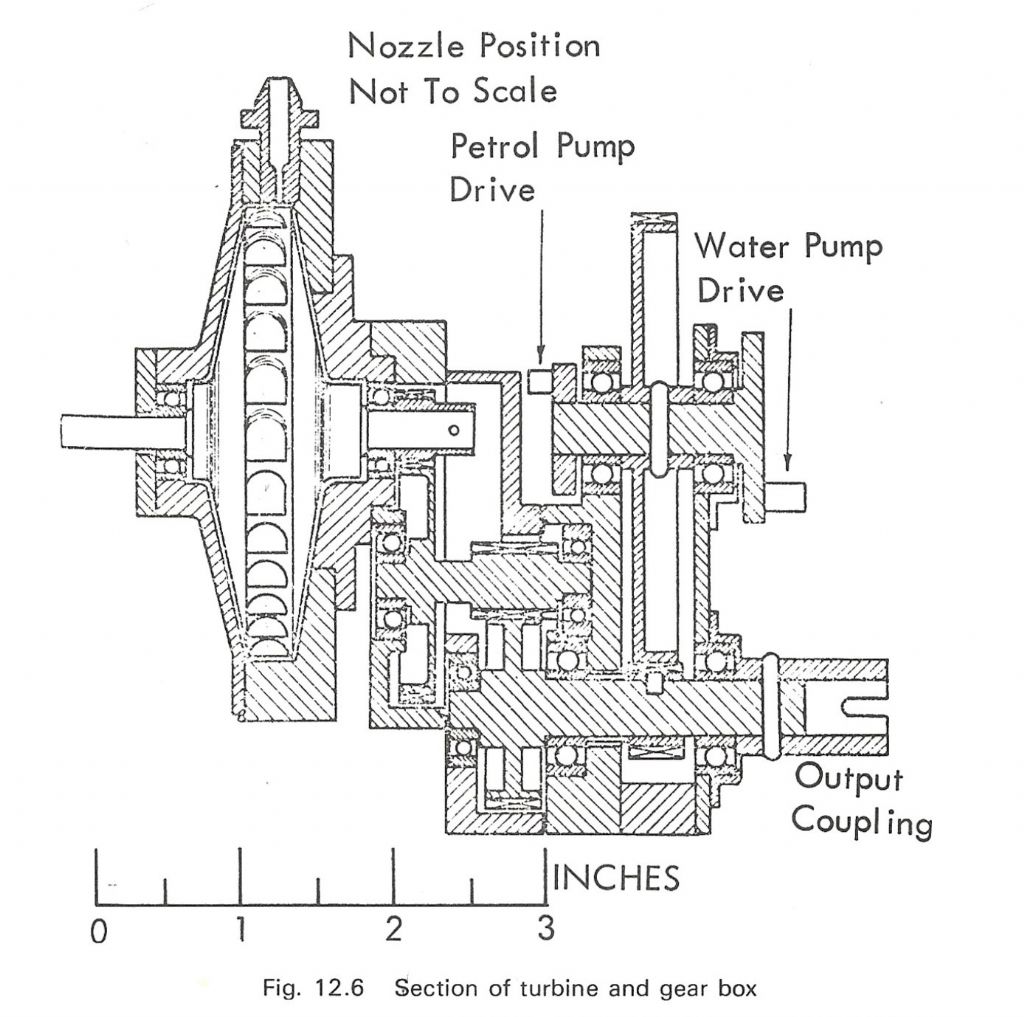
Participant@turbineguyJim Bamford’s turbine described in the last post was a De Lavel axial impulse design. No pictures or drawings of that turbine were shown in the Experimental Flash Steam book. The following drawing of the Stumpf type of tangential impulse turbine that was also designed by Jim Bamford was shown. This turbine has a 3.0 in. diameter rotor and produced approximately 1.2 BHP at 95,000 rpm using 1.5 lb/min of steam. The steam rate for this turbine is 75 lb/HP-hr. Jim apparently realized he needed to run the turbine at the highest speed possible to get the most power. No reason was given for changing to the Stumpf type of turbine from the De Lavel type. Both of these turbines are outstanding in their performance. Since these turbines were used for racing, maximum power was the primary consideration.
Edited By Turbine Guy on 05/06/2019 21:13:07
7 June 2019 at 21:25 #413178Werner Jeggli
Participant@wernerjeggli14222Gentlemen,
Today, I test ran the turbine and with 2 nozzles 0.8mm dia, 3 Bar boiler pressure. I got 41'000 rpm, 22V, 400mA DC output. Now I need also to determine (measure) the other relevant parameters over a 5 minute period like liquid gas consumption, steam temperature, -pressure and -throughput. I would also like to measure the steam temperature prior to entering the nozzles with a thermocouple in direct contact with the steam. However, the steam rushes by very fast, hence its pressure will be substantially lower than the boiler pressure. Does this make the steam more saturated (because of the lower pressure) and how can I take this into account?
The exhaust steam will be condensed in a water cooled spiral tube and then the condensate measured.
Any suggestions ?
8 June 2019 at 01:25 #413194Turbine Guy
Participant@turbineguyHi Werner,
I look forward to seeing all your data. I have a few questions about the information you have already given.
Is the 3 bar gage pressure (pressure above atmospheric)?
Is one of your two nozzles being used for reverse rotation or are both being used for the forward rotation?
Do you know the approximate efficiency of the generator and rectifier?
Is the generator turning the same speed as the turbine?For saturated steam the temperature will be the saturation temperature of the pressure where the measurement is being taken. If you can read the pressure very close to the nozzle, you can get the saturation temperature for that pressure. The percent of moisture will increase as the pressure decreases. If you start with saturated steam at 3.5 bar gage pressure and expand it to atmospheric pressure (0 gage pressure) the moisture in the steam will increase to about 8%. The temperature of the steam at the 3.5 bar pressure is 148 C and at 0.0 bar is 100 C. This is for isentropic expansion.
Since you already got a power output of 8.8 watts from the generator/rectifier, you may have already achieved your goal of 10 watts for the turbine power.
11 June 2019 at 21:25 #413790Turbine Guy
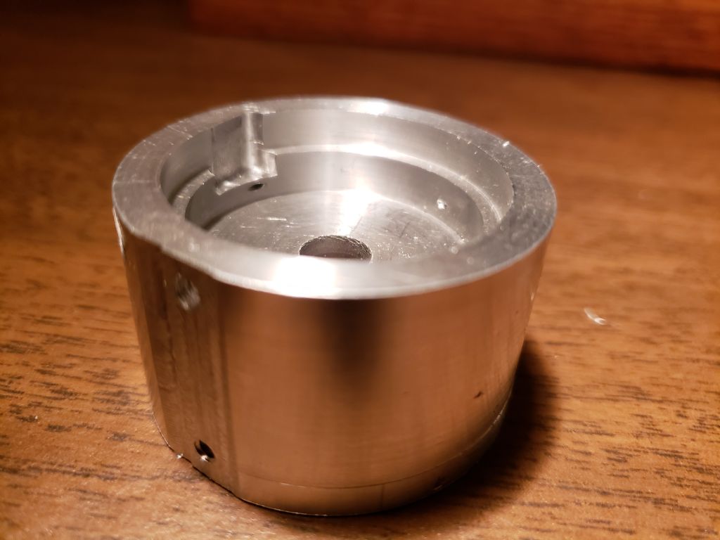
Participant@turbineguyI finished most of the machining on my new turbine housing as shown in the picture below. I only need to add a tube to the nozzle opening and drill two holes in a mounting plate to run the turbine. I designed this turbine to be able to run the first row of blades only by leaving the reversing chamber off. The air or steam can exit the first row of blades out the opening required for the reversing chamber. I want to do this so that I can see the performance of the rotor with the larger diameter and greater number of pockets. The testing I have done on the last turbine indicates the open pocket design has about the same performance of a Terry turbine with the same rotor diameter, number of blades, nozzle admission length, and available energy. My first rotor with 24 pockets appeared to match the performance given by Dr. Balje’s diagram for Terry turbines with around 25 blades. My second rotor with 48 blades also matched the performance for Terry turbines with approximately 45 blades shown in the diagram in the post of 14/03/2019. The new turbine rotor with 60 pockets has more pockets than the curves for the Terry turbine in that diagram. Since the number of blades or pockets has a very large effect on the efficiency, I expect my new turbine running with just one row of blades to exceed the performance given for the Terry turbines in the diagram of the 14/03/2019 post. Whatever happens, I want to see the performance with or without the velocity staging.
12 June 2019 at 07:18 #413819Mike Tilby
Participant@miketilby23489Hi, can I chip in on this very interesting thread which has some impressive photos.
In regard to the design of nozzles. Although, as has been said already, convergent-divergent nozzles are theoretically required to get maximum velocity from steam expanding to below the critical pressure, there were two reports in Model Engineer where people had assessed steam velocity using an impulse plate where the jet was directed against a plate attached to electronic weighing scales. The first report was by Mr Southworth in relation to designing the turbine for his 5" g loco "Turbo" (Southworth (2000) M.E. 185 (4136): 638 – 640). He experimented with many different shapes of nozzle and concluded that the best result was with a plain convergent nozzle which out-performed convergent-divergent nozzles of various angles and lengths – all with the same throat diameter. His article prompted a letter from Tom Jones and Professor Bill Hall (Jones & Hall (2001) Model Engineer 186 (4138): 65). They reported coming to exactly the same conclusion in their own tests on injector nozzles. It seems possible that in miniature nozzles effects such as increased friction in very small diameter ducts make it difficult for the steam to attain supersonic velocities and if sub-sonic steam flows into the divergent part of the nozzle then it will be slowed down instead of accelerated. In both those studies steam from conventional loco boilers was used. However, for their turbines, Mr Bamford and Prof Chaddock used steam at very high pressures and temperatures from flash boilers, so I guess the convergent-divergent nozzles might have worked O.K. under those circumstances. So it seems to me that the question of nozzle design is very much open to doubt and, of course, Werner has had good results with plain nozzles.
Regarding small diameter end mills, I buy them on Ebay where you can often find packs of 10 0.5mm cutters for less than £10.
Regards, Mike
12 June 2019 at 07:39 #413823 Michael GilliganParticipant@michaelgilligan61133Posted by Mike Tilby on 12/06/2019 07:18:48:
In regard to the design of nozzles. Although, as has been said already, convergent-divergent nozzles are theoretically required to get maximum velocity from steam expanding to below the critical pressure, there were two reports in Model Engineer where people had assessed steam velocity using an impulse plate where the jet was directed against a plate attached to electronic weighing scales. The first report was by Mr Southworth in relation to designing the turbine for his 5" g loco "Turbo" (Southworth (2000) M.E. 185 (4136): 638 – 640). He experimented with many different shapes of nozzle and concluded that the best result was with a plain convergent nozzle which out-performed convergent-divergent nozzles of various angles and lengths – all with the same throat diameter. His article prompted a letter from Tom Jones and Professor Bill Hall (Jones & Hall (2001) Model Engineer 186 (4138): 65). They reported coming to exactly the same conclusion in their own tests on injector nozzles. It seems possible that in miniature nozzles effects such as increased friction in very small diameter ducts make it difficult for the steam to attain supersonic velocities and if sub-sonic steam flows into the divergent part of the nozzle then it will be slowed down instead of accelerated. In both those studies steam from conventional loco boilers was used. However, for their turbines, Mr Bamford and Prof Chaddock used steam at very high pressures and temperatures from flash boilers, so I guess the convergent-divergent nozzles might have worked O.K. under those circumstances. So it seems to me that the question of nozzle design is very much open to doubt and, of course, Werner has had good results with plain nozzles.
.
Useful references, Mike

Aphorism : You can't scale nature
MichaelG.
Edited By Michael Gilligan on 12/06/2019 07:41:08
12 June 2019 at 17:16 #413919Turbine Guy
Participant@turbineguyMike Tilby,
Thanks for adding your valuable information on sonic nozzles. The section view of Jim Bamford’s turbine shown in the 05/06/2019 post shows a sonic nozzle. This drawing cautions that the nozzle position is not to scale. I think that caution was added to make clear the section through the nozzle had been rotated relative to the section of the rest of the turbine and the flow from the nozzle would be in the opposite direction relative to the rotor pockets. If he did use a sonic nozzle for this turbine it would definitely make the point that sonic nozzles can be used for pressures much higher than the sonic pressure. I have designed turbines with supersonic converging/diverging nozzles that worked well but the lowest power of these designs was about 8 hp (6 kw). These nozzles also had a straight section after the diverging section to stabilize the flow before it entered the inside of the turbine housings.13 June 2019 at 17:23 #414109Mike Tilby
Participant@miketilby23489Posted by Werner Jeggli on 07/06/2019 21:25:44:Gentlemen,
Today, I test ran the turbine and with 2 nozzles 0.8mm dia, 3 Bar boiler pressure. I got 41'000 rpm, 22V, 400mA DC output. Now I need also to determine (measure) the other relevant parameters over a 5 minute period like liquid gas consumption, steam temperature, -pressure and -throughput. I would also like to measure the steam temperature prior to entering the nozzles with a thermocouple in direct contact with the steam. However, the steam rushes by very fast, hence its pressure will be substantially lower than the boiler pressure. Does this make the steam more saturated (because of the lower pressure) and how can I take this into account?
The exhaust steam will be condensed in a water cooled spiral tube and then the condensate measured.
Any suggestions ?
Hello Werner, I would think that the drop in pressure at the entrance to your nozzles would result from friction along the pipe and from loss of heat by convection from the outside of the pipe. Of course both these effects will depend on diameter and length and nature of the surfaces of the pipe. Drop in pressure will mean a lower saturation temperature and friction will increase the heat content of the steam. So these effects will act to keep the steam dry. However, loss of heat by convection will tend to lower the superheat and/or increase wetness of the steam. It seems to me that the only way to be certain of the steam condition would be to ensure the steam is initially superheated to an extent that it remains superheated when it reaches the thermocouple at the nozzle entrance. If its temperature drops to the saturation temperature you will not know how wet the steam is since its temperature will not decrease further until it has essentially all condensed. I guess the only way to be sure of the pressure at the nozzle entrance is to have a pressure gauge attached at that point and then you will be able to look up the saturation temperature. (On my boiler I have a thermocouple at the entrance to the nozzle and I'm currently making some connections for pressure gauges before and after the first nozzle of the turbine).
No doubt I've over-looked something in the above waffle so I am ready to be corrected.
Mike
-
AuthorPosts
- Please log in to reply to this topic. Registering is free and easy using the links on the menu at the top of this page.
Latest Replies
Home › Forums › Stationary engines › Topics
-
- Topic
- Voices
- Posts
- Last Post
-
-
Injectors
Started by:
pansy123 in: General Questions
- 6
- 7
-
3 July 2025 at 07:05
Dave Wootton
-
Twin Engineering’s heavy mill/drill quill removal
Started by:
Martin of Wick in: Manual machine tools
- 8
- 18
-
3 July 2025 at 06:20
Diogenes
-
Pattern Makers Vice
Started by:
 Vic
in: The Tea Room
- 7
- 9
-
2 July 2025 at 21:51
 KEITH BEAUMONT
-
J&S grinder – belt which way ?
Started by:
gerry madden in: Manual machine tools
- 7
- 9
-
2 July 2025 at 21:44
not done it yet
-
Meddings MF4 Manual
Started by:
Richard Kirkman 1 in: Help and Assistance! (Offered or Wanted)
- 11
- 23
-
2 July 2025 at 21:38
Richard Kirkman 1
-
Haining vertical dairy engine boiler.
Started by:
apprentice in: Beginners questions
- 3
- 7
-
2 July 2025 at 20:52
 JasonB
-
Speed camera
1
2
Started by:
 David George 1
in: The Tea Room
- 20
- 39
-
2 July 2025 at 20:01
Plasma
-
Motor won’t start
Started by:
Rowan Sylvester-Bradley in: Beginners questions
- 9
- 9
-
2 July 2025 at 17:30
larry phelan 1
-
IME Watchmakers lathe
Started by:
Greensands in: Manual machine tools
- 11
- 16
-
1 July 2025 at 21:41
Dave S
-
Request for a Slot to be Milled in a Shaft
Started by:
James Alford in: Help and Assistance! (Offered or Wanted)
- 9
- 18
-
1 July 2025 at 21:03
bernard towers
-
Bearing boxes for ball race
Started by:
Paul McDonough in: Beginners questions
- 9
- 17
-
1 July 2025 at 21:02
Paul McDonough
-
The Stevenson Trophy – Entries Invited
Started by:
 Neil Wyatt
in: Website Announcements
- 1
- 2
-
1 July 2025 at 18:44
 Neil Wyatt
-
The Bradford Cup – Nominations Wanted
Started by:
 Neil Wyatt
in: Website Announcements
- 1
- 2
-
1 July 2025 at 18:41
 Neil Wyatt
-
FreeCAD v1.0 tutorials
1
2
3
Started by:
 Michael Gilligan
in: CAD – Technical drawing & design
- 12
- 54
-
1 July 2025 at 18:31
Speedy Builder5
-
All things Beaver Mill
1
2
…
8
9
Started by:
Robert James 3 in: Manual machine tools
- 43
- 208
-
1 July 2025 at 18:22
Charles Lamont
-
Dial test indicator vs Dial indicator
Started by:
martian in: Workshop Tools and Tooling
- 17
- 24
-
1 July 2025 at 16:59
Clive Foster
-
Help for DIY lathe build.
1
2
Started by:
moogie in: Help and Assistance! (Offered or Wanted)
- 16
- 32
-
1 July 2025 at 15:21
David Senior
-
Firth Valve Gear
Started by:
Andy Stopford in: Traction engines
- 9
- 18
-
1 July 2025 at 12:59
Nigel Graham 2
-
M type top slide conversion??
Started by:
jimmyjaffa in: Beginners questions
- 7
- 11
-
1 July 2025 at 11:35
 David George 1
-
Offen screw type telescopic gauge.
Started by:
Graeme Seed in: Workshop Tools and Tooling
- 4
- 9
-
1 July 2025 at 10:41
Graeme Seed
-
2 Machine lights
Started by:
modeng2000 in: Workshop Tools and Tooling
- 2
- 6
-
1 July 2025 at 08:57
Dalboy
-
New member looking for help
Started by:
 manfromthemist
in: Introduce Yourself – New members start here!
- 11
- 24
-
1 July 2025 at 08:19
Juddy
-
Wiring up a single phase AC motor with 4 wires
Started by:
ell81 in: Beginners questions
- 6
- 8
-
30 June 2025 at 19:49
Howard Lewis
-
New (old!) member
Started by:
iansoady in: Introduce Yourself – New members start here!
- 3
- 3
-
30 June 2025 at 19:30
Howard Lewis
-
Boiler Design – issue 4765
1
2
…
7
8
Started by:
Charles Lamont in: Model Engineer & Workshop
- 26
- 178
-
30 June 2025 at 12:58
Paul Kemp
-
Injectors
-


 . The good performance I reached more or less by trial and error. I'd love to get them supported by a more scientific approach. The problem is the turbulent steam flow in the turbine. I do not think to being able to build a more efficient multistage turbine, reducing the pressure drop to the required 0.8 Bar/stage, which would insure laminary steam flow.