Model Turbines
Model Turbines
Home › Forums › Stationary engines › Model Turbines
- This topic has 606 replies, 28 voices, and was last updated 12 July 2025 at 16:28 by
Turbine Guy.
-
AuthorPosts
-
29 November 2024 at 19:01 #767528
Turbine Guy
Participant@turbineguyI compared the tilting of the rotor shaft of Tangential Turbine 5B and Axial Turbine 4C by moving the propeller end of each perpendicular to the axis of the ball bearings. Tangential Turbine 5B had almost no movement and Axial Turbine 4C had about the same movement even with the extra ball bearing. Since both turbines have the same very close sliding fit between the ball bearing bore and the rotor shaft, the extra play of Axial Turbine 4C is primarily due to the extra clearance between the ball bearing OD and the housing bore. When I made Axial Turbine 4 I found that the fit between the ball bearing OD and the housing bore was a little loose but I thought it was tight enough to work. When I made Tangential Turbine 5 I used a reamer for the housing bore that was 0.0005 smaller and got a tighter fit. I decided to try filling the clearance of Axial Turbine 4 between the ball bearings OD and the housing bore with Loctite 290. Because Loctite 290 is designed to flow into very tight spaces and tends to get into spaces where it is not desired, I didn’t apply it to the ball bearing ODs for fear it would get inside the ball bearings and lock them up. Instead I applied it to the housing bore and waited until it got a little tacky and then installed the ball bearings in the housing. I waited a couple hours for the Loctite to partially cure and tried tilting the rotor. The tilt is almost entirely gone and the rotor rotates freely and will spin a few seconds after spinning it by hand. I will wait 24 hours until it is fully cured and then run a test to see if this improves the performance.
30 November 2024 at 21:02 #767795Turbine Guy
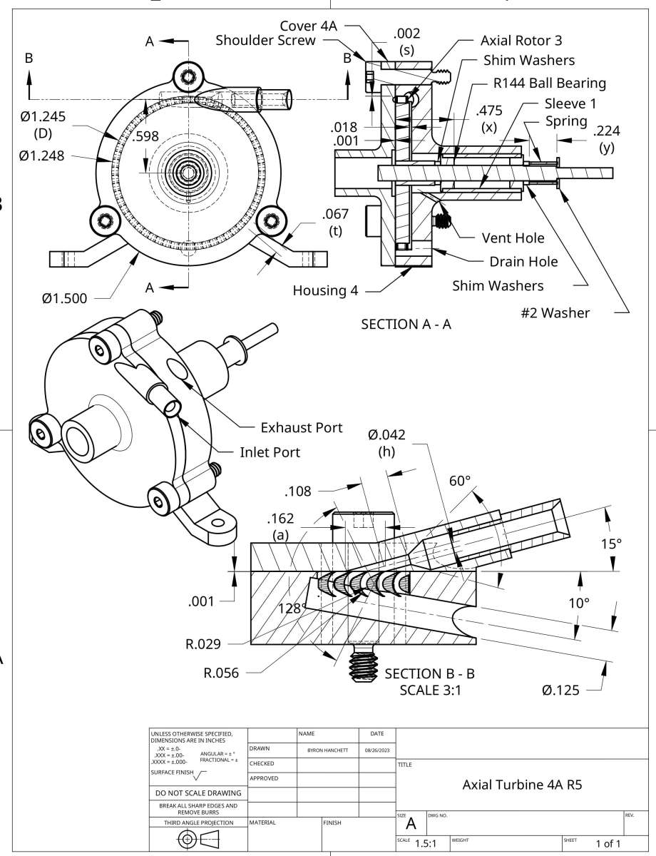
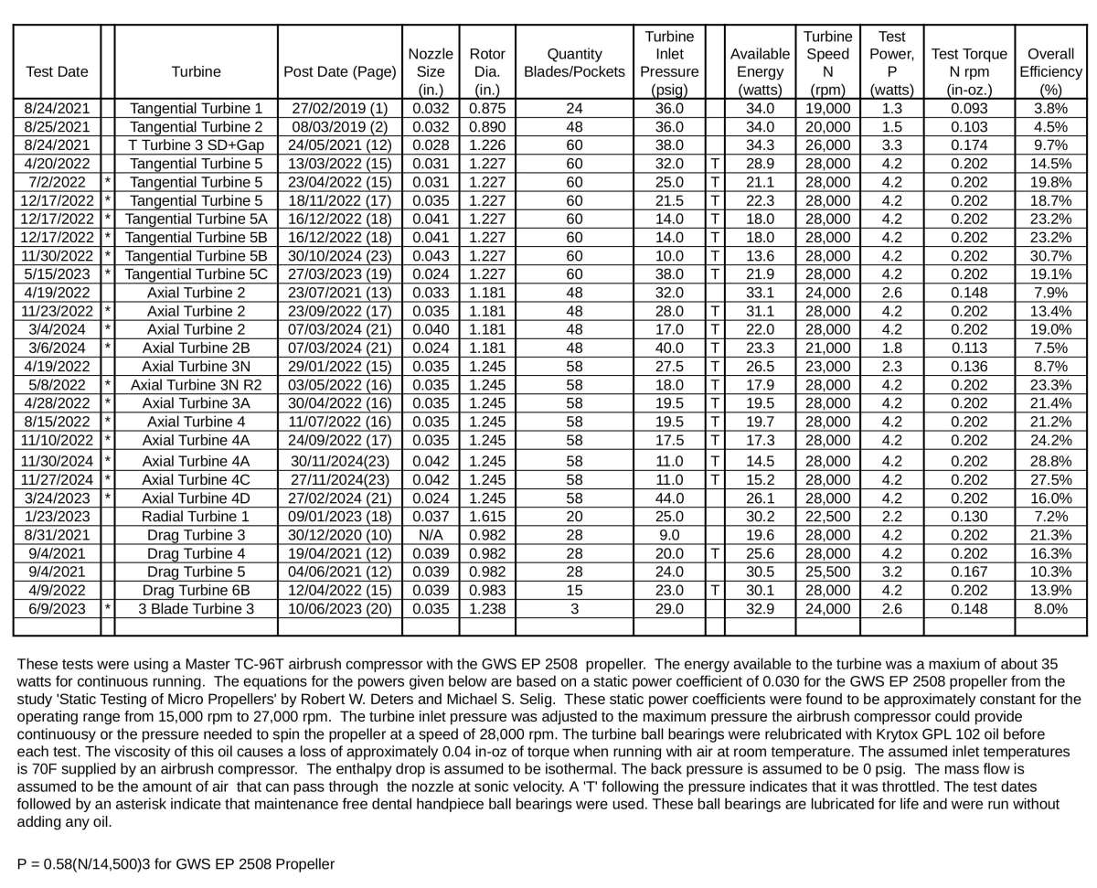
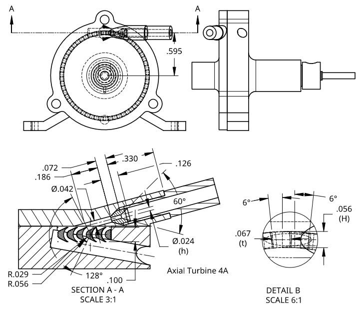
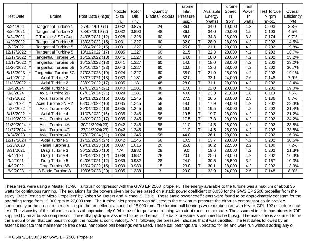
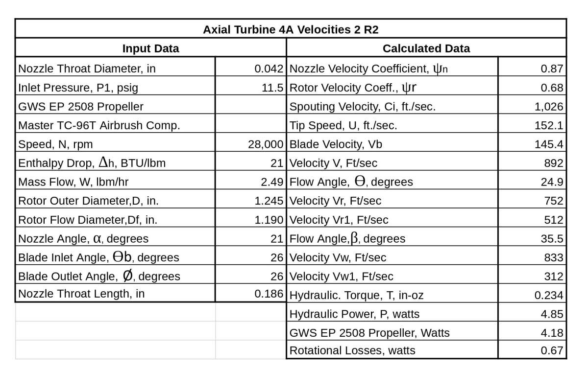
Participant@turbineguyThe dental ball bearings of Axial Turbine 4A shown on the following drawing were Loctited with the rotor in the same position as the last test of Axial Turbine 4C so the performance could be compared with everything the same except for the extra bearing. The air pressure required to run Axial Turbine 4A at 28,000 rpm was 11 psig as shown by the 11/30/2024 test in the following spreadsheet. Eliminating the tilting of the rotor shaft due to excess clearance on the OD of the ball bearings improved the efficiency of Axial Turbine 4A to 28.8% compared with the efficiency of 27.3% before the Loctite was tried. This showed that with the proper bearing clearances, or the bearings fixed to the housing with Loctite, the efficiency of Axial Turbine 4A with two ball bearings is better than Axial Turbine 4C with three ball bearings.

 5 December 2024 at 14:08 #768756
Turbine Guy
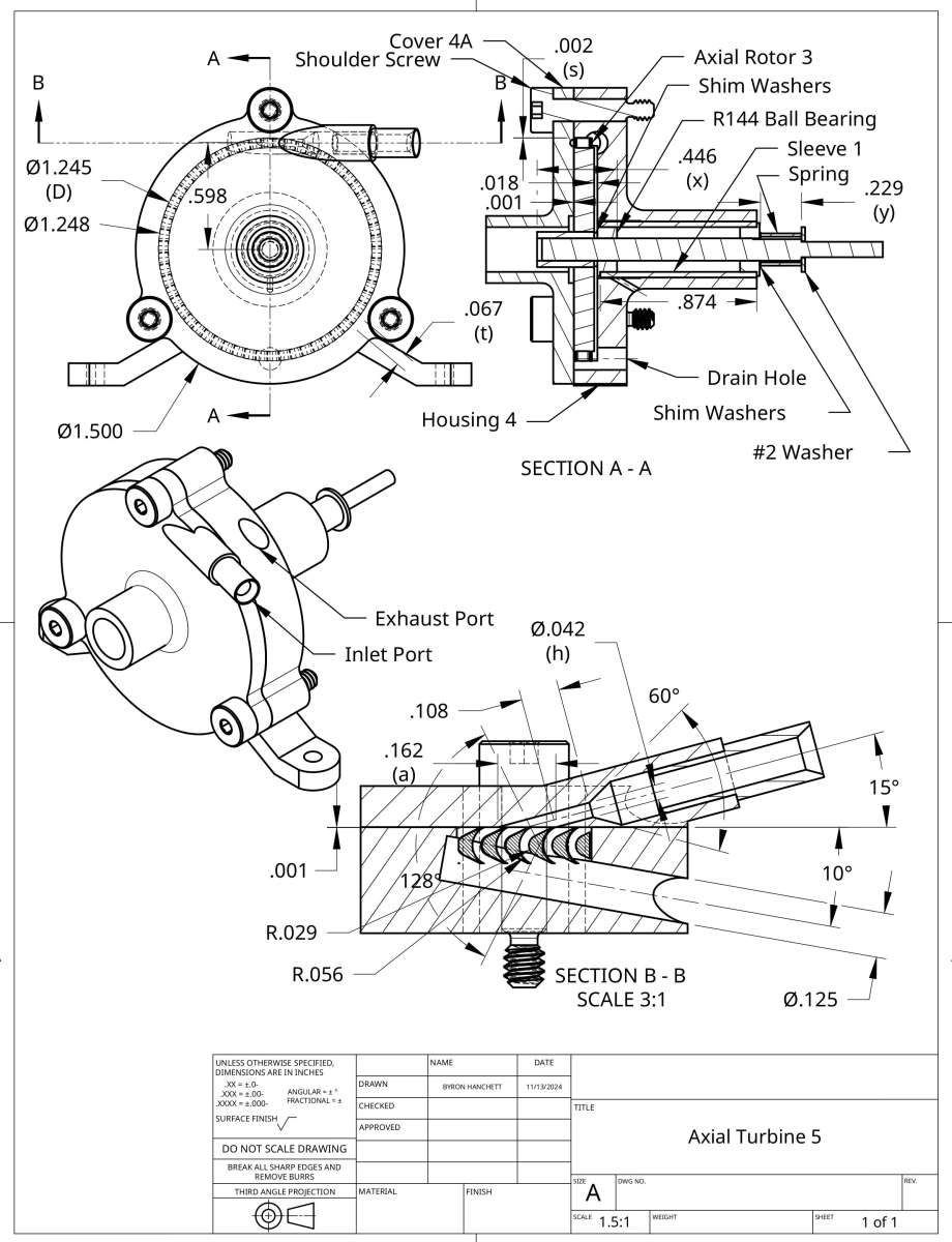
Participant@turbineguyThe rotor in Axial Turbine 4 was designed for the housing used by Axial Turbine 3 that required the sleeve in the rotor to project out toward the inner ball bearing. This creates quite a bit of cantilever that I eliminated in the design of Tangential Turbine 5. I am going to try pushing the sleeve in the rotor of Axial Turbine 4 so that it projects out the other side as shown in the following drawing. I am also going to put a longer sleeve in the housing bore that will get the face of the inner ball bearing closer to the face of the rotor as also shown on the following drawing. Since these changes are significant, I will call this Axial Turbine 5. I also show below the last revision of Axial Turbine 4A for comparison. Reducing the amount of cantilever should reduce the deflection and the load on the ball bearings and increase the efficiency.

 7 December 2024 at 16:47 #769280
Turbine Guy
Participant@turbineguyI finished the machining on Axial Turbine 5 and got a very good fit between the ball bearing OD and the sleeve bore. This eliminated almost all tilting of the rotor. The temperature is below freezing in our area and my shop is uninsulated and the temperature is 46 F. My first test at this temperature almost matched the performance of Axial Turbine 4A with the ball bearings OD Loctited to the sleeve bore. With my electric space heater It would take about 4 hours to heat my shop up to the 70 F temperature that all the tests in the spreadsheet shown in the 30 November 2024 post were run at. Because it takes a lot of time to heat my shop and increases our electric bill significantly, I prefer to do the final setup and testing in warmer weather. The reason the temperature is important in the test results is the efficiency of the turbine drops significantly at low temperatures. A test I ran a while ago started with a shop temperature at 50 F. I tested the turbine at that temperature and then again at 70 F. There was an increase in performance of about 9.5% running at the higher temperature. The first test of Axial Turbine 5 looks promising, I will find the optimum settings and run a test at 70 F when the weather gets warmer.
13 December 2024 at 19:44 #770166Turbine Guy
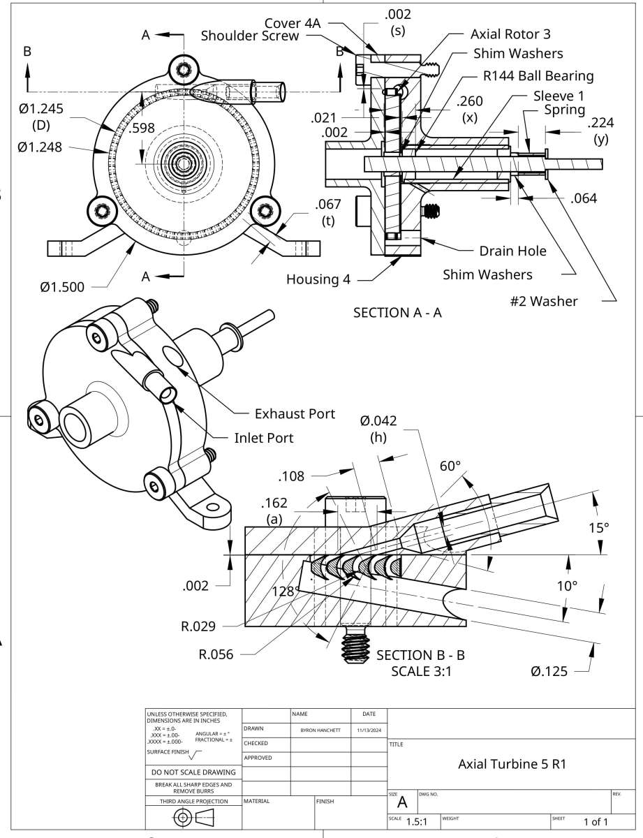
Participant@turbineguyIt got warm enough in our area for me to test Axial Turbine 5 at 70F after finding the optimum position of the rotor. I was not able to match the last performance of Axial Turbine 4A even though I felt I had made significant improvements. I checked everything I changed and could not find anything I had done wrong. I knew the rotor for Axial Turbine 5 had a very slight imbalance causing a little vibration at high speeds but could not balance it by Werner Jeggli’s method shown in the 29 November 2020 post on page 9 because the diameter was not the same on each side of the rotor. I decided to make a revision to Axial Turbine 5 that has the diameter the same size on both sides of the rotor as shown on the following drawing. I then balanced the rotor and ran a test of Axial Turbine 5 R1 and it did significantly worse than before the change. After checking everything I could think of and not finding a reason the performance kept getting worse, I tried the propeller used on the last test of Tangential Turbine 5B and the performance increased quite a bit. I compared the two propellers and the one I first used on Axial Turbine 5 R1 appeared to have more pitch on one blade like it had been twisted from the original position. I was curious how easy it would be to twist the blades into a new position so I tried twisting slightly by hand the blades on the second propeller I used on Axial Turbine 5 R1. It did not take much force to twist them slightly from the original position. I turned both blades in the direction that reduced the pitch by about the same slight amount and then installed the propeller on Axial Turbine 5 R1 and ran a test. With the pitch reduced slightly, Axial Turbine 5 R1 exceeded the best performance of all my turbines even though the test was at 52 F. This showed how much the test results could change if the propeller blades get twisted from their original position and how little force it takes to twist them. The test results with the GWS EP 2508 propeller have been very consistent up to the tests of Axial Turbine 5 so I looked for what could have twisted the blades on this turbine. The only thing I could think of was that the press fit of the propeller on the rotor shaft was larger than I have had before and required extra force to push the propeller onto the shaft. Apparently I was not as careful as I needed to be in removing and reinstalling the propeller several times while finding its optimum position. I ordered some new propellers and will try to be more careful in the amount of force I use and how I push the propeller onto the shaft.
 17 December 2024 at 20:30 #770752
Turbine Guy
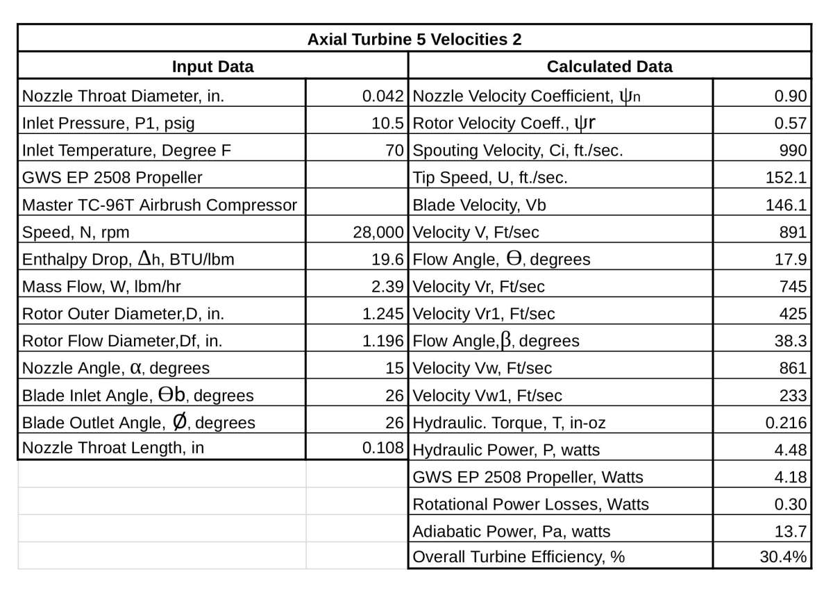
Participant@turbineguyI received the new GWS EP2508 propellers and carefully installed one on Axial Turbine 5. I warmed my shop up to 70 F and ran a test and added the results to the following spreadsheet. The results were as I expected due to the reduction in the amount of cantilever that should have resulted in a slight increase in efficiency. Axial Turbine 5 performed slightly better than any of the Axial Turbine 4 configurations. There was no detectable vibration at the top speed of 28,000 rpm, so the balancing of the rotor was successful. This also helped raise the efficiency.
 19 December 2024 at 15:55 #771062
Turbine Guy
Participant@turbineguyI explained the method I used to find the rotor velocity coefficient (RVC) by turning a large propeller at a very low speed in the second 23 March 2023 post on page 19. I like this method better than calculating the RVC from the maximum stall torque that was explained in the first 23 March 2023 post because it gives the effective RVC directly instead of estimating it from the maximum RVC. In my latest spreadsheet for estimating the RVC from testing with a propeller at low speeds I added the option of using propeller power coefficients since that is the most accurate when using APC propellers for small power outputs. Their power is given in horsepower shown in three decimal places so it rounds to about 0.001 Hp at the low power levels of my tests. Their torques are given in in-lbs and shown in three decimal places so that is a little better but using the power coefficients gets the most accurate result. The following spreadsheet shows the results for the last test of Axial Turbine 5. I chose the APC 5 x 3EP propeller since it is the largest propeller that is in its normal operating range at the speeds shown in the following spreadsheet that was copied from the Static Testing of Micro Propellers by Robert W. Deters and Michael S. Seleg. Since the rotational losses are proportional to the speed cubed, the losses at the 4,300 rpm test speed would be a very small percent of the losses at the top speed of 28,000 rpm (4.300/28.000)^3 = 0.0036).

 19 December 2024 at 18:36 #771130
Turbine Guy
Participant@turbineguyThe reason I updated the rotor velocity coefficient (RVC) in the last post was because I have been trying to find why the rotational losses for the turbines that use the axial flow rotors were so much higher than for the tangential flow rotors. The blades on the axial rotors raise the losses over the pockets of the tangential rotors but are quite a bit larger than the estimates given by most sources I have found. The RVC found in the last post is what I used in the following spreadsheet to find the rotational losses. These rotational losses are within the estimations of the sources I have found. The rotational losses found in this spreadsheet are still a little higher than the estimates of some of the sources but less than others. None of the sources include the effect of moisture on the rotational losses for air but the sources showing the rotational losses for steam indicate it is significant. When I run my tests with air at 70 F that I use for spreadsheets, the moisture in the air increases due to the expansion of the air in the nozzle so might account for the rotational losses being on the high side.
 15 February 2025 at 19:54 #783429
Turbine Guy
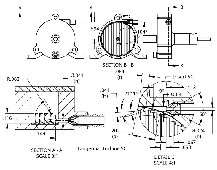
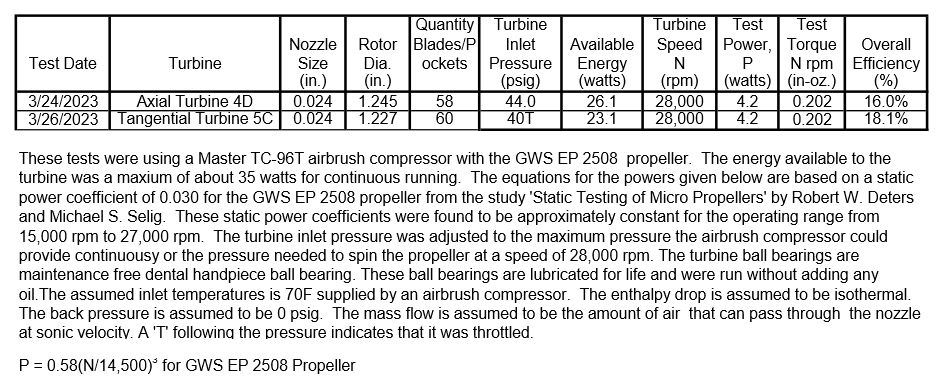
Participant@turbineguyThe following test sheet shows the performance of Axial Turbine 4D and Tangential Turbine 5C running on air I said I was going to show after the 27/03/2023 post that also included the following drawings. I will look at the reasons for this performance in the next posts.
I took a second look at the way the nozzle velocity coefficients were found
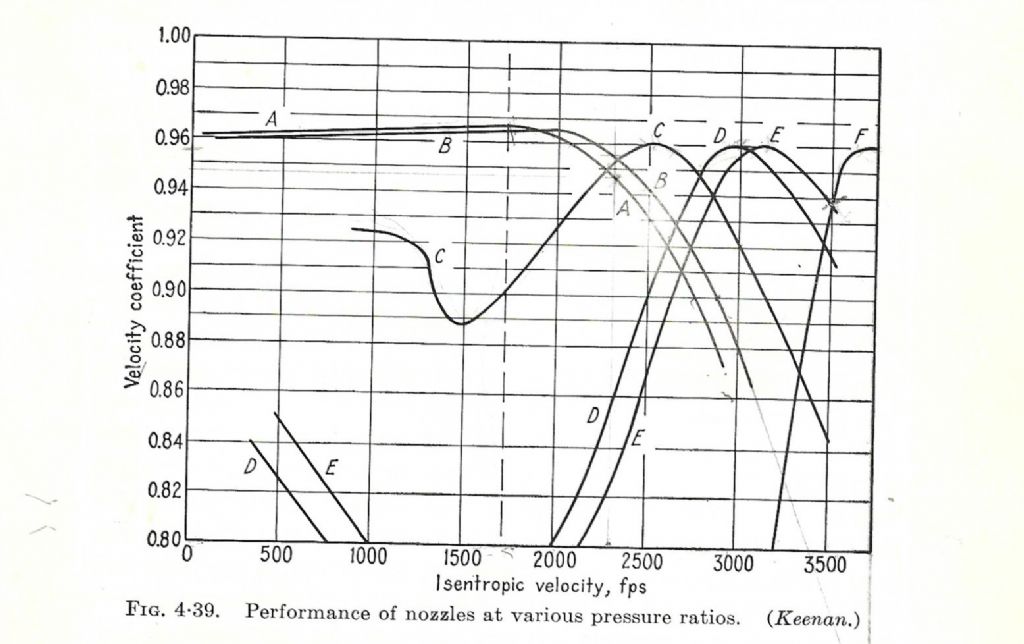
I estimated the nozzle velocity coefficient of Axial Turbine 4D to be approximately 0.69 and 0.73 for Tangential Turbine 5C for the tests shown in the last post. These velocity coefficients were determined by starting with the velocity coefficient of 0.93 for the conical nozzle as explained in the 17/03/2023 post then finding the reduction for the pressure drop due to friction. The reduction due to pressure drop was 0.94 for both turbines since they had the same nozzle throat length. This reduced the nozzle velocity coefficient to 0.87. I then found the reduction for expanding to supersonic velocities with a converging only nozzle shown in the following diagram as line A. In the tests shown in the previous post, the Mach number for Axial Turbine 4D was 1.47 and for Tangential Turbine 5C was 1.43. The reduction for expanding supersonic is approximately 0.97 for both turbines when rounded to two decimal places. This reduces the nozzle velocity coefficient to 0.84 for both turbines. The last reduction was for the distance between the nozzle outlet to the rotor. This was 0.186” for Axial Turbine 4D and 0.113” for Tangential Turbine 5C as shown on the two drawings of the last post. The reduction in nozzle velocity coefficient for this was 0.82 for Axial Turbine 4D and 0.87 for Tangential Turbine 5C. This reduced the nozzle velocity coefficient to 0.69 for Axial Turbine 4D and to .73 for Tangential Turbine 5C as stated at the first of this post. The reduction in rotor velocity coefficient for supersonic velocity was 0.98 for both turbines. The rotor velocity coefficient found from the static torque test explained in the 23/03/2023 post were 0.68 for Axial Turbine 4A and 0.27 for Tangential Turbine 5B. Neither of these turbines had the insert and the discharge velocity of the nozzles were approximately sonic, so using the correction for supersonic velocities reduces the rotor velocity coefficient to 0.67 for Axial Turbine 4D and to 0.26 for Tangential Turbine 5C. I will show in the next post how the test results in the last post compare with the velocity diagrams like shown in the 23/03/2023 post.
Edited By Turbine Guy on 29/03/2023 21:20:09I looked at the way I determined the nozzle velocity coefficients in this post and believe the corrections I made for the distance from the nozzle outlet to the rotor are not correct. I believe the methods used for the other corrections are valid and the corrected value for the nozzle velocity coefficient of 0.84 for both turbines should be used. The distance from the nozzle outlet to the rotor is space needed for the gas to expand to supersonic Velocities. I will try to find the distance required for the gas to expand to supersonic velocities and the effect of having too short or too long of a distance.
I tried adding an insert with a throat diameter of 0.025” in the nozzle of Axial Turbine 5 to see if the improvements I made changing from Axial Turbine 4 to Axial Turbine 5 would increase the efficiency using the insert. The views shown in the post I quoted show approximately the dimensions of the insert I added in Axial Turbine 5 and how it fits in the nozzle since the nozzle was the same for both Axial Turbine 4 and Axial Turbine 5. Instead of the performance improving, the maximum speed of the propeller for the pressure of 44.0 psig shown for Axial Turbine 4D in the table decreased from 28,000 rpm to 22,000 rpm. This was a substantial decrease in performance so I tried a test running on steam and got similar results. I removed the insert and had the same performance running on air as shown in the table of the 17 December 2024 post so there wasn’t a problem with any of the parts or the placement of the rotor in the housing. The only reason I could find for this drop in performance using the insert was the air not expanding to supersonic velocity. I estimated the performance with sonic velocity and it was still much higher than found in the test. The last thing I could think of was to estimate the performance based on the velocity that would pass the mass flow at the discharge diameter of 0.042”. In other words, expanding to a lower velocity instead of to a supersonic velocity. The estimated performance based on expanding to a lower velocity was close to what was found in the test so this appears to be what happened. I have got performance with the inserts that could only be obtained with the flow expanding to supersonic velocities like shown in the quoted post so I am not sure why I only had this problem with this last configuration. When I remove an insert, I have to remove all the Loctite that held it in place. When I did the cleanup after removing the insert used in this last test, I noticed that I had to remove more Loctite than normal. If the flow had to pass through this extra Loctite it might have been what caused the flow to go subsonic. If you use Loctite 290 to hold a nozzle or insert in place you must be very careful not to let the clearance get too large or it can block part of the flow. Loctite 290 is designed to work in very tight clearances. When I have kept the clearances small Loctite 290 has worked very well for me running with air or steam.
13 March 2025 at 17:25 #788574Turbine Guy
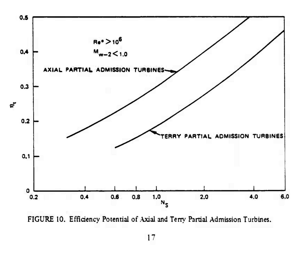
Participant@turbineguyI was looking for tests of Terry Turbines and found the Design Study for a 100 Watt Turboalternator Power Unit by O. E. Balje and R. Spies at This Link. The study showed designs for Terry Turbines in the size range of my models. There was a lot of discussion about bearings which you might find interesting. They found that even at the 100 watt power level the choice of ball bearings was very important. Adding the self lubricating dental ball bearings to my model turbines improved the performance substantially. This is especially important at the low power levels since the rotational losses become a higher percentage of the total losses. I have stated before that I believe the overlapping pockets of my tangential turbines is more efficient than the blades of a Terry Turbine in the very small size of my models. This is due to the difficulty of making the blades and holding the necessary clearances. The following chart is a copy of Figure 10 from this report that shows the estimated efficiency of Terry Turbines based on what they found from actual tests. The specific speed, Ns, for Tangential Turbine 5B for the 11/30/2022 test shown in the table in the 17 December 2024 post is 2.0. From Figure 10, the efficiency of the Terry Turbine for Ns = 2.0 is approximately 27%. The actual efficiency of Tangential Turbine 5B was 30.7% in the 11/30/2022 test so it exceeded the estimated efficiency of a Terry Turbine for the same Ns = 2.0.
Table 6 from the report shows the performance of a 1.217” OD Terry Turbine approximately the same size as the 1.227” OD Tangential Turbine 5B is shown below. This test was run on Nitrogen at much higher pressure and expanded to very low temperatures which increased the density resulting in a much higher mass flow than I had in my tests. The Terry Turbine required a specific speed Ns of 2.78 to reach approximately the same efficiency as Tangential Turbine 5B got with a Ns of 2.0. This also illustrates that the overlapping pockets are just as effective as blades in the Terry Turbine in very small turbines. This is probably due to the compromises that have to be made in the machining of the Terry rotors.
I will show in the next posts why the amount of information required to calculate the specific speed, Ns, is enough to make a much better estimate of the performance compared with just the ratio of the spouting velocity to the rotor tip velocity.


 15 March 2025 at 14:44 #788864
Turbine Guy
Participant@turbineguyI said I would show why the amount of information required to calculate the specific speed, Ns, is enough to make a much better estimate of the performance compared with just the ratio of the spouting velocity to the rotor tip velocity in the last post.
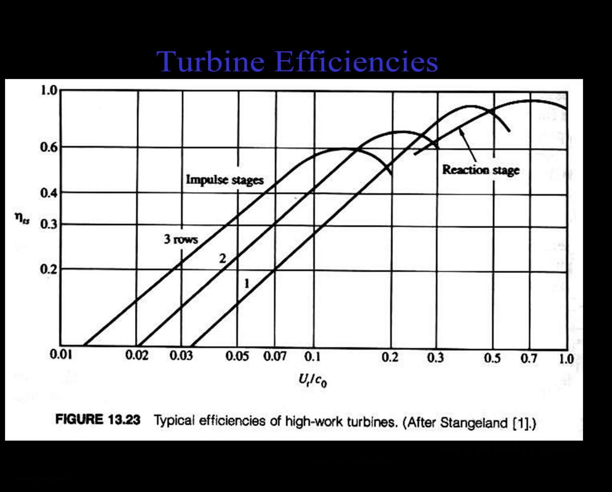
The line marked axial partial admission turbines of Figure 10 shown in the last post is for axial turbines with Reynolds number, Re, greater than 10^6 and nozzle outlet velocities with Mach number, M, sonic or below. This line shows the potential of axial turbines with large numbers of blades and large numbers of nozzles and can be compared to the efficiencies shown in the following chart for rotor tip speed, U, to spouting velocities, Co, ratios. That line was shown to illustrate the potential of axial turbines under ideal circumstances. The report states that the requirements that need to be met to get efficiencies this high cannot be met with very small turbines and the Terry Turbines have better efficiencies with supersonic velocities in very small sizes. That was why they chose the Terry Turbines for the size of the turbines required. Dr. Balje has stated in other reports that the performance of Terry Turbines is about the same as axial turbines when the amount of blades is very small. This is what I have found from my testing. Axial Turbine 5 is my best axial turbine and has almost identical efficiency as Tangential Turbine 5B with subsonic velocities as shown in the following chart.
The efficiency of the 1.217” Terry Turbine shown in Table 6 of the last post was 29.9% for a specific speed Ns = 2.78. The efficiency shown for a Terry Turbine with this specific speed was about 34% from Figure 10 shown in the last post. The 1.217” Terry Turbine did not reach the maximum efficiency due to the high Mach number of 3.42 shown in Table 6 since Figure 10 was based on sonic or below spouting velocities as shown. This example shows the reduction in efficiency of running with highly supersonic velocities in the very small turbines. The example used a proper converging/diverging nozzle with round entry into the throat. The very small throat and exit diameters of the tiny nozzles result in higher losses due to friction.
 15 March 2025 at 17:33 #788889
Mike Tilby
Participant@miketilby23489Hi Byron
I found the reference by Balje & Spies to which you provided the link in your post on 13th Mar, to be very interesting. The vibration issue with plain bearings is a factor (another factor) of which I was not aware.
I found the introduction to the following article gives a helpful explanation of the causes of the instability although the article soon gets far too mathematical for me to follow.
It also discusses specially shaped bearings such as pressure dam bearings that increase the speed before instabilities arise. But they seem too complicated to reproduce in miniature.
Anyway, the article you cited is making me have second thoughts about using plain graphite bearings in the turbine that I am attempting to build. As you know, I was going to use ball bearings made for dental handpieces which are rated for very high speeds and can run with water as lubricant or no lubrication at all. These are hybrid bearings i.e. ceramic balls in stainless steel races. I had decided to use those bearings and bought some but then I decided to supply the turbine with superheated steam at 200 – 300 degC. However, the bearings have nylon cages and that severely limits their working temperature. Hence the switch to water-lubricated graphite bearings.
After reading the paper you cited I searched on-line to see if other types of dental bearings were available and found some hybrid dental bearings have cages made from PEEK or PAEK. These materials have temperature limits of 250 and 300 degC but I don’t know the limits for the actual bearings. I have sent queries to the companies but I fear there will be problems buying small quantities from the big companies at sensible prices.
Mike
16 March 2025 at 18:33 #789078Turbine Guy
Participant@turbineguyI mentioned in the 29 July 2024 post that the steam stayed superheated all the way through the turbine in the test described in that post. I found the mass flow out of the boiler to be 1.4 lb/hr by the 11 minute time required to boil out ½ cup of water. I estimated the temperature of the steam entering the turbine by finding what the temperature and pressure at the throat of the nozzle had to be for this mass flow. This was a process of iteration guessing the temperature and pressure and using the corresponding enthalpy drop to find the throat velocity and specific volume of the steam. The mass flow for dry steam can be determined with the throat velocity and specific volume. It took several iterations to find the estimated pressure and temperature at the inlet of the turbine that resulted in the mass flow found in the test. The following spreadsheet shows the estimated inlet temperature, pressure, and enthalpy drop for the test described in that post and the performance of the turbine for that test. On the second test I measured the housing temperature and it stayed at 211 degrees F for the entire length of the run after the turbine warmed up to its operating temperature. I also added below the spreadsheet for the test with air for comparison with the test with steam like I did in the 7 April 2023 post on page 20 for Tangential Turbine 5C. This post and the 7 April 2023 post show the performance on air and steam of the two best turbines I have tested. Axial Turbine 4A discussed in this post is a traditional De Laval type of Axial Turbine and Tangential Turbine 5C discussed in the 7 April 2023 post is similar to the open pocket Stumpf type of Tangential Turbine but with overlapping pockets.


Hi Mike,
I have limited time today so I will only address your concerns of keeping the temperature of the bearings lower in order to use the dental ball bearings with plastic cages.
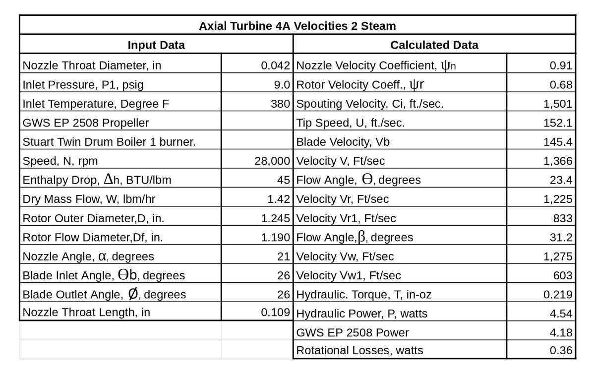
I suggest you try keeping the portions of the housing that contains the ball bearings at a temperature low enough to prevent overheating the bearings. This will increase the heat loss of the steam and lower the efficiency but not as dramatically as you probably suspect. I revised the spreadsheet shown in the post I am quoting to include the turbine efficiency and add the specific speed, Ns, specific diameter, Ds, and the rotor tip speed to spouting velocity, U/Ci, and show it below. This is a test with the highest turbine inlet temperature I have run and the housing cooled by air at room temperature blowing over it. After the test ran long enough to stabilize the temperatures, the turbine inlet temperature was approximately 380 F and the housing temperature was about 212 F at the turbine exhaust and the actual turbine efficiency was 22.3%. The specific speed for this test was Ns = 1.1 and the estimated efficiency of Figure 10 shown in the previous posts is approximately 20% for a Terry Turbine. The report decided to use the Terry Turbine rather than an axial turbine because they felt it was better in the tiny sizes. Axial Turbine 4A that uses the rotor you built exceeded the efficiency expected for the Terry Turbine even with the heat lost to the housing. I think this shows that the heat loss might not be as large as you expect.
Hope this helps,
Byron
 19 March 2025 at 12:48 #789560
Turbine Guy
Participant@turbineguyHi Mike,
I tried to follow the article in the link you gave in your last post but I could only understand the points they were trying to make but not how likely it would cause problems in our tiny models. Our small turbines tend to run relatively high loads for their size and this might prevent the oscillations from occurring. I looked through some of my books on turbines but all of them just dealt with simple sleeve type journal bearings and no mention of the types of problems indicated in this report so this might only occur in special cases. The report was well written and the examples very interesting but like you, I didn’t try to follow the mathematics.
Thanks for mentioning the link,
Byron
19 March 2025 at 15:36 #789580Turbine Guy
Participant@turbineguyIn the previous posts I’ve shown methods for estimating the efficiency of turbines and how using the specific speed, Ns, helps take into consideration many things that affect the efficiency. Figure IV, 24 from the report ‘A Study of High Energy Level, Low Power Output Turbines’ by D.H. Silvern and Dr. O. E. Balje published in 1957 shown below has worked well for me for estimating the performance of my model turbines. This figure adds the condition of small blade numbers for axial turbines which the report indicated would be less than 66 blades and adds the specific diameter, Ds, that includes the size of the rotor OD. The report indicated that this figure was applicable for Terry Turbines with blade numbers greater than 40 blades. The 22.3% actual efficiency of Axial Turbine 4A given in the spreadsheet shown in the 16 March 2025 post was for Ns = 1.1 and Ds = 13.8. The estimated efficiency for these values of Ns and Ds from Figure IV, 24 is approximately 22% showing how adding the additional considerations gets the estimated efficiency very close to the actual efficiency.

 22 March 2025 at 14:56 #790015
Mike Tilby
Participant@miketilby23489Hi Byron
Many thanks for the advice about bearings. I have thought before about keeping the bearings cool but there are three factors that make this difficult. Firstly, the current design of the turbine has the bearing embedded in the end cover of the turbine so any attempt at isolating it thermally would mean a major re-design. Secondly, moving the bearing outside the main turbine casing would mean making the rotor shaft longer. I have tried to keep it as short as possible to minimise problems with balancing and shaft distortion at high rpm. I think I may well run into problems with balancing the already long rotor. Lastly, I think that the small size of the turbine makes thermal isolation difficult because heat gets conducted quickly across short distances, even thin layers of insulation, so especially through metal.
Regarding the principles described in that Dyrobes paper, I too felt very unclear about the significance for a miniature turbine where I assume the major force acting on the rotor seems likely to be that resulting from imbalance and I guess the direction of that force will be constantly changing.
I have been searching for dental bearings with cages made of different materials to the ones I have alreay. I found these:
They are very similar to the dental bearings I already have but it seems they have cages made from PEEK or TORLON which are resistant to much higher temperatures. At 10 bearings for £12 they seem worth trying so I’ve just bought some. My current bearings are rated at up to 250,000 rpm and these more modern ones are for up to 500,000 rpm which seems amazing to me. My aim is to run at a mere 50,000 rpm.
Regarding the topic of using specific speed calculations – I am still in the slow process of reading about that in my text book by Shepherd.
Thanks again
Mike
25 March 2025 at 19:25 #790454Turbine Guy
Participant@turbineguyHi Mike,
I searched for manufacturers that would give the operation limits for the bearings in the size range you are looking for. Lily Bearing Link had the following information for two bearings that show the limits for maximum speed with lubrication and lower maximum temperature and maximum speed without lubrication and at a higher maximum temperature. You can see from these examples how much lower the load and maximum speed must be to operate at the maximum temperature and without lubrication. I’m sorry I couldn’t find examples using the same units to illustrate this, but I thought the limits shown would show what is required to operate at 500,000 rpm or at 500 F. The bearings require cooling and lubrication like provided by running as an air turbine in the dental handpieces to reach the 500,000 rpm limit. The loads and speed are significantly reduced to operate without lubrication and at the maximum temperature. The Lily R144 bearing appears to be capable of running at 500F without lubrication at the 50,000 rpm speed you would like to run at if you can keep the loads below the limits.
Part Number SR144K2TLZN
System of Measurement Metric
Bearing Type Ball
Structure Smooth
Seal Type Single shield
Ball Bearing Type Angular contact
Contact Angle 18 °
Bore Dia 3.175000 mm
Bore Dia Tolerance -0.004mm to 0
Outer Dia 6.35 mm
Outer Dia Tolerance -0.004mm to 0
Width 2.38 mm
Width Tolerance -0.04mm to 0
Ring Material AISI440C Stainless Steel
Ball Material Si3N4
Cage Material Torlon
Dynamic Radial Load 240.26 N
Static Radial Load 75.64 N
Max Speed (X1000 rpm) 500
Lubrication Required
Shaft Mount Type Press Fit
Temperature Range -40 to 120 ºC
ABEC Rating P4 (ABEC-7)
RoHS Compliant
WeightPart Number R144 Ceramic Bearings
Ring Material Silicon Nitride
Cage Material PEEK
Full Complement
Balls Material Si3n4
System of Measurement Inch
Bearing Type Ball
For Load Direction Radial
Construction Single Row
Seal Type Open
Bore Dia 0.125000″
Bore Dia Tolerance -0.0003″ to 0″
Outer Dia 0.25″
Outer Dia Tolerance -0.0003″ to 0″
Width 0.093700″
Width Tolerance -0.005″ to 0″
Dynamic Radial Load 14 lbf
Static Radial Load 4 lbf
Max Speed (X1000 rpm) 53.6
Lubrication Without
Shaft Mount Type Press Fit
ABEC Rating ABEC-1
Radial Clearance Trade No C0
Radial Clearance 0.00008″ to 0.0005″
Ball Dia 0.039410″
Ball Qty 7
Temperature Range -176 to 500 °F
RoHS Compliant
REACH Compliant
Weight 0.11 gHope this helps,
Byron
27 March 2025 at 22:03 #790843Mike Tilby
Participant@miketilby23489Hi Byron
Thanks very much for looking into the details of those bearings. I had looked at Lily Bearings which seem to be a very large Chinese manufacturer of bearings who do not seem to sell direct to end users. But I could not find a company that retails bearings branded as Lily. The bearings I have bought (but not yet received) were sold by a Chinese company that sells parts of dental equipment to dentists etc and I wonder if they were made by Lily.I did not look at the properties as closely as you have and I assumed that if the bearings I have already bought could run wet or dry at high speeds then other bearings made of the same materials (i.e. stainless steel races and ceramic balls) would also probably be O.K. espcially if their rated maximum speed was a lot higher. The cages of bearings I already have are made from nylon and that has a low thermal tolerance and so I was very pleased to find bearings with cages made from more thermo-tolerant plastics.
The R144 bearings have both races and balls made of ceramic and cages made of PEEK. The very high temperature tolerance stated for these bearings 500 F = 260 C seems to exceed the properties of its Peek cages since the tensile strength of Peek is about 105 MPa at 20 C but drops to about 18 MPa at 200 C.
In contrast the temperature tolerance of SR144K2TLZN bearings which have ceramic balls but stainless steel races is stated as only 120 C. However, its cages are made of Torlon which is better able to resist high temperatures than Peek. The properties of Torlon depend on its type but these vary from
110 to 200 MPa at 20 C dropping to about 50 to 110 MPa at 200 C. Thus the materials used for the cages of these bearings do not seem to reflect the temperature limits.Another and very important difference between the two bearings is the precision rating shown as the ABEC value which is 7 for the SR144K2TLZN bearings. This is very high since the scale is 1 to 8 and the bearings I have ordered from China are also rated at 7. The ABEC value for the R144 bearings is 1 i.e. the lowest for a precision bearing. I guess that this is a major reason for its maximum speed being only 53,600 rpm. I wonder if the lower precision rating is also related to its lower maximum dynamic load (14 lbf = 62 N) for the R144 compared to 240 N for the SR144K2TLZN bearings.
Does the above seem reasonable to you? This is a great example of how one has to try to make sense of all sorts of specialised topics just to design one component. I am not confident in my ability to understand these factors but these bearings are cheap so I am fairly happy to try them out and see how they perform and how long they last.
If they prove useless I should be able to insert an alternative type of bearing into the same turbine casing such as the graphite option.
Thanks again for the new data which has triggered me to look more deeply into these things.
Mike
27 March 2025 at 22:29 #790847Mike Tilby
Participant@miketilby23489Hi again
I just noticed I was wrong about the ABEC scale. Wikipeia gives this info:
“There are five classes, which are named using the first five odd numbers:
1 (widest tolerance)
3
5
7
9 (tightest tolerance)The naming scheme is inverse with the tolerance, i.e. higher numbers means lower tolerance. The higher ABEC classes (lower tolerance) provide better precision, efficiency, and the possibility of greater speed capabilities, ….
Bearings not conforming to at least ABEC 1 cannot be classified as precision bearings because their tolerances are too loose.
Mike
28 March 2025 at 20:34 #790974Turbine Guy
Participant@turbineguyHi Mike,
I’m not sure how much the precision affects the load capacity, but the higher load capacity of the bearing with a precision of 7 running at 500,000 rpm indicates it has substantial effect. I assumed it was most important for cases that require the least movement in the bearing to get the best accuracy. The precision does affect the cost, so buying a lower quality should save money. The higher clearance might also be needed in bearings running at very high temperatures to give the space necessary for thermal expansion. The bearing with the precision of 1 showed the radial clearance that was probably required for the operation up to 500 F. The bearing with the precision of 7 limited the maximum temperature to 250 F and did not show the radial clearance.
Thanks for your comments,
Byron
29 March 2025 at 06:31 #791003Mike Tilby
Participant@miketilby23489A further thought came to mind. The thermal expnsion coef. for the AISI440C stainless steel races of the SR144K2TLZN bearings is 10.2 10^-6 m/m degC whereas the coef. for the Si3N4 ceramic used for the balls is 2.5 – 3.5. So as the temperature increases this difference will act to increase the clearance between races and balls, although by a very small amount. Could this be a factor in limiting the working temperature? If so, it might be most relevant to operation at the highest speeds i.e. several hundred thousand rpm. The R144 bearings with the high temperature tolerance have both races and balls made of ceramic so there will be no differential expansion apart from that resulting from the greater circumference of the outer race compared to the inner race.
Mike
29 March 2025 at 18:02 #791071Turbine Guy
Participant@turbineguyPublished designs for graphite bearings show delivery of lubricant at the mid-point and though a hole leading into an axial groove along the bore of the bearing. Arranging for water to be delivered via a radial hole at the mid-point will be difficult so I plan to deliver it to one end – if it is needed at all. (As mentioned in a previous post, the PV value may be less than the 15,000 limit for graphite). I think end delivery of water is worth a try and I’ll be able to assess the effect of lubricant delivery on rotor speed etc. I think enough water will make its through the running clearance of the bearing but, if not, then one possibility could be to make a very fine axial groove in the graphite to allow water to penetrate further along the journal.
That’s more than enough from me. Sorry to have taken up so much space on your thread Byron.
Mike


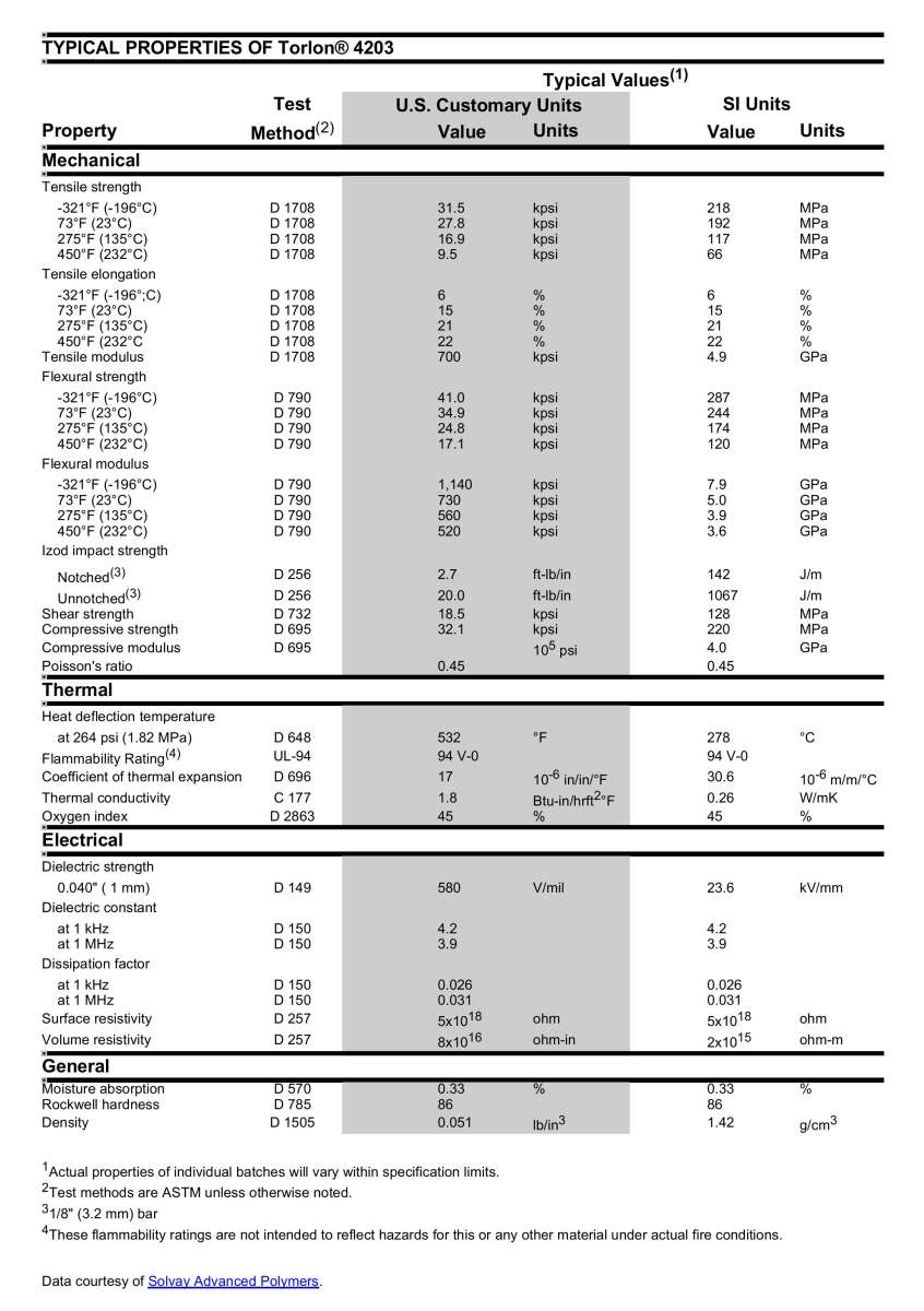
I copied the parts from the quoted post that described what you planned to do with a graphite bushing and the drawing and pictures that helped show the concept. I think you could use this same scheme to cool a dental ball bearing. I believe that all the materials used in dental ball bearings must be compatible with water since the handpieces need to be steam cleaned and also have water injection ports. The phenolic cage in the dental ball bearings I use is porous and wicks up moisture that helps lubricate and cool the bearings when the air driving the dental turbine is dry. This is the reason these bearings do not require lubrication. The following information describing the materials for cages was copied from TBP. The phenolic cage would require more water since its maximum operating temperature is lower than torlon. The following spreadsheet shows the a grade of torlon that can operate at 450 F so the maximum operating temperature of 500 F given by Lily in the previous post is probably correct.

 30 March 2025 at 22:50 #791189
Mike Tilby
Participant@miketilby23489Hi Byron
Thanks very much for finding that data on cage materials. It is very interesting. I like your idea to pump water into the bearing. I would be worried about pumping a lot in to cool the bearing because it might increase drag on the bearing components but a small rate of flow might still have a useful cooling effect and could reduce frictional heat by acting as a lubricant. Is this the sort of thing you had in mind? It could even be possible to adjust the flow rate of water and see the effect on turbine performance.
Mike
31 March 2025 at 14:47 #791262Turbine Guy
Participant@turbineguyHi Mike,
You should only need a trickle of water. Just enough to keep the temperature low enough. I think if you can do that, the small amount of water would also help lubricate the bearings like you said.
Good luck with your project,
Byron
22 April 2025 at 21:59 #794616Turbine Guy
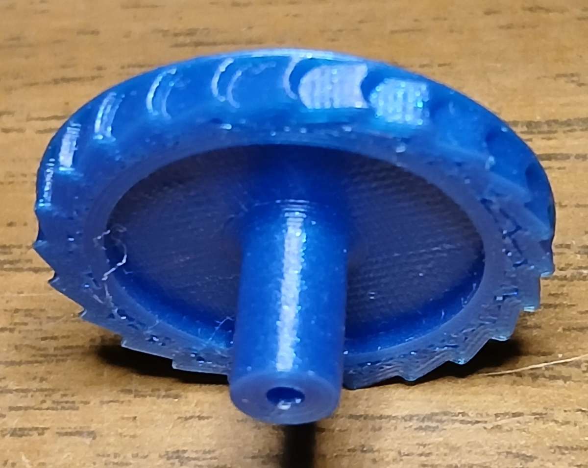
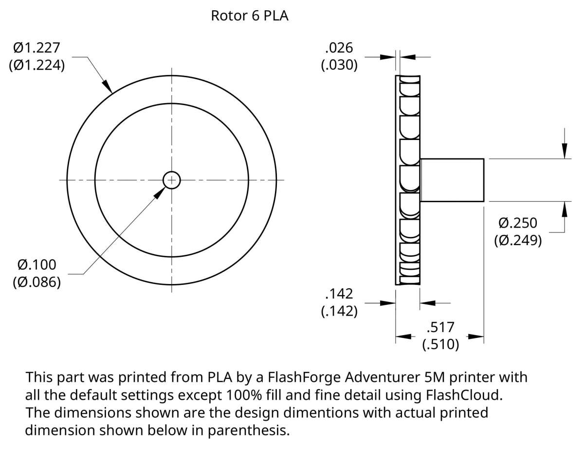
Participant@turbineguyI purchased a Flashforge Adventurer 5M 3D printer to print some of the 3D solids I have made in Onshape rather than having them printed by Shapeways. Since I only have a Chromebook for a computer, I selected FlashCloud for setting up the 3D models for printing. This was because FlashCloud and my Chromebook are cloud based and FlashCloud is created by the same company that made my printer. FlashCloud requires being in contact with the printer to operate properly. I first tried printing models Flashforge had added to FlashCloud or that came installed in the Adventurer 5M printer. I had problems with the printer filament I first tried due to binding of the film on the roller. I found that film binding on the roller was a problem with that manufacturer so I bought another roll of film made by Flashforge that users said the nonbinding of the film on the rolls was one of its best features. Once I had good filament, the printing of Flashforge’s solid models couldn’t be much simpler. All I had to do was select a model and use the default parameters for my printer. When you follow FlashClouds instructions for connecting the printer, it can see if your printer is turned on and send the printing instructions directly to the printer. The first few prints I made were using all the default parameters and the printed parts looked good but default settings used the minimum amount of fill to speed up the printing and reduce the amount of filament used. When I tried adding the first 3D model made by me with Onshape, the scale of the model was off by a factor of 25.4 because my solid model was made in inches. The stl file must be made in millimeters which Onshape and probably most other CAD programs can easily do. After I started making the stl files in metric units the scale showed correctly but the view of the part was not very good compared to what I could see in a stl file viewer. I decided to ignore the view and try printing a part. The following drawing shows how the design dimensions compared with the actual printed dimensions and the two parameters I changed from the default settings to make the printed part solid and as accurate as possible. As you can see from the drawing, most of the dimensions were quite close to the design value. The center hole was off the most but could easily be corrected by increasing its size. The following photo shows the printed part that is a model of a more traditional Stumpf type of rotor without the overlapping pockets. You can see from the photo that the surfaces that turn the flow are quite smooth and should work reasonably well with this model. I had originally planned on having the model cast from bronze so I minimized the wall thicknesses to reduce the amount of material to keep the cost down. Some of these walls are too thin to be strong enough for plastic like PLA. The extended part I intended to grip with a collet chuck is an example of making too thin of a wall. When I gripped that part with the collet chuck it was strong enough to allow machining of the outer surfaces like the face that the inner ball bearing would contact. The PLA is not the easiest material to machine at least I haven’t been able to get the smoothest machined surfaces. When I tried opening up the center hole for the rotor shaft, each time I passed a drill into and back out the collet chuck loosened and had to be retightened. I have never had this happen before so I assume this was due to making the part weaker each time material was removed even though I was only going up one drill size at a time. I will design this rotor for use with plastic like I had to do changing from metal to plastic on some of the parts printed by Shapeways. I am hoping I can show what works for me printing my own parts. I welcome any comments for making better printer parts from plastic. I chose PLA since this was recommended by Flashforge and is what the default settings in FlashCloud were made for.


-
AuthorPosts
- Please log in to reply to this topic. Registering is free and easy using the links on the menu at the top of this page.
Latest Replies
Home › Forums › Stationary engines › Topics
-
- Topic
- Voices
- Posts
- Last Post
-
-
Boiler Design – issue 4765
1
2
…
8
9
Started by:
Charles Lamont in: Model Engineer & Workshop
- 27
- 209
-
16 July 2025 at 01:42
 lezsmith
-
TurboCAD – Alibre File Transfers.
1
2
Started by:
Nigel Graham 2 in: CAD – Technical drawing & design
- 11
- 37
-
16 July 2025 at 00:46
blowlamp
-
I’m Under Pressure
1
2
Started by:
howardb in: Related Hobbies including Vehicle Restoration
- 17
- 32
-
15 July 2025 at 23:56
howardb
-
How many spokes do I really need?
Started by:
 Fulmen
in: Related Hobbies including Vehicle Restoration
- 6
- 16
-
15 July 2025 at 23:37
howardb
-
Suds tray sealant
Started by:
Dave S in: General Questions
- 6
- 6
-
15 July 2025 at 23:26
Paul Mills 4
-
Silver steel crankshaft
1
2
Started by:
teamricky in: Stationary engines
- 8
- 31
-
15 July 2025 at 22:44
teamricky
-
What Did You Do Today 2025
1
2
…
7
8
Started by:
 JasonB
in: The Tea Room
- 33
- 177
-
15 July 2025 at 21:54
Nigel Graham 2
-
Error-Message of the day
Started by:
 Michael Gilligan
in: The Tea Room
- 8
- 14
-
15 July 2025 at 20:42
 Robert Atkinson 2
-
Electronic leadscrew pitching error
Started by:
 paulg 1
in: Introduce Yourself – New members start here!
- 4
- 20
-
15 July 2025 at 20:33
 JasonB
-
Sat nag
1
2
Started by:
duncan webster 1 in: The Tea Room
- 23
- 45
-
15 July 2025 at 20:02
Andy Stopford
-
Farm Boy
1
2
…
4
5
Started by:
Dalboy in: I/C Engines
- 15
- 106
-
15 July 2025 at 19:52
Dalboy
-
motor and switch wiring Myford ML7
Started by:
1957jmh in: Workshop Tools and Tooling
- 5
- 9
-
15 July 2025 at 17:31
Charles Lamont
-
“swedish iron”
Started by:
moonman in: Materials
- 15
- 21
-
15 July 2025 at 16:52
Dave Wootton
-
Old plastic handled screwdrivers
Started by:
 Dave Halford
in: Workshop Tools and Tooling
- 13
- 15
-
15 July 2025 at 14:49
Georgineer
-
Another Day … Another ScumBag
1
2
Started by:
 Michael Gilligan
in: The Tea Room
- 15
- 36
-
15 July 2025 at 10:50
Graham Meek
-
Adjustable spanner thread direction
Started by:
 jimmy b
in: Workshop Tools and Tooling
- 9
- 13
-
15 July 2025 at 08:25
 Nicholas Farr
-
Screw cutting 1.25mm pitch on a Colchester Student.
Started by:
Kevin Nicholls in: Manual machine tools
- 7
- 17
-
15 July 2025 at 06:53
larry phelan 1
-
Volt/amp meter
1
2
Started by:
duncan webster 1 in: Electronics in the Workshop
- 15
- 43
-
15 July 2025 at 06:15
 Michael Gilligan
-
Variable DC power supply?
Started by:
Andrew Tinsley in: Electronics in the Workshop
- 4
- 10
-
14 July 2025 at 17:27
Andrew Tinsley
-
Indicators – vehicle
Started by:
Speedy Builder5 in: Electronics in the Workshop
- 4
- 6
-
14 July 2025 at 06:02
Speedy Builder5
-
buying machine tools from aliexpress experiences?
Started by:
Jake Middleton-Metcalfe in: Manual machine tools
- 16
- 20
-
14 July 2025 at 02:13
Neil Lickfold
-
Electroplating questions
Started by:
Baldric in: Help and Assistance! (Offered or Wanted)
- 3
- 3
-
13 July 2025 at 13:42
noel shelley
-
Difficulty in sourceing 2.5mm s/s ‘Full’ nuts
Started by:
Greensands in: General Questions
- 7
- 12
-
13 July 2025 at 09:22
Roger Woollett
-
Rotary valve engine
Started by:
AStroud in: Stationary engines
- 2
- 3
-
13 July 2025 at 08:49
AStroud
-
Sanjay’s Banjo Engine
Started by:
 JasonB
in: Stationary engines
- 3
- 12
-
13 July 2025 at 06:50
Diogenes
-
Boiler Design – issue 4765
1
2
…
8
9
-


