Model Turbines
Model Turbines
Home › Forums › Stationary engines › Model Turbines
- This topic has 606 replies, 28 voices, and was last updated 12 July 2025 at 16:28 by
Turbine Guy.
-
AuthorPosts
-
14 April 2024 at 18:15 #725830
Turbine Guy
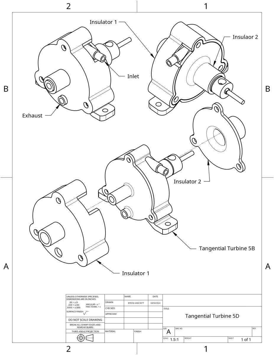
Participant@turbineguyI decided to try to insulate Tangential Turbine 5B by adding a 1/16” thick layer of Nylon over most of the outside surfaces of the housing and cover as shown in the following drawing. I call the new assembly with the added insulation Tangential Turbine 5D.
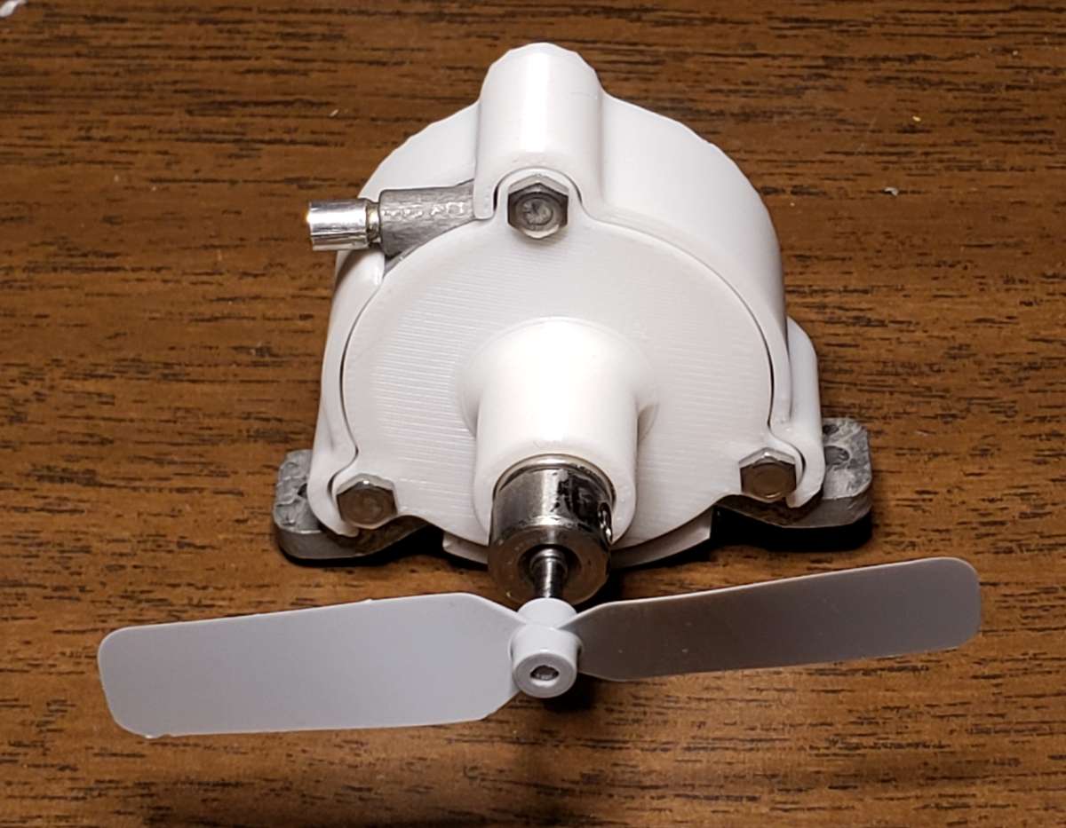
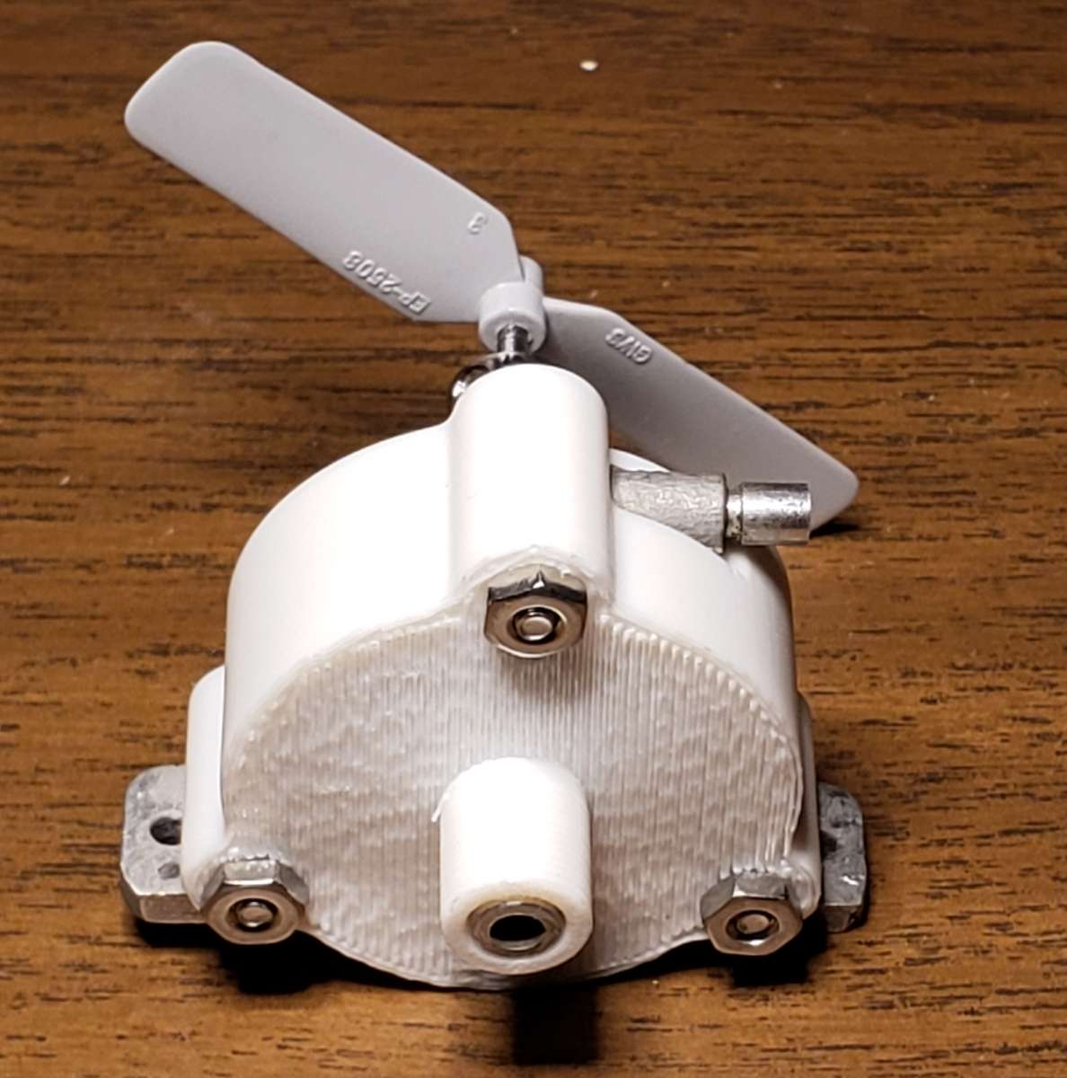
Since the insulators did not have to be very precise or need much strength I asked a friend to print them from Nylon on a home printer. The following photos show the printed insulators installed on Tangential Turbine 5B. As you can see from the photos, the prints came out very good on the first attempt. I thought the insulation would raise the performance significantly by reducing the heat lost to the cold air being blown over the turbine by the propeller. I have not got any improvement in efficiency running on steam regardless of the pressure tried after several tests even though the performance running on air after the test is always as good as before each test. I don’t see any logical reason that I shouldn’t get at least a little better performance by adding the insulation. I haven’t seen any indication of rubbing or binding. I will see if I can find if there is a problem.

 19 April 2024 at 17:01 #726556
Turbine Guy
Participant@turbineguyMike Tilby told me that I might be expecting too much from the insulation I added as described in the last post. He shared with me a very interesting 2 part article that explained how adding insulation with too high conductivity could actually increase the heat loss. The nylon I am using for the insulation is a poor enough insulator that this might be my problem. I decided to see if I could get a good estimate of the actual heat loss. I ran a test of Tangential Turbine 5D and measured the temperature of the housing and outer surface of the insulation using the Stuart Twin Drum boiler, turning the GWS EP 2508 propeller, and keeping the boiler at a output pressure of 40 psig with the globe valve. The housing quickly warmed up to a temperature of 163 F and the outside of the insulation had a temperature of 106 F with the propeller blowing air over the turbine. These temperatures stayed almost the same for the remainder of a 11.5 minute run. When steam ran out and the turbine started to lose speed, the temperature of the outside of the insulation started to rise very quickly since the convective heat transfer changed from forced to natural convection. The outside temperature of the insulation went up so quickly and then started to drop very slowly that I wasn’t ready to get the highest temperature when the propeller stopped turning. I have to remove the wick burner immediately after the water is boiled out since it has almost full flame at the end of the run. I purposely start with ½ cup of water since I know it will run out before the wick burner starts to run out of alcohol. This allows me to have approximately maximum output of the wick burner for the full length of the run. This also allows me to know exactly how much water was used. The turbine speed, housing temperature, and outside temperature of the insulation all stayed about the same after the turbine warmed up with the globe valve at the same opening for the rest of the run. This length of run with very stable conditions should give me the data I need to find a good estimate of the heat lost from the turbine housing and cover with the 1/16” thick nylon insulation. The following equation is what I used to find the heat loss through the insulation. I used the value of 0.144 W/mK given by Shapeways for the thermal conductivity of their printed nylon assuming the printed nylon of my insulation would be about the same. I used the heat flow average area of the insulation since the following reference indicated that if the ratio of the outer radius to the inner radius of the insulation was below 2, the error in using the average area is less than 4%. The largest ratio on any part of the insulators was 1.45 for a very small portion with the remainder being less than 1.2. Since the shape of the insulators was relatively complex I used my 3D Cad program Onshape to find the areas. This program will give the total area of all the surfaces that are highlighted which made getting accurate areas very easy.
Q=kA(T1-T2)/s = (0.0833)(0.049)(163-106)/(0.0052) = 45 Btu/hr = 13 W
Where:
Q= Heat Transfer, Btu/hr
k= Thermal Conductivity = 0.0833 (Btu Ft)/ (hr degree F Ft^2)
s= Insulation thickness = 0.0052 Ft
A= Insulation Average Area = 0.049 Ft^2
T1= Housing and Cover Temperature = 163 degree F
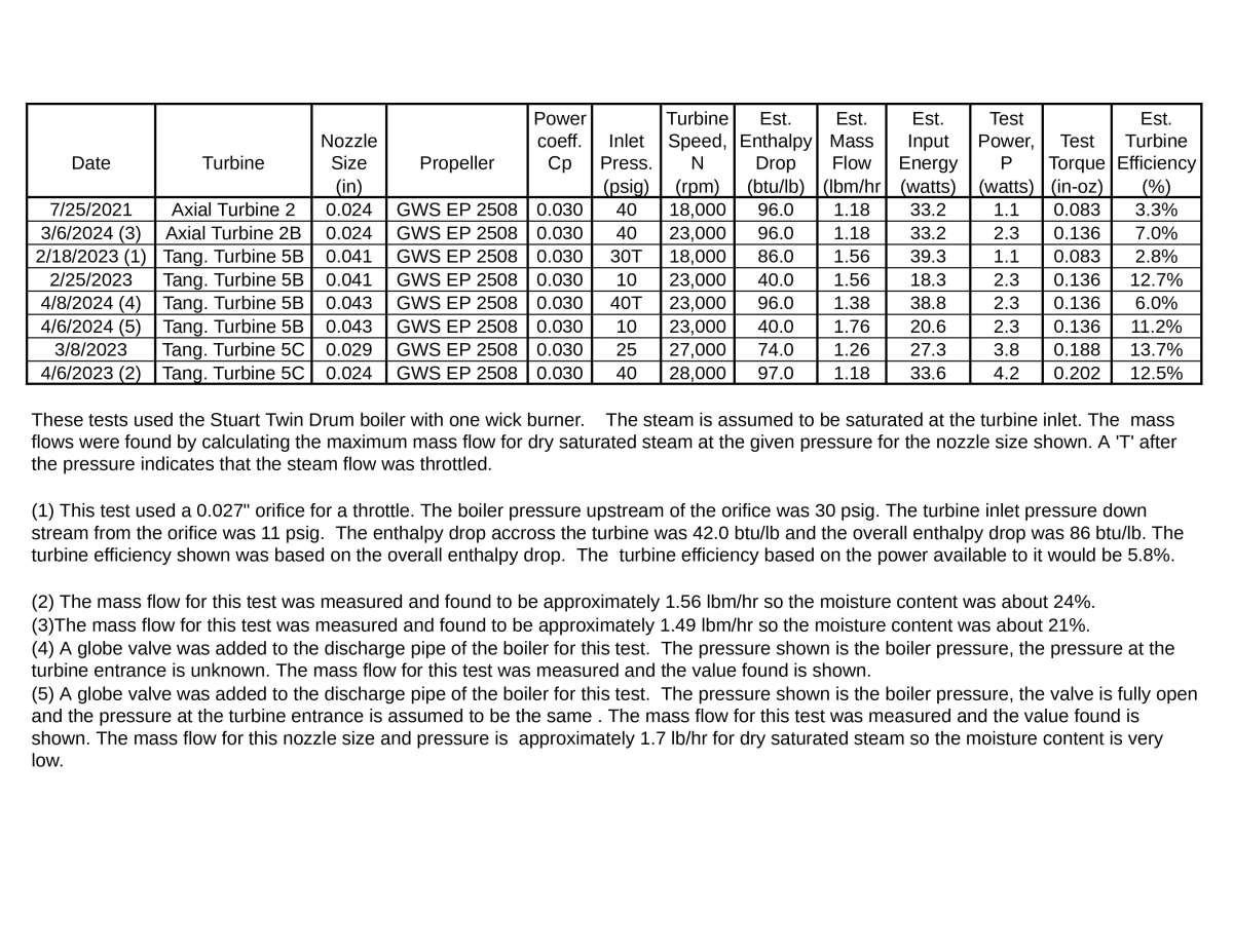
T2= Insulation Outside Temperature = 106 degree FThe run time was about the same as the 4/8/2024 test shown in the following table that was discussed in the 9 April 2024 post on page 21. This test was run the same way so the input power to the turbine of 38.8 watts was approximately the same and is an example of how consistent the power available for the same settings has been. The heat lost through the insulation estimated to be approximately 13 watts is about 34% of the energy input to the turbine but a large part of that probably occurs after the steam has flowed through the rotor.
I ran another test with everything the same except with the insulators removed. The run time was almost identical with the boiler pressure held at a constant 40 psig, so the energy output of the boiler was approximately the same. The housing temperature stayed at approximately 176 F for the rest of the run after a short warmup. Mike was right, the nylon insulation actually added slightly more heat loss.
Reference: An Introduction To Heat Transfer by M. Fishenden and O. A Saunders published July 1950.
 25 May 2024 at 16:40 #732405
Turbine Guy
Participant@turbineguyPosted by duncan webster on 27/01/2023 22:59:24:
I’m not entirely clear about the bearing shims, but when I worked on high speed gearboxes many years ago we used bearing preload washers to lightly axially load the bearings. This prevented skidding between the balls and race, but allowed for differential expansion as things warmed up.prof Chadfock used a more sophisticated but similar setup in the QuornEdited By duncan webster on 27/01/2023 23:00:17The shim washers I have been using are flat with an ID that is a close fit to the shaft and an OD that is small enough that it has clearance with the outer race of the ball bearing. These were what was used in Radial Turbine 1. My last turbines are using the ball bearings used in the Star high speed dental handpiece. The rotor in this handpiece uses wave washers to accomplish what you described. The wave washers used in the Star handpiece are available at a very low cost and would work in all my turbines using the same bearings. I’ve noticed some noise that I think is caused by the rotor moving back and forth in the small (<0.005″
 gaps. The wave washers would probably eliminate this noise and extend the life of the bearings.
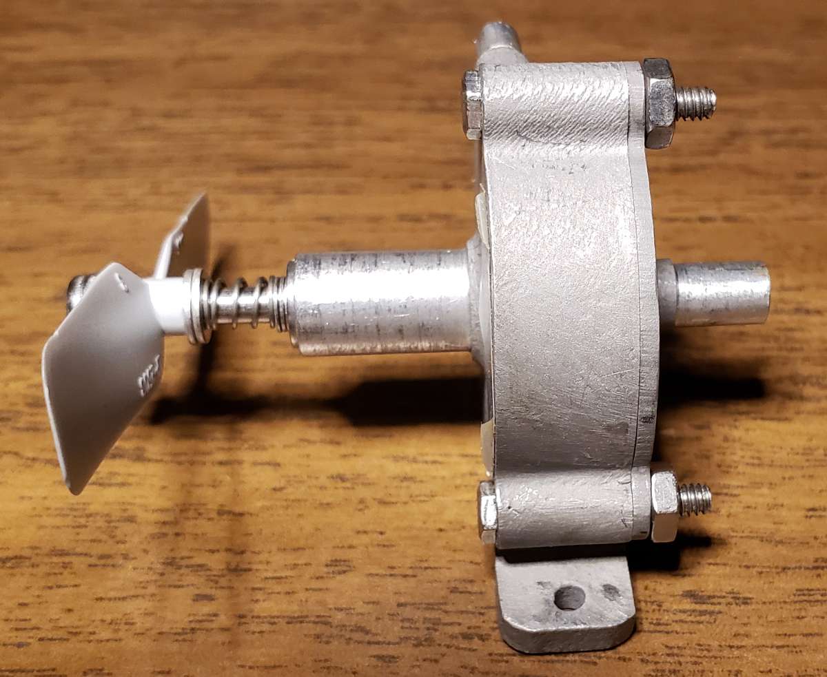
Edited By Turbine Guy on 28/01/2023 15:51:07The wave washers that are used in the Star dental handpiece would not work with my turbines so I looked for another way to use a spring to absorb the expansion and contraction due to the large difference in temperature running on steam and air. The following photo shows a spring I used in place of the set screw collar on Tangential Turbine 5B to keep the rotor pressed against the inner ball bearing regardless of the change of temperatures. The spring used has a spring rate of 11.25 lb/in and a minimum compressed length of 0.14”. The compressed length of the spring in the setup shown in the photo is 0.23” so it is well above the minimum. The free length of the spring is 0.25” so the amount of compression is 0.02” and the resulting force is approximately 0.22 lbs (3.5 oz.). The maximum thrust from the propeller I have got from any test I have run so far is 1.9 oz. The existing preload will handle the maximum propeller thrust for any propeller that pushes the rotor away from the inner bearing. I ran Tangential Turbine 5B on air before and after adding the spring and the pressure required to turn the GWS EP 2508 propeller to a speed of 28,000 rpm actually dropped from 12 psig to 11.5 psig after the spring was added. Apparently keeping the rotor positioned correctly with the nozzle added more power than the extra force on the ball bearings took away. Adding the spring also eliminated the noises mentioned in the post I quoted. It took me a while to try using a spring preload, but thanks Duncan for suggesting this.
 31 May 2024 at 21:03 #733575
Turbine Guy
Participant@turbineguyI ran Tangential Turbine 5C on steam from my Stuart Twin Drum boiler a few times and each time the maximum pressure got lower. I assumed there was leakage around the nozzle insert, so I removed it. The nozzle bore in the insert had increased above the 0.024” (0.61mm) size it had in the first tests. This was probably due to my passing the drill through the insert bore before each test to make sure it was clean. Apparently I opened the insert up a little each time I cleaned the nozzle.
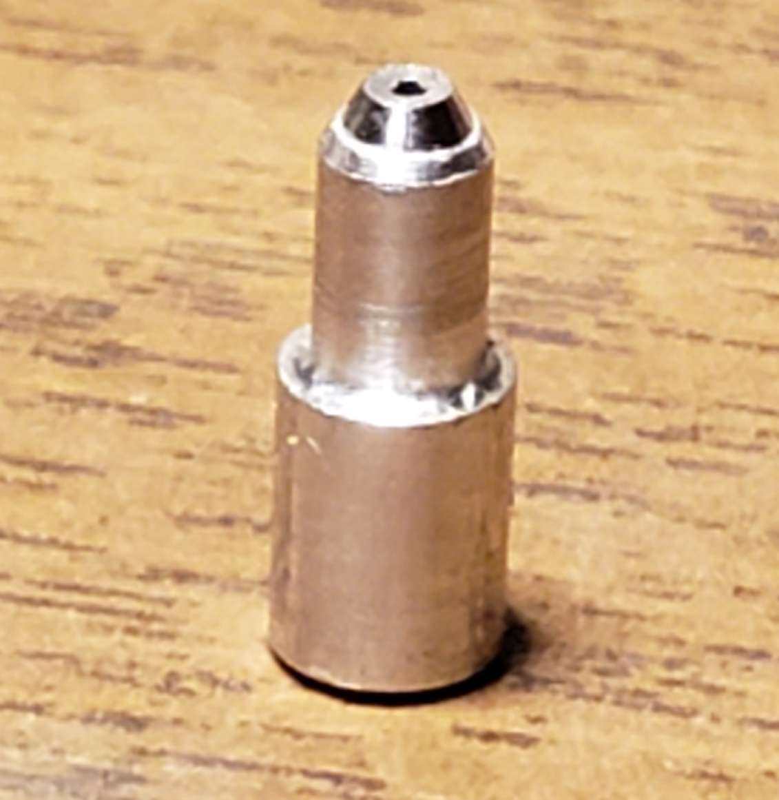
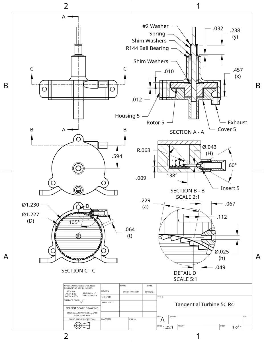
The insert removed in the quote was made from aluminum. I made an insert out of stainless steel surgical tubing described in the 7 March 2024 post that worked well in Axial Turbine 2B so I decided to make another insert for Tangential Turbine 5C. The following photo shows the stainless steel insert protruding out of the aluminum inlet tube. I got about the same performance with the new stainless steel insert as with the aluminum insert so no update to the tables showing the test results is needed. I updated the following drawing to show the size and placement of the new insert and the new settings of the preload spring described in the last post.

 1 June 2024 at 17:51 #733690
Turbine Guy
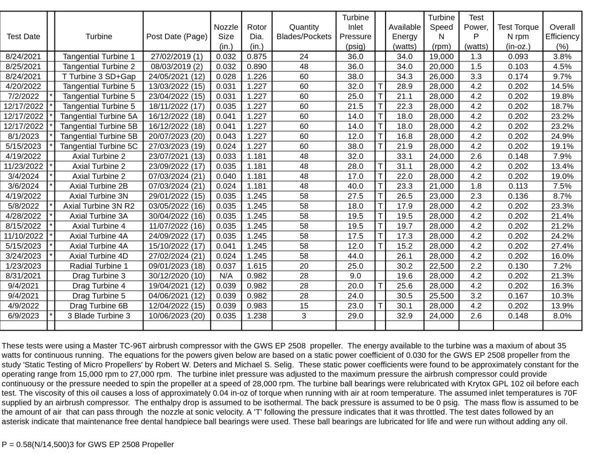
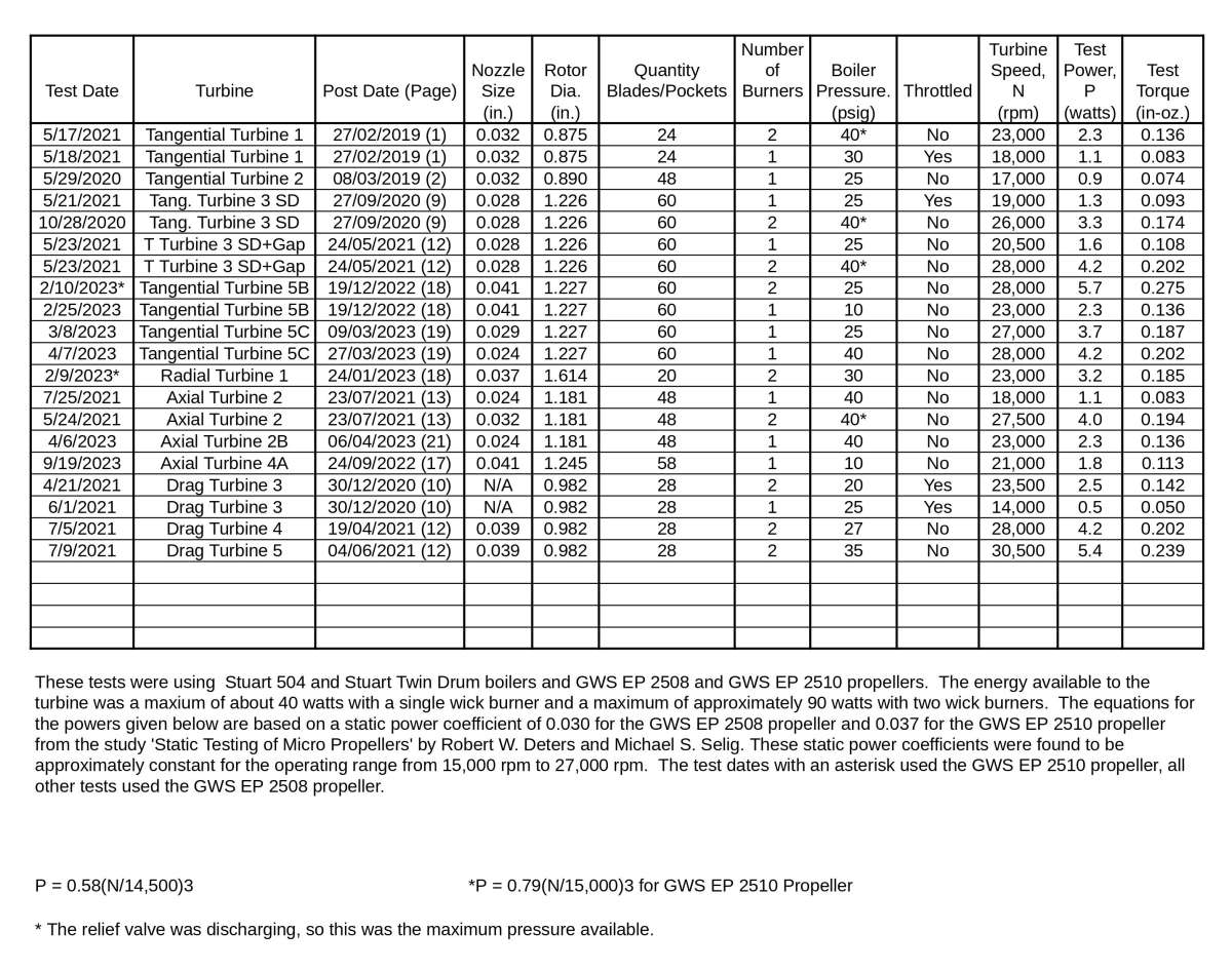
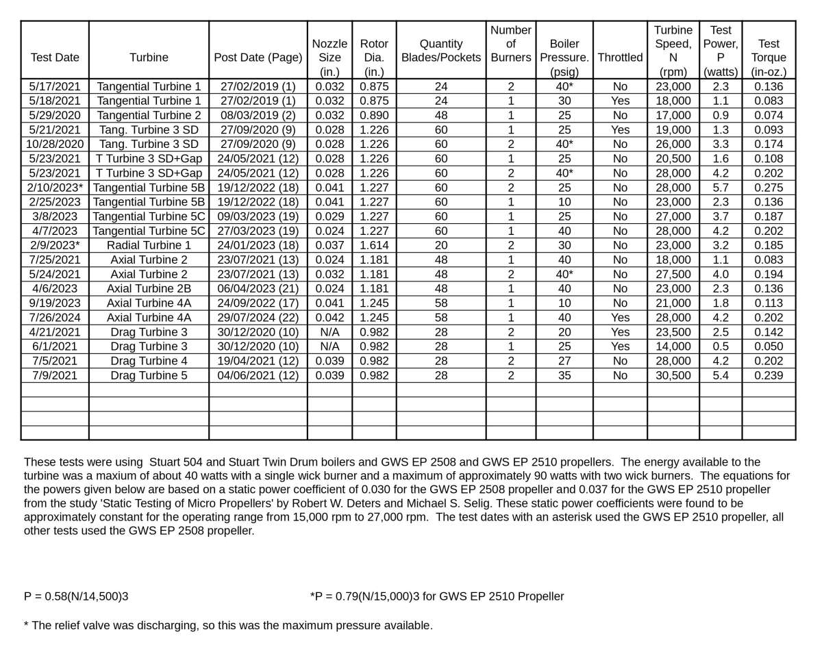
Participant@turbineguyThe following tables are the last updates of the test results for each of the turbines I have tested. Since these tests have occurred over a several year span, the date of the post that best describes the turbine and the page number the post is found on is shown by each test. A new number was given to each turbine when a major change was made. For example Tangential Turbine 1 was called Tangential Turbine 2 after the rotor was changed from one with 24 pockets to one with 48 pockets. Changes that could be made using the same housing and rotor were given a letter after the number to indicate the configuration. For example Tangential Turbine 5A had no cover, Tangential Turbine 5B used a cover, and Tangential Turbine 5C used a cover and an insert in the nozzle. Tangential Turbine 5 can be changed from each configuration back to any other configuration by adding or removing parts. These results show the best performance I was able to get for each configuration for the nozzle size shown. For example, the latest update of Tangential Turbine 5C described in the last post added a preload spring and changed the nozzle insert from aluminum to stainless steel. Both of these changes helped the longevity of the turbine but did not increase the performance, so the test with the closest nozzle size shows the best performance for this configuration. The closest nozzle size shown in the table for tests with air for Tangential Turbine 5C for the existing nozzle size of 0.025”, is the 0.024” of the 5/15/2023 test. That test shows the best performance running on air for Tangential Turbine 5C with a nozzle size close to 0.024”. The 27/03/2023 post on page 19 describes the test and shows details of the turbine. Similarly the 4/7/2023 post gives the best performance for running with steam and the 27/03/2023 post on page 19 shows details of the turbine. Sorry I have to be so long winded in describing how to use the tables. I have made so many tests and configurations, I thought it might be helpful to describe the information I intend to show.

 29 July 2024 at 16:46 #744179
Turbine Guy
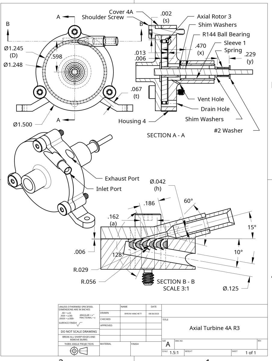
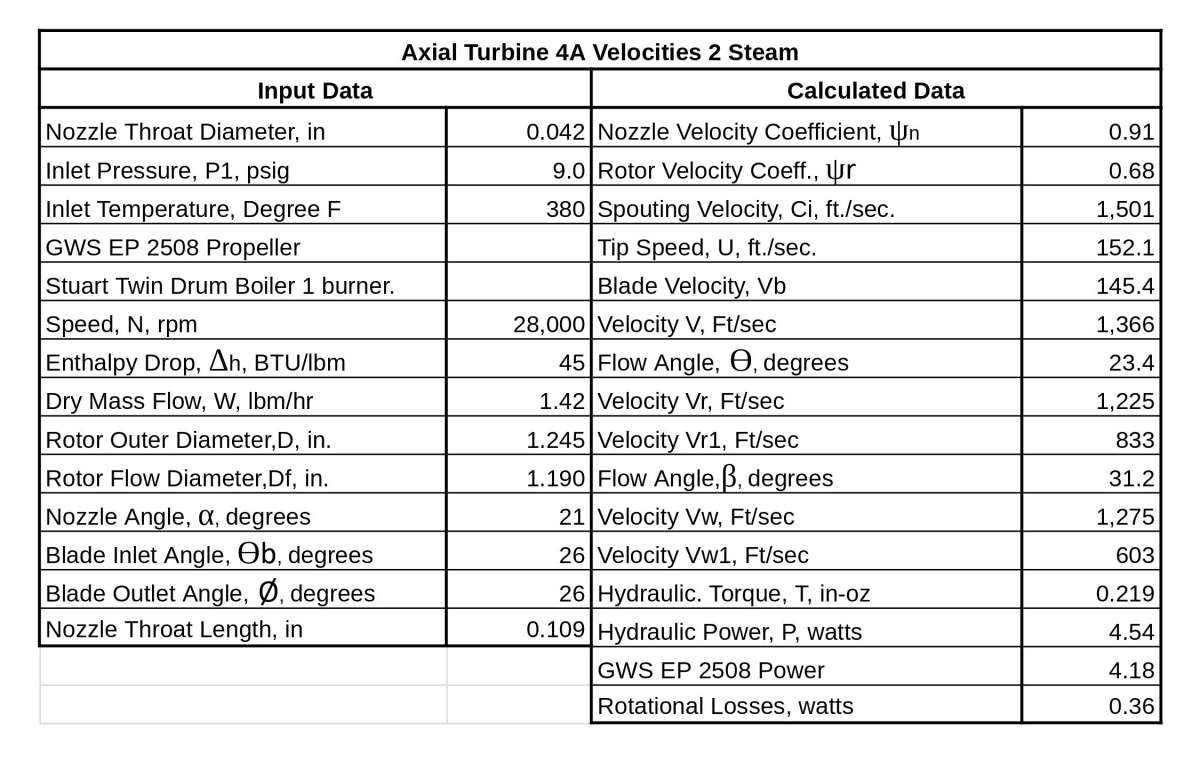
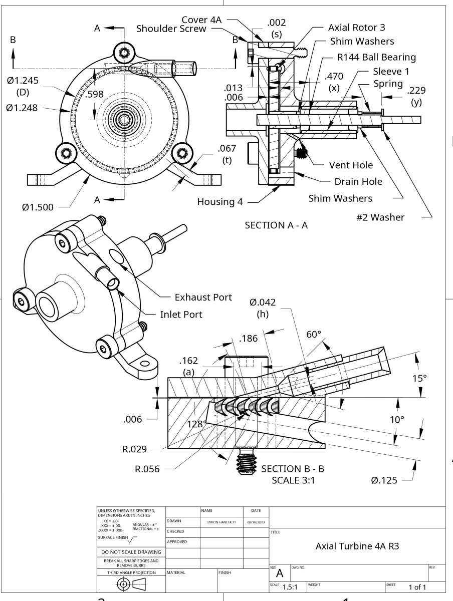
Participant@turbineguyI replaced the set screw collar with a spring on Axial Turbine 4A similar to what I did to Tangential Turbine 5C as described in the 25 May 2024 post. The following drawing shows the position of the parts and the compressed length of the spring. I ran a test with my Stuart Twin Drum boiler using the throttle valve to hold the boiler pressure at 40 psig and the steam coming out of the exhaust was invisible so the steam stayed superheated all the way through the rotor. After the turbine warmed up the throttle valve stayed in the same position and the turbine speed remained constant for the rest of the 11 minute run. The following spreadsheet has this test added. This is the first steam test I have made with superheated steam so I ran another test the same way with identical results.

 30 July 2024 at 12:23 #744284
Mike Tilby
Participant@miketilby23489Hi Byron
Your mentioning of the pre-load spring in a recent post started me thinking about the design of my own very incomplete turbine. I’m sorry if this question has been covered in previous posts. I could not find the information, but there are a lot of posts!
If I understand correctly, the spring applies a light pressure that tends to force the inner rings (races) of the bearings together thereby ensuring the balls remain in contact with their grooves. That means the inner ring of at least one of the bearings must be able to slide along the shaft under light pressure whereas the outer rings cannot move together because of their flanges. So I am wondering what sort of fit you have between the inner rings and the shaft.
In my turbine the inner rings of the bearings are unable to move because they are lodged against shoulders on each end of the shaft. However, one of the outer rings of the bearings could exert the pre-load if I fitted a suitable spring, providing it was not an interference fit in its housing. Does that sound O.K. to you?
Actually I have hit a problem in the design for my own turbine which, as you know, is a long way from reaching a stage where it can rotate. I have been planning to use the dental bearings rated at 250,000rpm with ceramic balls in s/s races. These can operate dry or wet with water (which is certain to make its way into the bearing). But they have nylon cages and that limits their maximum working temperature. This issue has become more serious now that I have modified the design of my boiler. The boiler now allows highly superheated steam (e.g. 50psi, 250 degC) to be supplied to the turbine. This should benefit the operation of the turbine for a number of reasons but it is not feasible to thermally isolate the bearing at the hp end from high temperatures. Ball bearings made of stainless steel balls and cages will have better tolerance to high temperatures but they have lower max. rpm, they will need to be lubricated with oil and oil+water may give a problem. So I am wondering about using a graphite bearing, at least for the hp end. This will be self-lubricating and also compatible with water. Any thoughts will be very welcome.
Best wishes, Mike
30 July 2024 at 16:55 #744334Turbine Guy
Participant@turbineguyHi Mike,
There are a lot of posts, but the preceding post by Duncan Webster I quoted is the only discussion about pre-load on any other page in this thread.
The ball bearing manufacturers recommend that the inner race be a light press fit on the shaft. The precision shafting I use would provide this fit and I would follow their recommendation if I did not need to disassemble the turbines so often to try different settings or options. To ease assembly and disassembly I make the shafts a very close slip fit with the inner race of the ball bearings.
The wave washers used by the Star dental drill mentioned in Duncan’s post fit between the ball bearing flange and the housing. This allows the outer race of the ball bearing to move in the housing to absorb the expansion or contraction. This is the method preferred by the bearing manufacturers and should work for you.
As I mentioned to you a while back, I have used graphite bearings to overcome the problems you mentioned. These bearings were used in a steam turbine that had superheated steam in the same range of temperatures that you plan to use. The advantage I had with that turbine was its exhaust emptied into a condenser and ran at below atmospheric pressure. This allowed me to use the vacuum to pull condensed water through the graphite bushings to lubricate them and have the water run back into the condenser to be used over again. This worked really well but I don’t know if you would have near enough water if you relied only on the amount condensed by the hot housing. Graphalloy claims that their air lubricated bearings have operated at speeds of 100,000 rpm as shown in the Graphalloy Link. They probably could provide you more information.
The test of Axial Turbine 4A I added in the last post uses the excellent rotor you made for me. I felt that this test gets the conditions closer to what it should operate in. I plan on discussing a little more about this test in one of the next posts.
Thanks for the update,
Byron
31 July 2024 at 08:19 #744442Mike Tilby
Participant@miketilby23489Hi Byron
Many thanks for those helpful comments. Yes, I had not forgotten that you told me previously you had used graphite bearings in a marine turbine. I have been assuming, although I feel very uncertain about this, that ball bearings would give lower frictional losses than a plain bearing. Is that why you use ball bearings in your miniature turbines?
It is the need to withstand high temperature that make me think again about graphite. In 1962 a Mr. Gordon published a description in Model Engineer (10th May 1962) of a very ingenious and very small model turbine-powered boat he had built. That had graphite bearings made from carbon rods he removed from torch batteries. I tried to upload a picture but for some reason I’m told the image is not valid (I’ll send you a copy of the article).
I don’t recall you mentioning Graphalloy before and that is a product I knew nothing about. After reading your last post looked into it and understand that it is graphite impregnated with metal, the actual type of metal depending on the application. Apparently it is stronger and more thermally conductive than normal graphite. It sounds specialised and expaensive but I think I’ll contact the company to see if they can supply a small quantity at an affordable price. However, I already have some graphite rods that I bought from the UK compny Erodex. I obtained this to make rotating seals but it is actually a grade of graphite that is recommended for low load bearings (it is grade KC-67 made by Toysanto). I think shall try using that initially. It is nice and easy to machine.
I have just seen that Toysanto also make grades of metal-impregnated graphite and that is recommended for highly loaded bearings. This webpage has a useful table of data. https://www.toyotanso.com/Products/Mechanical_carbon/data.html
Best wishes, Mike
31 July 2024 at 20:21 #744548Turbine Guy
Participant@turbineguyHi Mike,
I do use ball bearings in my model turbines to increase the performance. The dental ball bearings I am currently using increased the performance significantly over the shielded oil filled ball bearings and even more for the self lubricating bushing I first tried. This was due to the large reduction in friction that is very important in the miniature turbines.
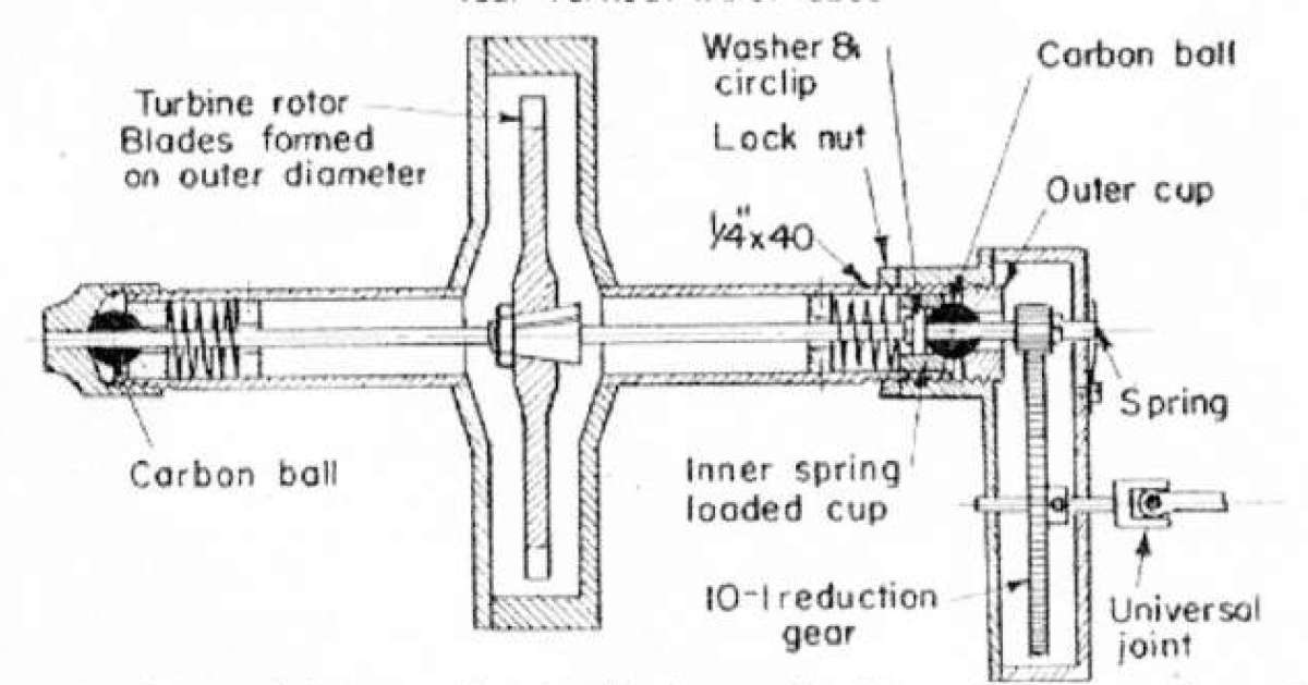
I was able to print the portion of the article you sent that showed Mr. Gordon’s turbine as shown below. I copied this because it illustrates the reasons I believe he was successful using the graphite bearings. His spacing of the bearings a long way apart eliminates the tilting of the rotor and increases leverage to resist the force of the impact of the steam on the rotor. His leaving the rotor open all around except for the nozzle outlet eliminates pressure on the entire face of the rotor. Pressure on the rotor face has ruined the ball bearings in some of my model turbines as I have discussed a few times in this thread. His use of a 0.045” diameter shaft (the only dimension of the turbine I found in the article) keeps the velocity of the shaft OD low. Self lubricating bearings are usually limited by pressure x velocity, so limiting the velocity increases the amount of load allowed. The small diameter reduces the friction torque reducing the power loss. The long length of bearing housings give a large heat transfer area to heat conduction area that helps lower the temperature at the bearings. The use of springs to absorb the expansion is the latest change to my top two turbines and is another thing I liked about his design.
I suggested the Graphalloy because it is available from many sources in the USA and has a good reputation but is more expensive than some graphite bushings. I’m sure Europe has just as good sources as you are finding. Graphalloy has a design PV limit (psi x ft/min) of 12,000 and has been used in air at over 100,000 rpm. The upper speed limit and PV limit are what you should try to find.
Hope this helps,
Byron
 1 August 2024 at 17:01 #744617
Turbine Guy
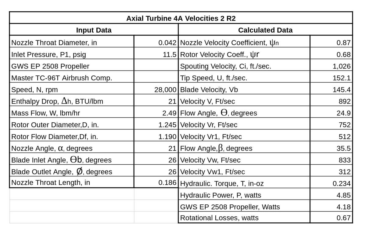
Participant@turbineguyI mentioned in the 29 July 2024 post that the steam stayed superheated all the way through the turbine in the test described in that post. I found the mass flow out of the boiler to be 1.4 lb/hr by the 11 minute time required to boil out ½ cup of water. I estimated the temperature of the steam entering the turbine by finding what the temperature and pressure at the throat of the nozzle had to be for this mass flow. This was a process of iteration guessing the temperature and pressure and using the corresponding enthalpy drop to find the throat velocity and specific volume of the steam. The mass flow for dry steam can be determined with the throat velocity and specific volume. It took several iterations to find the estimated pressure and temperature at the inlet of the turbine that resulted in the mass flow found in the test. The following spreadsheet shows the estimated inlet temperature, pressure, and enthalpy drop for the test described in that post and the performance of the turbine for that test. On the second test I measured the housing temperature and it stayed at 211 degrees F for the entire length of the run after the turbine warmed up to its operating temperature. I also added below the spreadsheet for the test with air for comparison with the test with steam like I did in the 7 April 2023 post on page 20 for Tangential Turbine 5C. This post and the 7 April 2023 post show the performance on air and steam of the two best turbines I have tested. Axial Turbine 4A discussed in this post is a traditional De Laval type of Axial Turbine and Tangential Turbine 5C discussed in the 7 April 2023 post is similar to the open pocket Stumpf type of Tangential Turbine but with overlapping pockets.

 2 August 2024 at 10:59 #744705
Mike Tilby
Participant@miketilby23489Thanks Byron, for your post about graphite bearings which I found very interesting and helpful. I’d not heard of PV limit before and your message prompted an investigation. I hope the following is not over-the-top but someone might find it useful.
Regarding PV value, It is simple for me to calculate the velocity term (V) but the pressure term (P) seems less straightforward. A rough estimate based simply on the weight of the rotor puts the PV value for my turbine at about 7,000 with P in psi and V in ft/min. However, I assume the effects of rotor imbalance will cause the load to be greater than just the effects of gravity. However, that aspect seems difficult to estimate, even if I knew the extent of imbalance.
I could find very limited mechanical specifications on-line about the various grades of Graphalloy. Most detail was in this document: https://www.graphalloy.com/html/PDF/DS112.pdf . That sates that bearings running dry will give no trouble if designed such that (RPM * load / length of bearing) is less than 46,000. In this calculation load is in lbs weight rather than pressure and length is in inches. To me that seems a strange calculation since it takes no account of shaft diameter.
The same document also says that the above formula is based on:
“a conservative “PV” factor of approximately 12,000, where P is bearing load in psi and V is in feet per minute shaft surface speed. However, for many special combinations of speed and load, the values given by the formula can be considerably exceeded. For submerged bushings, running on a liquid film, the values can usually be increased by a factor of 7 to 10. GRAPHALLOY bushings have been operated at 60,000 RPM submerged. With gas lubrication, speeds of 200,000 RPM have been attained.”
This also seems strange to me since surface speed cannot be calculated from RPM without knowing the diameter.
The website of the company that made my KC-67 graphite rods (ToyoTanso) does not mention PV factor although they do give many other mechanical properties of their various types of graphite-based materials: https://www.toyotanso.com/Products/Mechanical_carbon/Mechanical_carbon_data.pdf
The company ‘US Graphite’ make graphite products under the name of Graphitar. They give detailed mechanical specifications for their various grades but these do not include PV limits. However, in one document they refer to their products in general when they say:
“The limiting P-V factor for any material varies considerably with operating conditions … lubrication, surface finish, mating material, etc. For dry conditions, a P-V factor of 15,000 should be used. When lubricated, P-V values of 150,000 are acceptable ….” This implies that the PV limit does not vary much between different grades of graphite.
Grade 86 Graphitar material is described as: “A universal grade for lubricated or non-lubricated service. Offers excellent compressive strength, an extremely low porosity and excellent wear resistance.”
The mechanical specifications (e.g hardness, strengths) for this product are fairly similar those for the ToyoTanso graphite grade KC-67 that I obtained. The main difference is that the temperature limit of the grade 86 Graphitar is 290 degC whereas the ToyoTanso KC-67 is 350 degC. I assume this difference may be due to the Graphitar being resin impregnated whereas the KC-67 is plain graphite/carbon.
So I feel it is worthwhile trying out bearings made with KC-67.
Thanks again
Mike
2 August 2024 at 19:55 #744806Turbine Guy
Participant@turbineguyThe PV values given in the USA are typically pressure in psi and velocity in ft/min.
Shaft diameter, D in.
Force, F lb.
Bearing Length, L in.
Shaft speed, N rpmP=F/DL psi
V=(3.1416)(D/12)N ft/minPV = (F/DL)(3.1416(D/12)N) = 3.1416FN/12L < 12,000 lb-ft/min.
The shaft diameters cancel out when you multiply P x V.
Graphalloy simplified the formula by putting the constants in the limit.
3.1416FN/12L < 12,000 = FN/L < (12,000)(12)/3.1416< 46,000
The fastest I run my turbines is 28,000 rpm and the length of the ball bearings are 0.109”. If I replaced them with Graphalloy bushings, the maximum allowable force would be as follows.
F=46,000L/N = (46,000)(0.109)/28,000 = 0.18 lb = 2.9 oz.
The 46,000 limit is deceptive, the load must be very small to run at high speeds.
2 August 2024 at 22:02 #744825duncan webster 1
Participant@duncanwebster1The classic DeLaval turbine (single stage impulse) runs very fast. The spindly shaft shown in Turbine Guys drawing above is there to lower the whirling speed, because above the whirling speed the rotor runs on its mass centre, and so any initial imbalance doesn’t load the bearings, and doesn’t shake the foundations. The shaft isn’t continuously flexing, think rotating banana. One of the major losses in non condensing turbines is windage on the fast rotating disc. I was tod when I worked on such devices (a long time ago) that a close fitting casing (or internal shroud) just clear of the wheel reduced this, but I have no knowledge whether this is true. The tomes to consult are by Kearton and Stodola , these links might be the right ones, but no guarantees Stodola Kearton. In my youth the local library would have got copies from the British Library for a small fee, but nowadays it’s either not offered or more expensive than buying off ebay
You should always open the steam valve smartly on a DeLaval so that it passes through its whirl speed quickly and doesn’t have time to build up serious vibration.
2 August 2024 at 22:49 #744833Mike Tilby
Participant@miketilby23489Is it the case that need to accommodate the distortion of the spindle is why the bearings are spherical so that they can self-align with the shaft ends?
I’ve read that close fitting casings reduce the windage effect of disc friction whereby gas (i.e. air and/or steam) gets accelerated on a circular path by proximity to the spinning disc. This gas moves outwards through centrifugal force undergoing more acceleration. Also, more non-rotating gas gets drawn in at the centre and accelerated. When the gas reaches the periphery of the disc it moves away from the disc and is decelerated by friction with the casing. So a circulation is set up. Accelerating the gas requires energy which is taken from the disc and more energy is absorbed because of frictional losses in turbulence during the acceleration. If the gap between disc and casing is kept very narrow this circulation does not take place and the loss becomes that of simple frictional loss which is apparently much less than when the circulation occurs.
Mike
2 August 2024 at 23:24 #744835duncan webster 1
Participant@duncanwebster1That sounds very feasible
3 August 2024 at 07:37 #744886Mike Tilby
Participant@miketilby23489Byron, thanks for explaining the maths simplification behind the Graphalloy equation.
Graphalloy say that with gas lubrication much higher speeds are attainable and I’m wondering what is meant by that. e.g. Does it refer to the introduction of compressed air etc through special small holes as is used in some high speed spindles?
Also US Graphite says that with lubrication, PV values can be as high as 150,000. They do not specify the lubricant but elsewhere I’ve read that water is OK with graphite bearings so I’m wondering if ensuring the bearing is wet will be a good idea. Maybe the hydrodynamic effect will keep the shaft out of direct contact with the graphite?
Nothing is straightforward.
Mike
3 August 2024 at 17:41 #744998Turbine Guy
Participant@turbineguyHi Duncan,
Your mention of the large spacing between the bearings helping keep the shaft stable as the turbine speeds up was probably another reason Mr. Gordon did that.
The few tests I have tried like described in the 22 June 2022 post on page 16 have not shown any measurable difference in performance between wide open space and side clearances of less than 0.01”. This is probably because the rotor diameters and blade heights are so small on my model turbines.
I wasn’t aware of Kearton, but I have seen Stodola referenced many times. Their book would probably be very useful for someone interested in turbines.
Hi Mike,
Mr. Gordons use of the spherical graphite balls was probably to keep the bore concentric with the shaft as it bent like you mentioned. This and what Duncan pointed out are two more reasons his steam turbine was successful.
I thought you would find the way Graphalloy simplified finding the limitations useful.
I think it would be easier to find a way to cool the area around the ball bearings than trying to add water flow or airflow through the graphite bushings to obtain the higher PV limits. I looked in a book on Turbochargers to see what they used for bearings since they run at very high speeds and temperatures. The most common bearings were journal bearings flooded with oil. The racing versions used what were described as very expensive ball bearings that were protected from the heat and flowing plenty of oil. Apparently the extra cost of the ball bearings and much more expensive bearing housings was justified by the improvement in performance.
4 August 2024 at 10:55 #745079Mike Tilby
Participant@miketilby23489Hi Byron
Thanks for the suggestion re cooling the bearings. I agree that would be the ideal way ahead and is the way it is done in large turbines with inlet steam at over 500 degC. In the huge power station turbines and in marine turbines such as the Stal Laval AP series, the bearings are on separate pedestals from the turbine casing. But as I see things, these machines have three big advantages. Firstly: large size. This means the heat has a long way to be conducted between parts exposed to high temperature steam and the hp bearing. Second, they can install numerous seals on the main shaft to keep the steam where it should be. Thirdly, they have sophisticated oil handling equipment to constantly circulate cooled oil through the bearings. In my turbine I have been trying to keep the rotor length as short as possible to minimise the tendency for it to distort at high rpm, especially since my balancing efforts will not be as satisfactory as the professional turbines. If I did extend the shaft and place the bearings outside the main casing, the distance for heat condution would still be quite short. Also I’d have to install some effective high speed shaft seals which would waste power through friction. I do plan to put simple shaft seals between the pressure stages but leakage past these will be less critical since the pressure drops across them will be smaller and escaping steam will simply be going to the next stage rather than being wasted to the atmosphere.
As with everything, compromises are necessary and it is good to discuss these issues. All advice is welcome to help me improve the chances of success.
Mike
4 August 2024 at 17:41 #745119duncan webster 1
Participant@duncanwebster1If your turbine is exhausting to atmosphere, the pressure in the casing is the same as outside, so you don’t actually need much of a seal
4 August 2024 at 18:27 #745146Turbine Guy
Participant@turbineguyHi Mike,
Whatever you choose for a bearing will have to have the surface that contains it at a temperature lower than the maximum temperature enough to conduct away the heat generated by friction. The high friction of dry graphite partially offsets the benefit of its high maximum temperature. Your choice to make a Rateu (pressure staged) type of turbine with multiple rotors makes this much more difficult to accomplish. The heat loss in each chamber must be kept to a minimum. All the successful model turbines I have seen were single stage that greatly simplifies this problem. Having the steam expand to close to ambient pressure lowers the temperature as far as possible. Having a small amount of surface exposed to the steam, like the drawing below of Axial Turbine 4A shows, also greatly reduces the heat transferred to the housing. To be fair, the single stage also lowers the efficiency due to the large amount of energy still in the exhaust steam. Most modelers, myself included, are willing to accept the lower efficiency to avoid the extra complication of pressure staging. I will try to come up with some ways to cool the bearings.
I admire you tackling this problem,
Byron
 4 August 2024 at 18:35 #745155
Mike Tilby
Participant@miketilby23489Hi Duncan
The turbine I’m attempting to build is a 4-stage impulse (i.e. Rateau) design with inlet at 60 psi gauge pressure and exhaust to atmosphere. Ideally the heat drops per stage will be equal and for that the pressures at inlets of the nozzles of each stage would be: 75, 53, 36 and 22 psi absolute. With the hp bearing in the same housing as the rotor there is no steam leakage at that end but otherwise there will have to be a seal to restrain steam at 53 psia from escaping.
The equal heat drops would give equal steam velocities in each stage. The steam velocities would be lower than in a single stage turbine and, compared to a single stage machine, the lower velocity would be closer to the ideal for an attainable blade speed and would be associated with reduced frictional/turbulence losses in the steam. However, these advantages must be balanced against increased frictional losses due to fannage and disc friction for four discs instead of just one and also friction due to the inter-stage graphite seals. Whether I’ll ever get it completed and working is debateable but it’s an interesting (for me) challenge that I’m happy to take on. So far, methods for making rotor discs/blades, diaphragm discs, inter-stage nozzles and inter-stage seals have been worked out and initial versions of the components made. The bearings are the last main piece of the jigsaw – until I encounter the next unexpected problem.
Mike
4 August 2024 at 18:45 #745162Mike Tilby
Participant@miketilby23489Hi Byron
Thanks for those comments which I only saw after I’d posted the reply to Duncan. I think it is the challenge to make a different design that appeals to me rather than wishing to just build a turbine that works. As you say, if I wanted to be sure of making a working turbine I would make a single stage design – and I may well end up using the rotor discs in such a machine. But until then I hope you will continue to humour/advise me in what may be a doomed effort 🙂
Mike
4 August 2024 at 20:04 #745184Mike Tilby
Participant@miketilby23489An after thought on graphite bearings. I am thinking of drilling a small radial hole into the midpoint of the bearing and connecting a fine pipe through which I can pump a small flow of water to both provide lubrication and cool the bearing. The small amount of water would escape into the turbine where it would evaporate in the superheated steam. Supply of pressurised water would come from a tapping on the feed into my flash boiler via some sort of needle valve.
Mike
5 August 2024 at 21:11 #745423Turbine Guy
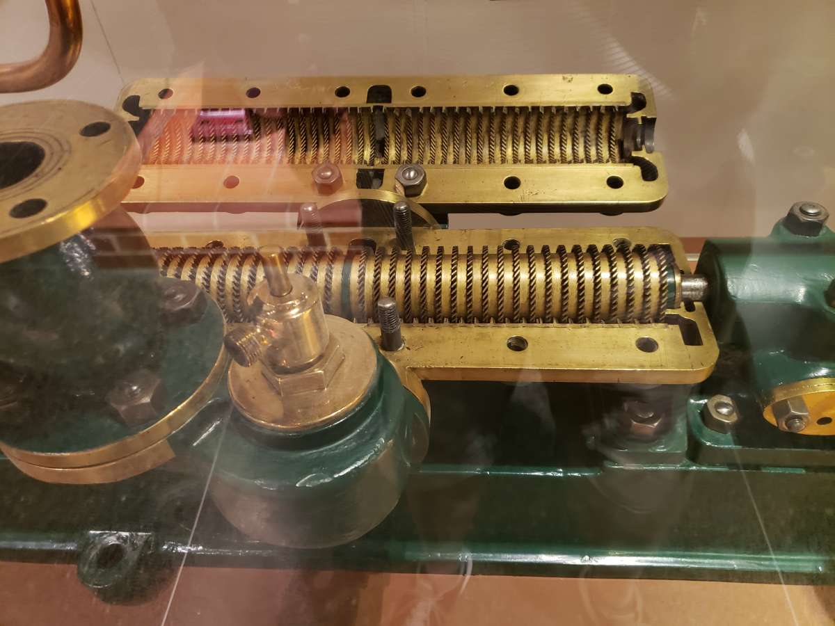
Participant@turbineguyBefore I can make any suggestions for cooling the bearings, I will need to know more about how you plan to make the turbine housing. All the pictures I have found for Rateau turbines have a split housing similar to the following picture I took of an open Parsons turbine. I know the Parsons turbine is a reaction type turbine but this picture shows how the stationary blade plates are split in half with one half attached to the removable top half of the housing and the other half attached to the bottom half of the housing. The details I have seen for Rateau turbines use this same concept for the nozzle plates. This allows the rotors to be fixed to the rotor shaft and complete rotor assembly can be lowered into the bottom housing with the lower half of the nozzle plates installed. The upper housing with the nozzle plates already installed can then be lowered onto the lower housing. This picture also shows that bearings are only at the outer ends of the housing even though there are many stages as appears also to be done with the Rateau turbines. Do you plan to do something similar, or if not, what do you plan to do?

-
AuthorPosts
- Please log in to reply to this topic. Registering is free and easy using the links on the menu at the top of this page.
Latest Replies
Home › Forums › Stationary engines › Topics
-
- Topic
- Voices
- Posts
- Last Post
-
-
TurboCAD – Alibre File Transfers.
Started by:
Nigel Graham 2 in: CAD – Technical drawing & design
- 5
- 11
-
13 July 2025 at 00:00
Nigel Graham 2
-
Silver steel crankshaft
Started by:
teamricky in: Stationary engines
- 4
- 5
-
12 July 2025 at 23:20
Paul Lousick
-
Another Day … Another ScumBag
Started by:
 Michael Gilligan
in: The Tea Room
- 13
- 23
-
12 July 2025 at 22:33
Nigel Graham 2
-
I’m Under Pressure
1
2
Started by:
howardb in: Related Hobbies including Vehicle Restoration
- 17
- 31
-
12 July 2025 at 22:00
Howard Lewis
-
Help for DIY lathe build.
1
2
Started by:
moogie in: Help and Assistance! (Offered or Wanted)
- 16
- 36
-
12 July 2025 at 21:42
Howard Lewis
-
Difficulty in sourceing 2.5mm s/s ‘Full’ nuts
Started by:
Greensands in: General Questions
- 5
- 8
-
12 July 2025 at 21:15
duncan webster 1
-
Electronic leadscrew pitching error
Started by:
paulg 1 in: Introduce Yourself – New members start here!
- 2
- 6
-
12 July 2025 at 21:08
paulg 1
-
New Member From The Isle of Man
Started by:
sprocket 3 in: Introduce Yourself – New members start here!
- 4
- 4
-
12 July 2025 at 20:57
Howard Lewis
-
Farm Boy
1
2
…
4
5
Started by:
Dalboy in: I/C Engines
- 15
- 103
-
12 July 2025 at 18:51
Dalboy
-
The Silver Swan Automaton
Started by:
James A in: Related Hobbies including Vehicle Restoration
- 3
- 5
-
12 July 2025 at 18:46
James A
-
Rotary valve engine
Started by:
AStroud in: Stationary engines
- 1
- 1
-
12 July 2025 at 16:43
AStroud
-
Model Turbines
1
2
…
24
25
Started by:
Turbine Guy in: Stationary engines
- 28
- 607
-
12 July 2025 at 16:28
Turbine Guy
-
Sanjay’s Banjo Engine
Started by:
 JasonB
in: Stationary engines
- 3
- 11
-
12 July 2025 at 16:20
 JasonB
-
“swedish iron”
Started by:
moonman in: Materials
- 11
- 14
-
12 July 2025 at 15:41
moonman
-
Nozzle dot dwg
Started by:
 Michael Gilligan
in: CAD – Technical drawing & design
- 1
- 1
-
12 July 2025 at 14:47
 Michael Gilligan
-
Sat nag
1
2
Started by:
duncan webster 1 in: The Tea Room
- 16
- 30
-
12 July 2025 at 12:30
noel shelley
-
Yet another scam
Started by:
 Dell
in: The Tea Room
- 2
- 2
-
12 July 2025 at 10:16
Bo’sun
-
buying machine tools from aliexpress experiences?
Started by:
Jake Middleton-Metcalfe in: Manual machine tools
- 14
- 17
-
11 July 2025 at 22:26
Versaboss
-
Adjustable spanner thread direction
Started by:
 jimmy b
in: Workshop Tools and Tooling
- 8
- 8
-
11 July 2025 at 22:14
Nimble
-
Chester Champion, warco ZX15 drawbar
Started by:
martian in: Manual machine tools
- 5
- 7
-
11 July 2025 at 21:51
Howard Lewis
-
Bosch PBD 40 bearing upgrade
Started by:
th1980 in: Manual machine tools
- 6
- 12
-
11 July 2025 at 21:33
Howard Lewis
-
Square end on round stock – Milling?
1
2
Started by:
Roger TheShrubber in: Workshop Tools and Tooling
- 17
- 30
-
11 July 2025 at 21:23
Howard Lewis
-
motor and switch wiring Myford ML7
Started by:
1957jmh in: Workshop Tools and Tooling
- 4
- 6
-
11 July 2025 at 21:09
Howard Lewis
-
Old plastic handled screwdrivers
Started by:
 Dave Halford
in: Workshop Tools and Tooling
- 12
- 14
-
11 July 2025 at 17:14
 Robert Atkinson 2
-
Bridgeport ways and wear
Started by:
inline in: Manual machine tools
- 7
- 18
-
11 July 2025 at 09:16
Ian Owen NZ
-
TurboCAD – Alibre File Transfers.
-


 gaps. The wave washers would probably eliminate this noise and extend the life of the bearings.