Model Turbines

Advert

Model Turbines

Home Forums Stationary engines Model Turbines

Viewing 25 posts - 451 through 475 (of 583 total)
  • Author
    Posts
  • #635397
    Turbine Guy
    Participant
      @turbineguy

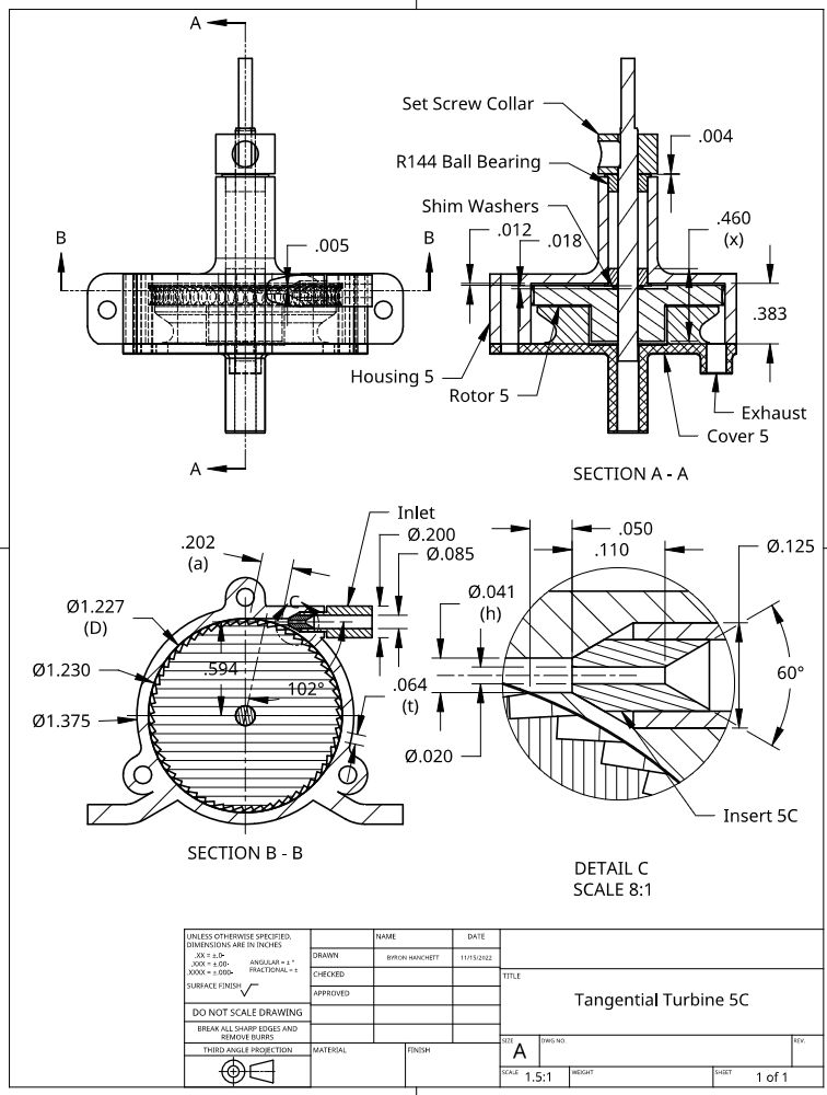
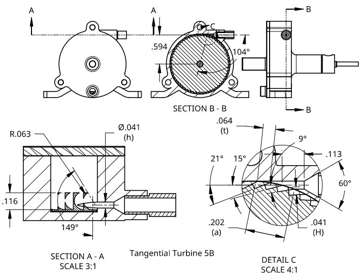
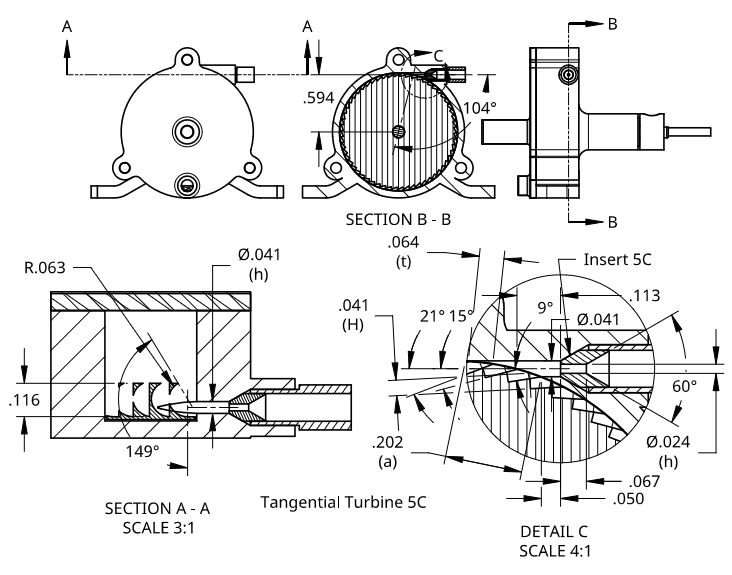
      I am going to try to add an insert like shown in Detail C in the following drawing to Tangential Turbine 5B and call this configuration Tangential Turbine 5C. This will give a minimum distance of approximately 0.050” for the gas to expand to supersonic velocities before contacting the rotor. I’ll start with the throat diameter of 0.020” shown in the drawing and increase the size in steps until I get the pressure below 40 psig running on the Stuart Twin Drum boiler. I believe this will increase the performance shown in the last post for Tangential Turbine 5B.

      tangential turbine 5c.jpg

      Advert
      #635749
      Turbine Guy
      Participant
        @turbineguy

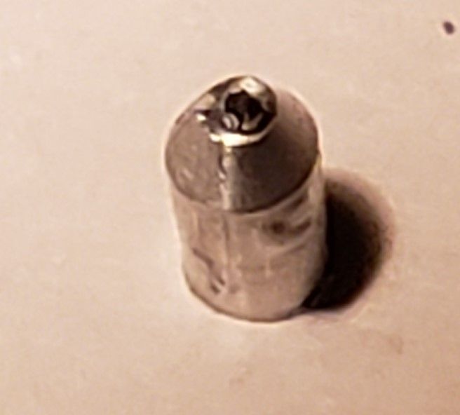
        I tried several times to make the insert shown in Detail C of the drawing in the last post. Each time the drill broke in the bore of the insert. Apparently, the wear of my 37 years old lathe has reached a point that I can’t keep the drill and insert in the necessary alignment. I was able to turn the OD to the correct diameter, make the external and internal tapers, and machine the insert to the correct length. The internal taper was made with a center drill with a 60-degree taper and a 0.020” drill bit size. The maximum length the drill had to pass through was less than the 0.110” shown in the drawing of the last post. The following photo shows the furthest I was able to get. The drill broke the instant it passed through the insert. There was a very tiny amount of the end of the broken off peace extending beyond the end of the insert. I bumped the extended part with a hammer hoping to break it loose but even though the end moved back to even with the face of the insert, it wouldn’t break free. The insert is so small that the photo required a large amount of zoom, but I think you can see that the drill had moved off center. The maximum drilling depth given for the 0.020” drill was 0.150” so I didn’t exceed that recommendation. I ran the drill at 4,000 rpm which is the highest speed of my lathe and moved the drill into the insert very carefully. After four tries, I must concede that this is beyond my skill and the accuracy of my lathe.

        insert 5c photo.jpg

        #636781
        Turbine Guy
        Participant
          @turbineguy

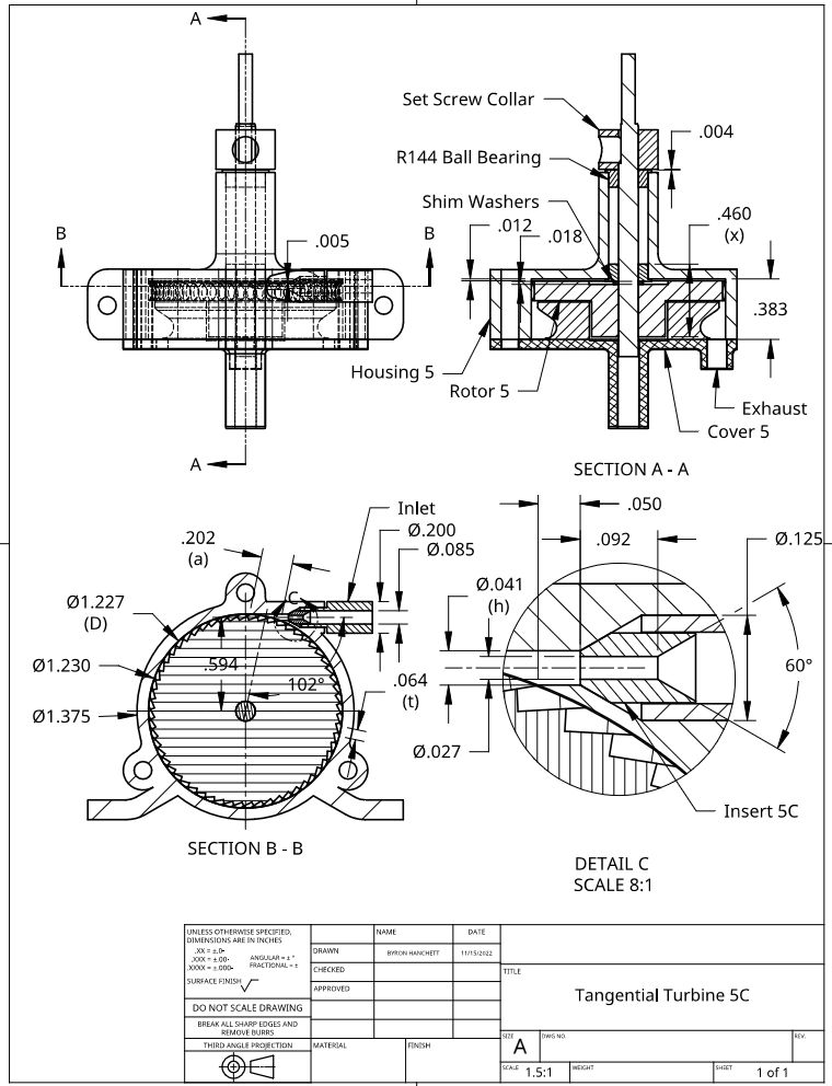
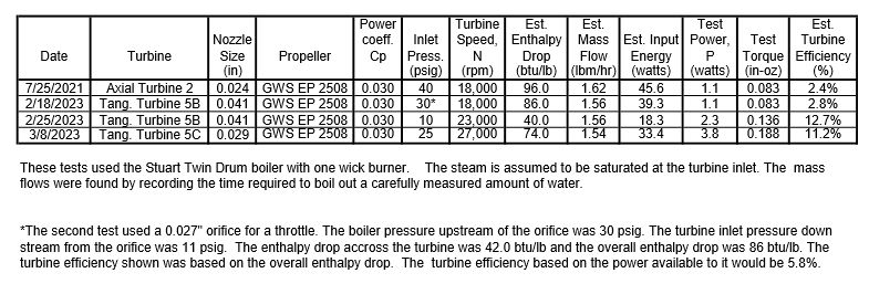
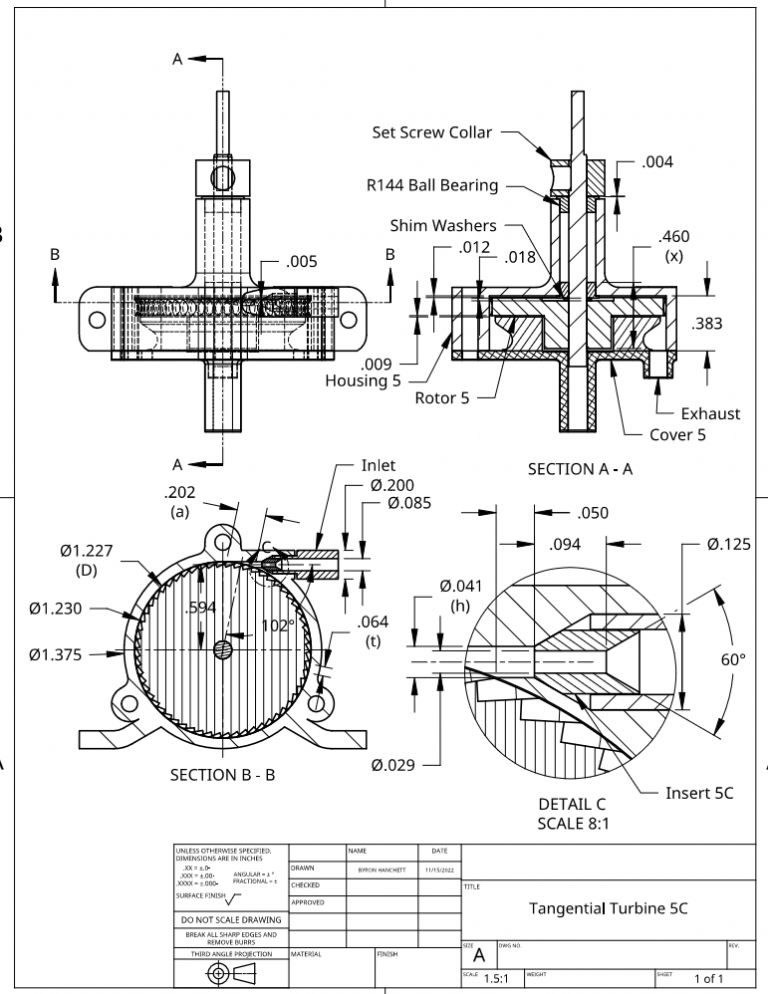
          I was able to purchase a length of surgical tubing with a nominal OD of 0.094” and ID of 0.024” made of 316 stainless steel. The actual ID was 0.027” so I thought that it might be small enough to work for Insert 5C that was described in the last post. Even though the tube was welded, the inside and outside were very smooth and concentric. Having the hole all the way through eliminated the problem of breaking the drills I described in the last post and the insert was very easy to make. The following drawing of Tangential Turbine 5C shows the updated dimensions and the following test sheet shows the performance running with the Stuart Twin Drum boiler. Allowing the space for the steam to expand without increasing the clearance of the sides or top of the rotor appeared make a substantial improvement.

          tangential turbine 5c r1.jpg

          turbine test results 50.jpg

          Edited By Turbine Guy on 08/03/2023 21:03:22

          #636893
          Turbine Guy
          Participant
            @turbineguy

            I noticed that the nozzle size shown in the drawing and test sheet of the last post were different, so I measured it again. The correct size is 0.029” as shown on the test sheet. The following drawing of Tangential Turbine 5C has been up dated to show the correct size.

            When I ran the test of Tangential Turbine 5C shown in the last post, I noticed the speed was periodically dropping and then returning to the maximum speed. This occurred several times until late in the run and then the speed stayed at the maximum until the water ran out in the boiler. This indicated that water was being carried over during the first part of the run. I checked the average moisture content for the entire run and it was approximately 20%. During the time when the speed was increasing and decreasing the maximum speed was about 25,000 rpm. The maximum speed when it stayed steady, was the 27,000 rpm, shown in the test sheet. This change in speed was due to the steam being drier at the last part of the run.

            The performance of Tangential Turbine 5C appeared to exceed the performance of the Saito T-1 steam engine described in the 12/10/2020 Post of the Testing Models thread. This test of the Saito T-1 steam engine with everything the way it came and run with the Stuart Twin Drum boiler; it turned an APC 8×6 propeller at approximately 2,400 rpm. This propeller requires 1.7 watts to run at this speed according to the manufacture’s propeller performance sheets. Tangential Turbine 5C would require a 11.3:1 speed reducer to run at the Saito T-1 speed. This would probably require two stages and assuming the 80% efficiency per stage I found with the test of Radial Turbine 1, the power of Tangential Turbine 5C would be reduced to 2.4 watts. This is still quite a bit better than the 1.7 watts of the Saito T-1 steam engine that was the best performing of any of the small steam engines I tested.
            tangential turbine 5c r2.jpg

            #636931
            duncan webster 1
            Participant
              @duncanwebster1

              On 25/02,Turbine Guy refers to gear efficiency as 80%. This seems low to me, when I worked on gas turbine gearbox design we assumed 97% for each stage. Of course they were very well made gears,and running in ball bearings.

              #636967
              Turbine Guy
              Participant
                @turbineguy
                Posted by duncan webster on 09/03/2023 18:18:25:

                On 25/02,Turbine Guy refers to gear efficiency as 80%. This seems low to me, when I worked on gas turbine gearbox design we assumed 97% for each stage. Of course they were very well made gears,and running in ball bearings.

                Duncan, I agree the 80% efficiency is way below what well made and precisely aligned gears running on quality ball bearings would get with higher power outputs. The tiny turbines I have been testing have so little torque that grease lubricated ball bearings like used in the gear reducer that came with Radial Turbine 1 have a much larger effect on them. I ran a test of Radial Turbine 1 with and without the gearbox described in the 23/01/2023 post on page 22 to confirm this.

                #637650
                Turbine Guy
                Participant
                  @turbineguy

                  My original intent of adding Insert 5C to Tangential Turbine 5C was to get the pressure up to 40 psig with the Stuart Twin Drum boiler like I was able to do with the insert added to Axial Turbine 2 shown in the test sheet of the 08/03/2023 post. As I mentioned in the previous posts, I was not able to get the nozzle size down to the 0.024” diameter Axial Turbine 2 had when it ran at 40 psig with the Stuart Twin Drum boiler. I traced the problem of not being able to drill the nozzle size down to 0.024” to misalignment between the headstock and tailstock of my lathe. I found a used tailstock for a Unimat 3 lathe that was described as being in excellent condition on Ebay. I purchased this tailstock and hope that it will get the alignment good enough to drill the very tiny holes. If the new tailstock allows me to make an insert with a nozzle size of 0.020” as I originally planned, I will start with that size and make tests with very small increases in size until I find what works best. I had no problem removing the existing Insert 5C and Turbine 5B performed the same as before I tried the insert, so I have nothing to loose trying the smaller nozzle sizes.

                  #637957
                  Turbine Guy
                  Participant
                    @turbineguy

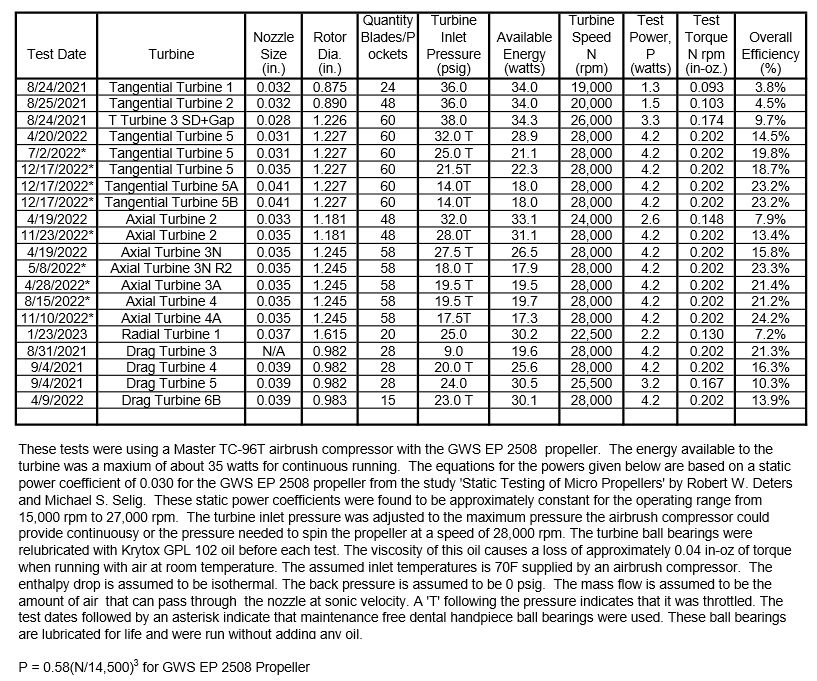
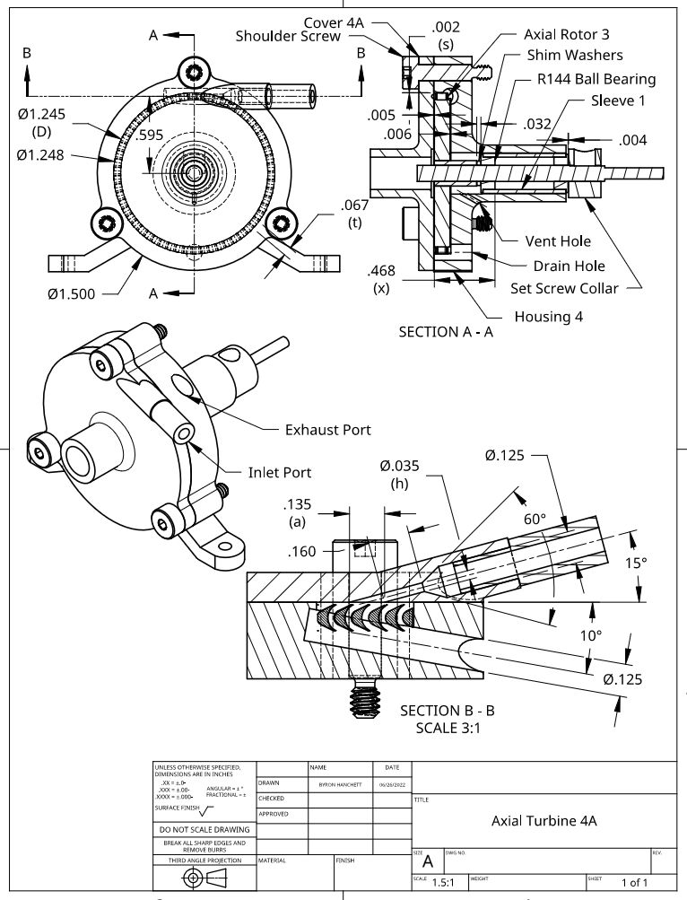
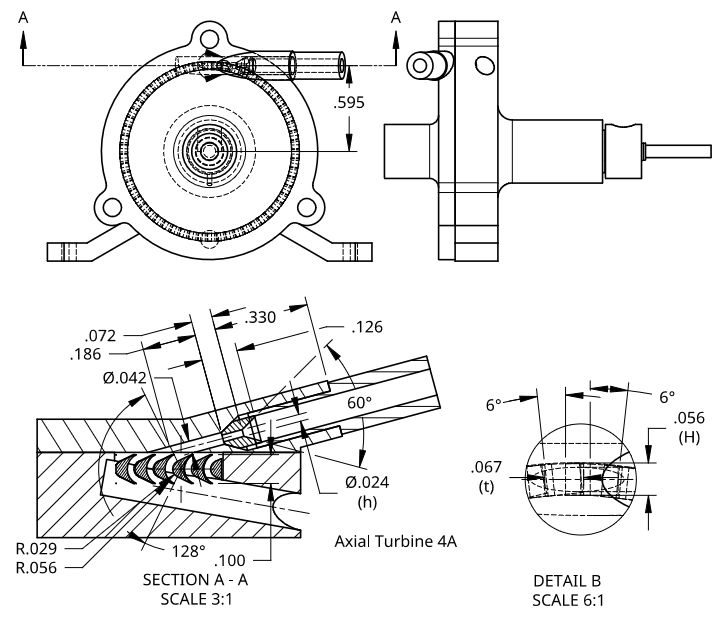
                    I would like to find out why Tangential Turbine 5B with the overlapping pockets almost matched the performance of Axial Turbine 4A with the traditional impulse blades. I based the design of Tangential Turbine 5B on the guidelines given by Dr. Balje in his report ‘A STUDY OF HIGH ENERGY LEVEL, LOW POWER OUTPUT TURBINES’ made in 1958. The rotor used in Axial Turbine 4A was made by Mike Tilby and based on later guidelines that match or exceed the guidelines given by Dr. Balje. I made the following drawings that show the details needed to compare these turbines. Dr. Balje compared the performance of Axial Impulse turbines with Terry turbines that are tangential flow but with blades. His report showed that the Terry turbine could match the performance of Axial Turbines with single nozzles and a small number of blades running at low speeds. I used the guidelines given for the Terry turbines for the design of my tangential turbines and have found that my overlapping pockets performed better than the non-overlapping pockets used by Stumpf turbines. I have not found anything showing the use of overlapping pockets although I doubt I’m the first to try this. You can see on the following drawings that the size of these turbines are almost the same and the energy available to the turbines shown in the following portion of the test sheet on the 23/01/2023 Post is also fairly close. at4a details.jpgtt5b details.jpg

                    turbine test results 51.jpg

                    #638092
                    Turbine Guy
                    Participant
                      @turbineguy

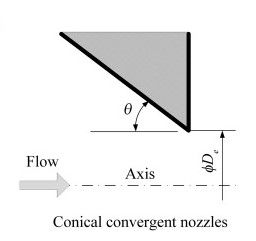
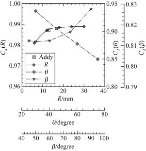
                      The first item I looked at for comparing the performance of Axial Turbine 4A with Tangential Turbine 5B is the nozzle efficiency. Both of these turbines have a 60 degree included angle at the nozzle entrance. The flow coefficient shown in the following chart that was copied from ‘Nozzle geometry variations on the discharge coefficient’ by M.M.A. Alam, T. Setoguchi, S. Matsuo, and H.D. Kim made in November 2015 shows a discharge coefficient of approximately 0.93 for a conical convergent nozzle with 30 degree per side as shown in the following drawing. That flow coefficient would apply for a nozzle with a very short throat length. Axial Turbine 4A has a relatively long nozzle throat length of 0.222” as shown in the drawing of the last post resulting in an estimated 1.7 psi pressure drop reducing the nozzle discharge coefficient to approximately 0.80. This shows the importance of keeping this throat length as short as possible. Tangential Turbine 5B has a nozzle throat length of 0.113” as shown on the drawing of the last post resulting in an estimated 0.6 psi pressure drop reducing the nozzle discharge coefficient to approximately 0.88. Both of these turbines nozzles have a spouting velocity close to sonic velocity so the losses due to expanding to a supersonic velocity are negligible.

                      conical convergent.jpg

                      discharge coefficent.jpg

                      #638559
                      Turbine Guy
                      Participant
                        @turbineguy

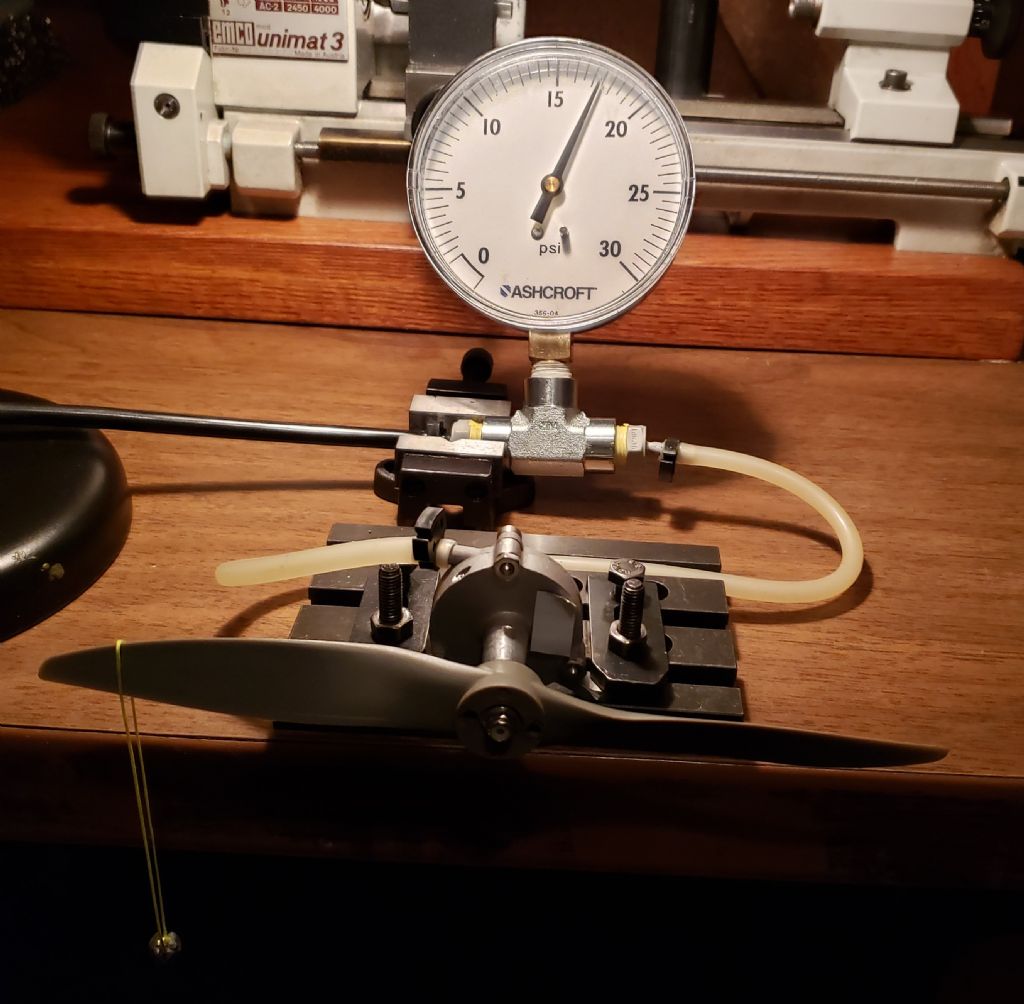
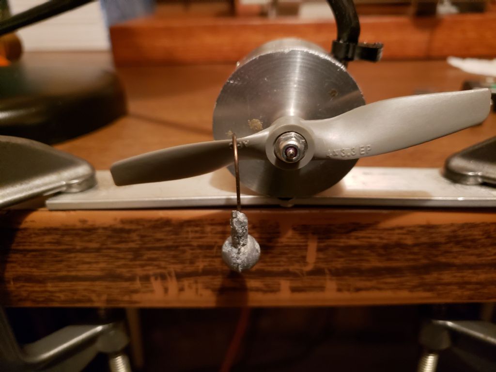
                        The next item I reviewed for comparing the performance of Axial Turbine 4A with Tangential Turbine 5B is the rotor velocity coefficient. I used the method described in the 21/12/2019 Post to determine the stall torque and the equations shown in that post to determine the rotor velocity coefficient. I made some improvements to the test setup. The first was to use a lighter weight at a longer distance as shown in the following photos. This reduces the error in measurement of the distance from the center of the turbine to the point the weight is attached. The second improvement was to use thin string to hold the weight. This allows the whole length of the load to be close to inline. The weights were the only thing keeping the turbines from spinning in both these pictures even though they were at full test pressure. I use propellers for the lever arms since they are balanced in weight each side. I made work sheets to tabulate the results that I will shown in the next post.

                        stall torque at4a.jpg

                        Torque Test

                        #638664
                        Turbine Guy
                        Participant
                          @turbineguy

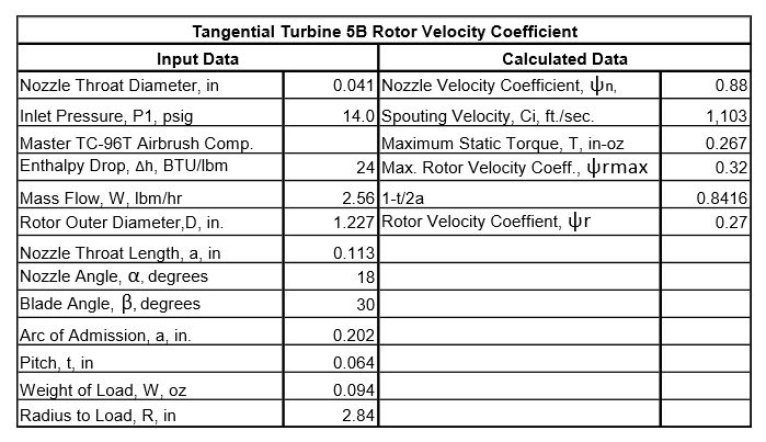
                          The air pressure used in the test of Axial Turbine 4A described in the last post was the same as shown in the following table. The weight of the load used was 0.094 oz. The radius to the load was 3.32” so the maximum static torque was 0.312 in-oz. I did the same test with Tangential Turbine 5B with the same weight and using the pressure shown in the following table. The radius to the load was 2.84” so the maximum static torque was 0.267 in-oz. This large difference in maximum static torque surprised me since these turbines spun the GWS EP 2508 propeller to the same speed of 28,000 rpm. I ran both turbines with the APC 8×6 propeller I used for the static test and they both had a maximum speed of approximately 1200 rpm. Both turbines ran both the large and small propellers at the same maximum speeds even though they had a relatively large difference in maximum static torque. I will try to explain in the next posts how this could happen.

                          turbine test results 47.jpg

                          #638825
                          Turbine Guy
                          Participant
                            @turbineguy

                            I made the following spreadsheets to find the rotor velocity coefficients. In the spreadsheets I used the methods given by Dr. Balje in his report ‘A STUDY OF HIGH ENERGY LEVEL, LOW POWER OUTPUT TURBINES’ made in 1958 for finding the average rotor velocity coefficients. As you can see from the spreadsheets the average rotor velocity coefficients are dependent on the number of blades or pockets covered by the nozzle. The arc of admission, a, of Radial Turbine 5B is approximately 1.5 times as large as that of Axial Turbine 4A. This results in the average rotor velocity coefficient being much closer to the maximum rotor velocity coefficient. Even with this advantage, Tangential Turbine 5B has a much lower average rotor velocity coefficient than Axial Turbine 4A since its maximum rotor velocity coefficient is so much larger. This shows that the traditional axial turbine rotor is quite a bit higher in efficiency than the open pocket tangential turbine rotor. If you look at drawings shown in the 16/03/2023 post, you can see the incidence of the flow entering the blades is much less for Axial Turbine 4A. Also the blades and close clearance on the OD force the flow through a constant area closed on all sides. This keeps the flow from expanding to a lower velocity as it passes thru the blades. The open pockets allow this expansion, and the overlapping pockets have a much higher gap between the OD and housing bore in the center of the pockets so allow more leakage. I will try in the next posts to show how with this large advantage in rotor efficiency, Axial Turbine 4A could only turn the same size propellers the same maximum speed as Tangential Turbine 5B.

                            at4a rvc.jpg

                            tt5b rvc.jpg

                            #638855
                            Turbine Guy
                            Participant
                              @turbineguy

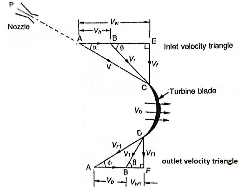
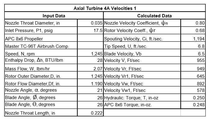
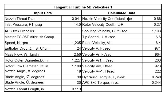
                              I made the following spreadsheets to calculate the hydraulic torque using the velocities found from a typical velocity diagram like shown below. I coded the velocities in the spreadsheets to match the velocity diagram. The propeller used for the test data was the largest propeller I have that had performance data down to speeds as low as 1,000 rpm. I thought that finding the torque at this low of a speed should be close to the stall torque since the rotational losses would be almost negligible. The hydraulic torque is determined by the entrance velocity in the rotor movement direction, Vw, and the exit velocity in the rotor movement direction, Vw1. As you can see from the spreadsheets, Axial Turbine 4A has a much lower Vw than Tangential Turbine 5B, but a much higher Vw1 so the net result is almost the same torque. These spreadsheets show the importance of the velocity coefficients and how they effect the torque. I will use similar spreadsheets in the next post to illustrate  their effect at higher speed using the GWS EP 2508 propeller.

                              velocity diagram 1.jpg

                              at4a velocities 1.jpg

                              tt5b velocities 1.jpg

                              Edited By Turbine Guy on 23/03/2023 17:45:35

                              #638863
                              Turbine Guy
                              Participant
                                @turbineguy

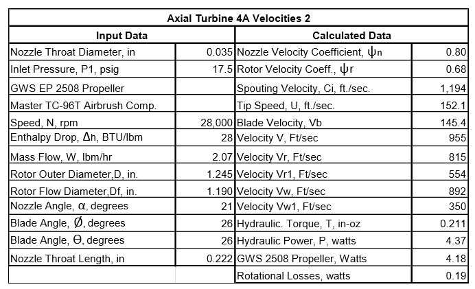
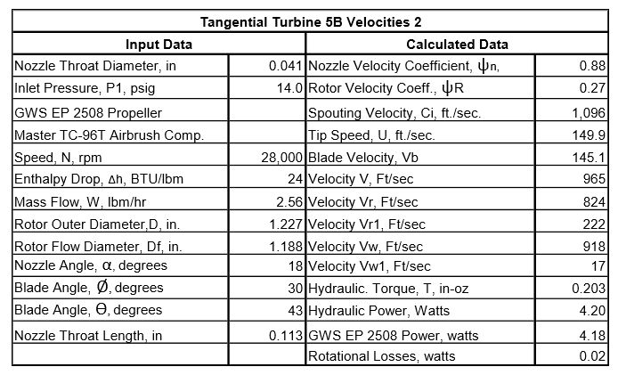
                                The following spreadsheets, similar to the ones in the last post, show the effect of using a smaller propeller running at a higher speed of 28,000 rpm. This speed is high enough to start getting significant rotational losses so the hydraulic power must be larger than the actual power to absorb these losses. The rotational losses are larger with the blades than with the open pockets, but neither was very large at this speed. The most significant reason Tangential Turbine 5B almost matched the performance of Axial Turbine 4A was its better nozzle efficiency due to a much shorter throat length. This difference in throat length was caused by the center drills I use to create the nozzles that I will explain in the next post.

                                at4a velocities 2.jpg

                                tt5b velocities 2.jpg

                                #638870
                                Turbine Guy
                                Participant
                                  @turbineguy

                                  You can see in the following drawings showing the details of Axial Turbine 4A and Tangential Turbine 5B that I tried to get the center drill as close to the housing bore or face of the cover as I could. This is the best tool I have found to make a reasonably efficient nozzle and is only available with a 1/8” OD. It is the large OD that creates the problem. That is why I was excited about using an insert in Tangential Turbine 5C to get the nozzle throat length even shorter and provide a space for the gas to expand before contacting the rotor. I got a test of Tangential Turbine 5C running on steam described the 08/03/2023 post that made a significant improvement, but the insert quit working while running further tests on steam. I had to remove the insert to find what was causing the problem and decided to make a new insert with a smaller bore like I first planned to do. The used tailstock I ordered for my Unimat 3 lathe arrived and is in excellent condition as described by the seller in Ebay. I hope this will solve my problem of drilling the very tiny holes and plan to make a new insert and start testing Tangential Turbine 5C again. If I am able to drill the very small holes again, I will design a new cover for Axial Turbine 4A that will use this concept for what I will call Axial Turbine 4D.axisl turbine 4a.jpgtt5b details.jpg

                                  #639278
                                  Turbine Guy
                                  Participant
                                    @turbineguy

                                    The replacement tailstock did solve the problem of drilling the very tiny holes. I was able to make the insert shown in the following drawings on my first try. I added the insert in Axial Turbine 4A first that was going to be called Axial Turbine 4D. I made a few tests with Axial Turbine 4D and then removed the insert and added it to Tangential Turbine 5C as shown below. The insert performed better in Tangential Turbine 5C so I will use this turbine for the tests with steam that needed the 0.024” nozzle size. I will discuss the performance of the insert running both turbines on air in the next post.

                                    at4d details.jpg

                                    tt5c details.jpg

                                    #639355
                                    Mike Tilby
                                    Participant
                                      @miketilby23489

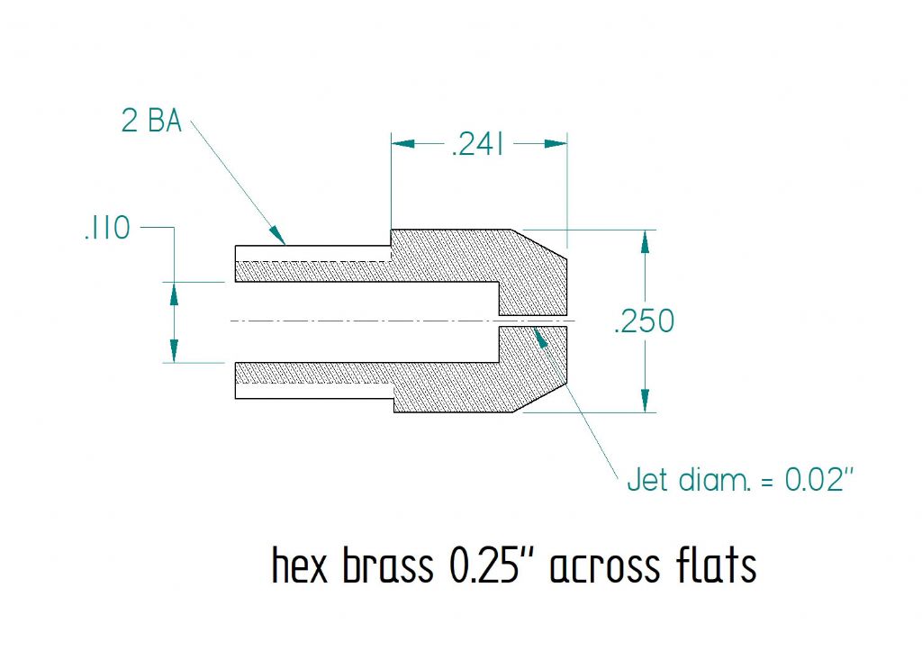
                                      My own experience of making jets for a model butane burner supports your conclusion about the importance of keeping the throat length very short. The bore in a series of jets that I made was 0.02” diam. The length of the bore (i.e. the thickness of the nozzle end, as shown in the drawing below) was varied from 0.109”, 0.05” and 0.024”. (Measurement of actual thickness was by inserting inside the jet body a small rod of known length and measuring the overall length of rod and jet). There was a very impressive improvement in performance of the burner at each stage of shortening.

                                      As you know, in many turbines the nozzles have to be curved and text books that I’ve read advise that a convergent nozzle should narrow down over a short distance and have a short straight parallel section at the exit to help steam leave at the desired angle. The length of this section should be about the same as its width. For a straight nozzle like yours I imagine that length could be even shorter. So I bet the reducing the bore length to even less than 0.067” would be advantageous, if that could be done.

                                      My own nozzles have a construction that allows the curved shape. The outlet is 0.027” wide and they have a straight parallel exit section 0.027” long, as shown in the drawing below. (The only trouble is I’ve not yet reached the stage of using them to turn a rotor).

                                      nozzle design for model turbinejet for model butane burner

                                      #639378
                                      Werner Jeggli
                                      Participant
                                        @wernerjeggli14222

                                        Hello Mike,

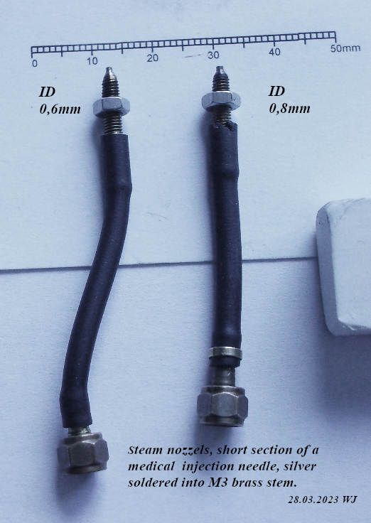
                                        Why don't you use sections of medical injection needles. There is a large variety of sizes. To doctors, they are consumer items and I get them free of charge!

                                        nozzles.jpg

                                        #639395
                                        Mike Tilby
                                        Participant
                                          @miketilby23489

                                          Hello Werner

                                          My design is based on my (possibly erroneous) understanding of how turbines should ideally be designed, but I cannot be sure to what extent the following is correct for a miniature turbine. Hopefully I’ll find out one day when I eventually get a working machine.

                                          My nozzles need to fit in the narrow diaphragm that separates the stages of what I hope will one day be a multi-stage turbine. Also the outlets of the nozzles need to be at a small angle (18 degrees) to the plane of the rotor. Drilling holes at such a small angle would be very difficult and would not fit within the circumference of the diaphragm. As in full-size turbines of this type, the nozzles have to be curved so that steam entering from the previous stage has its direction of flow changed to give the correct exit angle. Another aspect is that, for best efficiency, the text books say that a convergent nozzle should taper down by a smoothly curved shape over a short distance to the exit width. This minimises losses due to friction and eddy formation. Frictional losses are greatest at the highest steam velocity and that is attained at the outlet. Also, frictional loss is highest at the narrowest part of a nozzle which is also at the exit of a convergent nozzle. Therefore the final and narrowest part should be kept just short enough to sufficiently control the direction of the steam. Further back in the nozzle the steam has not yet expanded /accelerated so much and nozzle width is greater. These factors all mean that steam velocities at those earlier parts of a nozzle are much lower and so friction is reduced. With my design I have almost full control of the nozzle profile. Another reason for favouring my nozzle design is that the steam path is rectangular and so matches the gaps between the rotor blades. This means that the steam should fill the gaps whereas steam jets from circular nozzles would not fill the corners. I doubt this aspect has much impact on a miniature turbine but I think it was considered important for full-size turbines.

                                          Mike

                                          #639405
                                          Turbine Guy
                                          Participant
                                            @turbineguy

                                            Hi Mike and Werner,

                                            Thanks for breathing a little life into this thread. I have very little time this morning, so I will be very brief. I totally agree with Mikes comments on his type of nozzle and believe that it would produce the highest efficiency for subsonic to sonic flows and is the most used by full size turbines for these conditions. The round nozzles with converging and diverging sections seem to be preferred for the supersonic flows. I'm not sure which type would be best for a converging only nozzle expanding to supersonic velocities outside the nozzle. I agree with Werner that it is a lot easier to make an insert from injection needles or surgical tubing than drilling a tiny hole.

                                            Thanks for the comments,

                                            Byron

                                            #639560
                                            Turbine Guy
                                            Participant
                                              @turbineguy

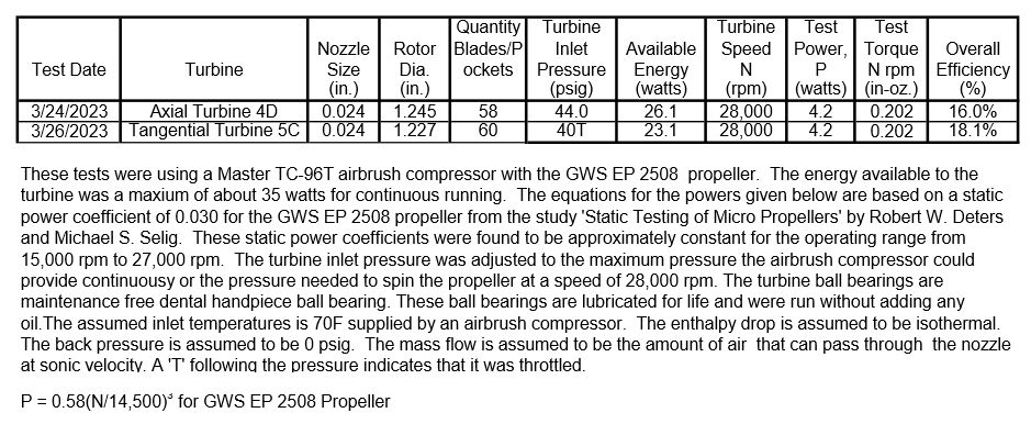
                                              The following test sheet shows the performance of Axial Turbine 4D and Tangential Turbine 5C running on air I said I was going to show after the 27/03/2023 post that also included the following drawings. I will look at the reasons for this performance in the next posts.

                                              at4d details.jpg

                                              tt5c details.jpgturbine test results 52.jpg

                                              #639569
                                              Turbine Guy
                                              Participant
                                                @turbineguy

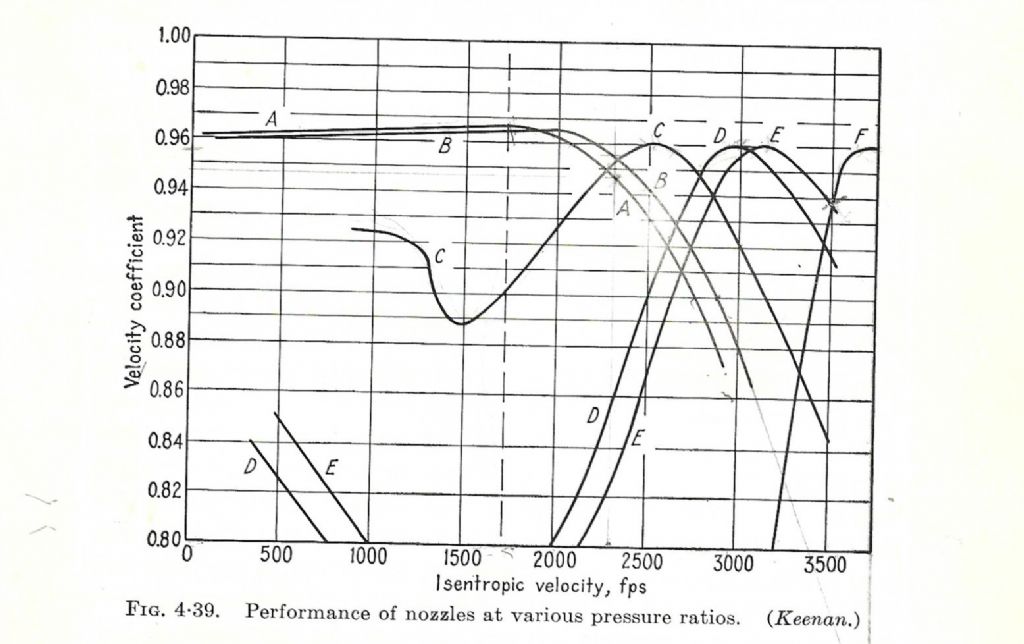
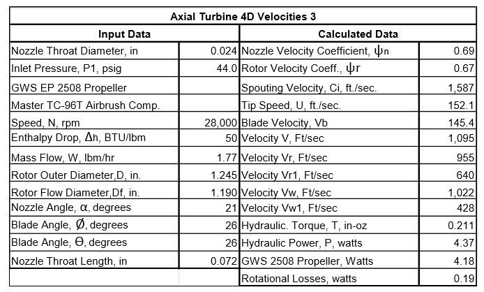
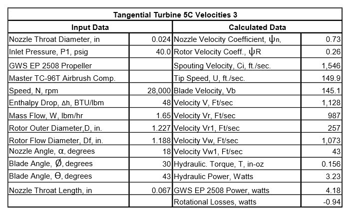
                                                I estimated the nozzle velocity coefficient of Axial Turbine 4D to be approximately 0.69 and 0.73 for Tangential Turbine 5C for the tests shown in the last post. These velocity coefficients were determined by starting with the velocity coefficient of 0.93 for the conical nozzle as explained in the 17/03/2023 post then finding the reduction for the pressure drop due to friction. The reduction due to pressure drop was 0.94 for both turbines since they had the same nozzle throat length. This reduced the nozzle velocity coefficient to 0.87. I then found the reduction for expanding to supersonic velocities with a converging only nozzle shown in the following diagram as line A. In the tests shown in the previous post, the Mach number for Axial Turbine 4D was 1.47 and for Tangential Turbine 5C was 1.43. The reduction for expanding supersonic is approximately 0.97 for both turbines when rounded to two decimal places. This reduces the nozzle velocity coefficient to 0.84 for both turbines. The last reduction was for the distance between the nozzle outlet to the rotor. This was 0.186” for Axial Turbine 4D and 0.113” for Tangential Turbine 5C as shown on the two drawings of the last post. The reduction in nozzle velocity coefficient for this was 0.82 for Axial Turbine 4D and 0.87 for Tangential Turbine 5C. This reduced the nozzle velocity coefficient to 0.69 for Axial Turbine 4D and to .73 for Tangential Turbine 5C as stated at the first of this post. The reduction in rotor velocity coefficient for supersonic velocity was 0.98 for both turbines. The rotor velocity coefficient found from the static torque test explained in the 23/03/2023 post were 0.68 for Axial Turbine 4A and 0.27 for Tangential Turbine 5B. Neither of these turbines had the insert and the discharge velocity of the nozzles were approximately sonic, so using the correction for supersonic velocities reduces the rotor velocity coefficient to 0.67 for Axial Turbine 4D and to 0.26 for Tangential Turbine 5C. I will show in the next post how the test results in the last post compare with the velocity diagrams like shown in the 23/03/2023 post.
                                                Supersonic Nozzles Chart

                                                Edited By Turbine Guy on 29/03/2023 21:20:09

                                                #639614
                                                Turbine Guy
                                                Participant
                                                  @turbineguy

                                                  The following spreadsheets show the results of Axial Turbine 4D and Tangential Turbine 5C using the rotor velocity coefficients and nozzle velocity coefficient shown in the last post. These values worked well for Axial Turbine 4D but not for Tangential Turbine 5C. The rotor velocity coefficient found by the stall torque in the 23/03/2023 post appears to be quite a bit low. I will see if I can find the error.

                                                  at4d velocities 3.jpg

                                                  tt5c velocities 3.jpg

                                                  #639749
                                                  Turbine Guy
                                                  Participant
                                                    @turbineguy

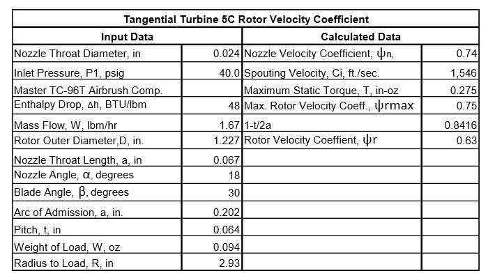
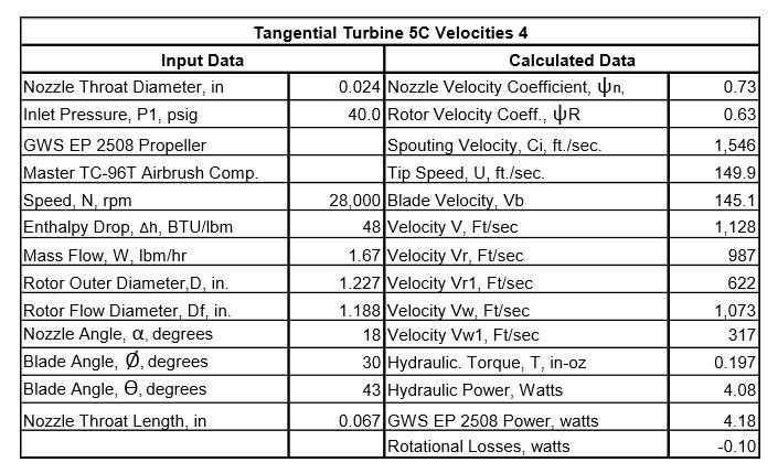
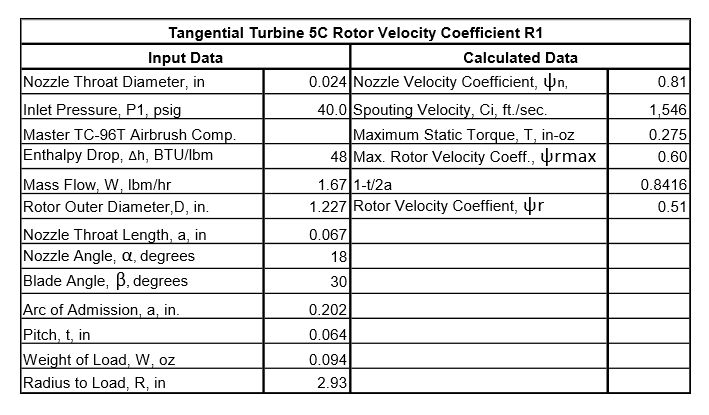
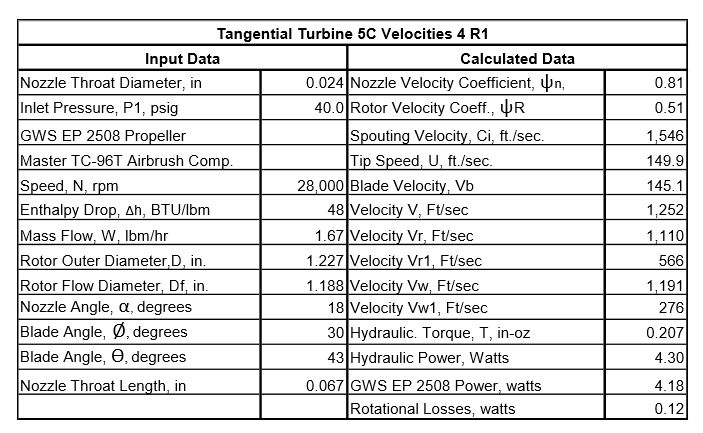
                                                    I couldn’t find the reason for the velocity coefficients only working for Axial Turbine 4D as discussed in the last post, so I made a stall torque test for Tangential Turbine 5C like described in the 21/03/2023 post. The air pressure used in the test of Tangential Turbine 5C was the same as shown in the last post. The weight of the load used was 0.094 oz. The radius to the load was 2.93” so the maximum static torque was 0.275 in-oz. I used the nozzle velocity coefficient determined in the 29/03/2023 post in the following spreadsheet to find the rotor velocity coefficient. This rotor velocity coefficient is more like I expected and works better as shown in the following velocities spreadsheet.

                                                    tt5c rvc.jpg

                                                    tt5c velocities 4.jpg

                                                    #639885
                                                    Turbine Guy
                                                    Participant
                                                      @turbineguy

                                                      I found an error in the nozzle velocity coefficient for Tangential Turbine 5C I described in the 29/03/2023 Post. The correction for the distance from the nozzle to the rotor should have been 0.95 instead of 0.87. This changed the nozzle velocity coefficient from 0.73 to 0.81 and resulted in the rotor velocity coefficient shown in the 31/03/2023 post changing from 0.63 to 0.51. The following spreadsheets show the effect of this change. The estimated hydraulic power at 28,000 rpm is greater than the actual power like it must be.

                                                      tt5c rvc r1.jpg

                                                      tt5c velocities 4 r1.jpg

                                                    Viewing 25 posts - 451 through 475 (of 583 total)
                                                    • Please log in to reply to this topic. Registering is free and easy using the links on the menu at the top of this page.

                                                    Advert

                                                    Latest Replies

                                                    Home Forums Stationary engines Topics

                                                    Viewing 25 topics - 1 through 25 (of 25 total)
                                                    Viewing 25 topics - 1 through 25 (of 25 total)

                                                    View full reply list.

                                                    Advert

                                                    Newsletter Sign-up