Model Turbines

Advert

Model Turbines

Home Forums Stationary engines Model Turbines

Viewing 25 posts - 426 through 450 (of 583 total)
  • Author
    Posts
  • #622118
    Turbine Guy
    Participant
      @turbineguy
      Posted by Roger Best on 21/11/2022 16:49:59:

      We are getting big efficiency numbers now. Well done Turbine Guy.

      It's been a long slow process, thanks for the encouragement.

      Advert
      #622342
      Turbine Guy
      Participant
        @turbineguy

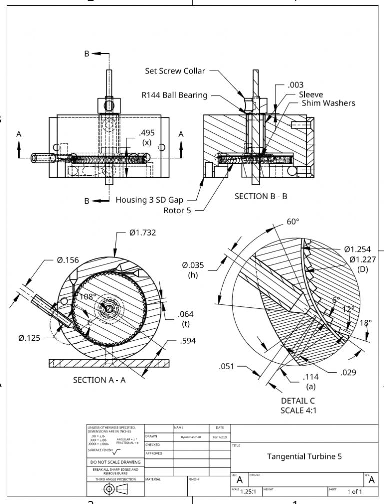
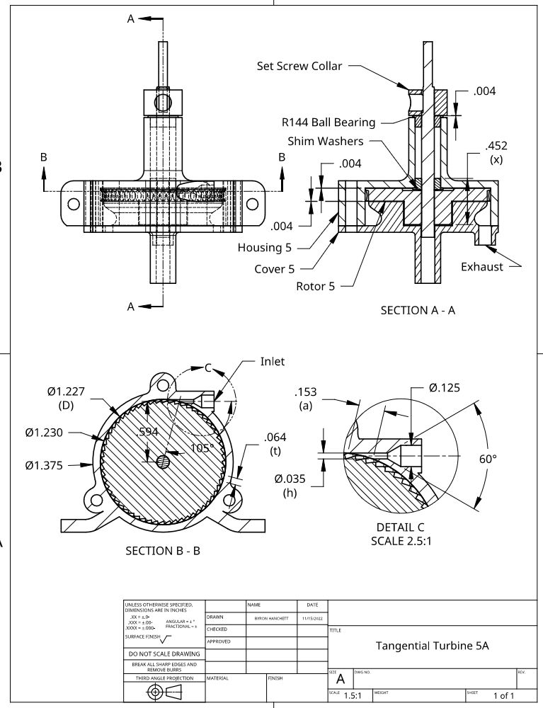
        The first improvement I want to try on Tangential Turbine 5 is increasing the overlap as discussed in the 21/11/2022 posts. The overlap of the nozzles in tangential turbines is maximum when the nozzle outer edge is tangent to the housing bore for the rotor. When this bore was increased on Housing 3 SD to add the gap, it moved the outer edge of the nozzle away from the housing bore decreasing the overlap (a) from 0.125” to the existing 0.114” shown on the following Tangential Turbine 5 drawing. I thought that this decrease in overlap would reduce the performance with low energy levels, so I ran tests before and after the bore size was increased as discussed in the 24/05/2021 Posts. These tests and those I have made with the axial turbines all show the distance from the nozzle to the rotor should be kept as small as possible for low energy levels. Making a new housing with a smaller bore will reduce the distance from the nozzle to the rotor and increase the overlap. This change should improve the performance of Tangential Turbine 5 at low energy levels. Housing 3 SC Gap will still be the best for high energy levels. The new housing should also be designed to allow tight clearances to be used on both faces of the rotor as discussed in the 21/11/2022 posts. The next post will show the preliminary drawing for Tangential Turbine 5A that will have a new printed aluminum housing and cover to increase the overlap and allow tight clearances on both faces of the rotor.

        tangential turbine 5 r4.jpg

        #622343
        Turbine Guy
        Participant
          @turbineguy

          tangential turbine 5a.jpg

          #624570
          Turbine Guy
          Participant
            @turbineguy

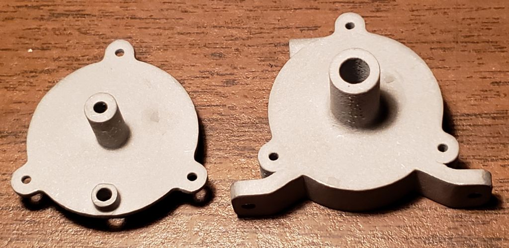
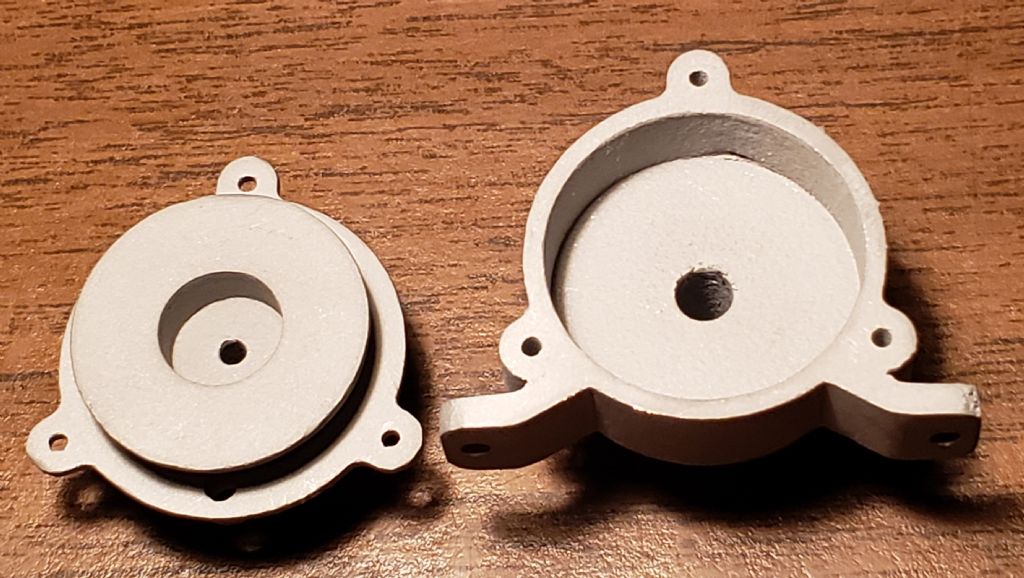
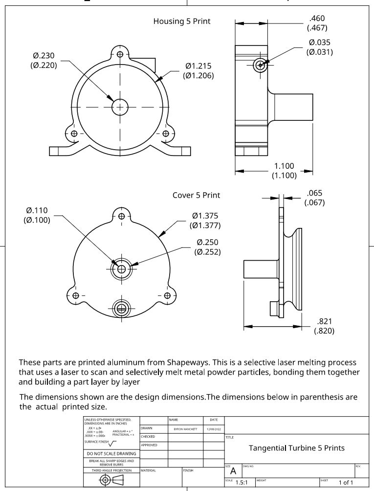
            I received the printed aluminum parts from Shapeways for Housing 5 and Cover 5 shown in the drawing of the last post. The following photos show the front and back of these parts. The design dimensions and actual printed dimensions will be shown in the next post.

            tt 5 prints photo 1.jpg

            tt 5 prints photo 2.jpg

            #624571
            Turbine Guy
            Participant
              @turbineguy

              The following drawing shows the design dimensions and actual printed dimensions for Housing 5 and Cover 5 of Tangential Turbine 5A described in the 23/11/2022 posts.

              tt 5 prints.jpg

              #625203
              Turbine Guy
              Participant
                @turbineguy

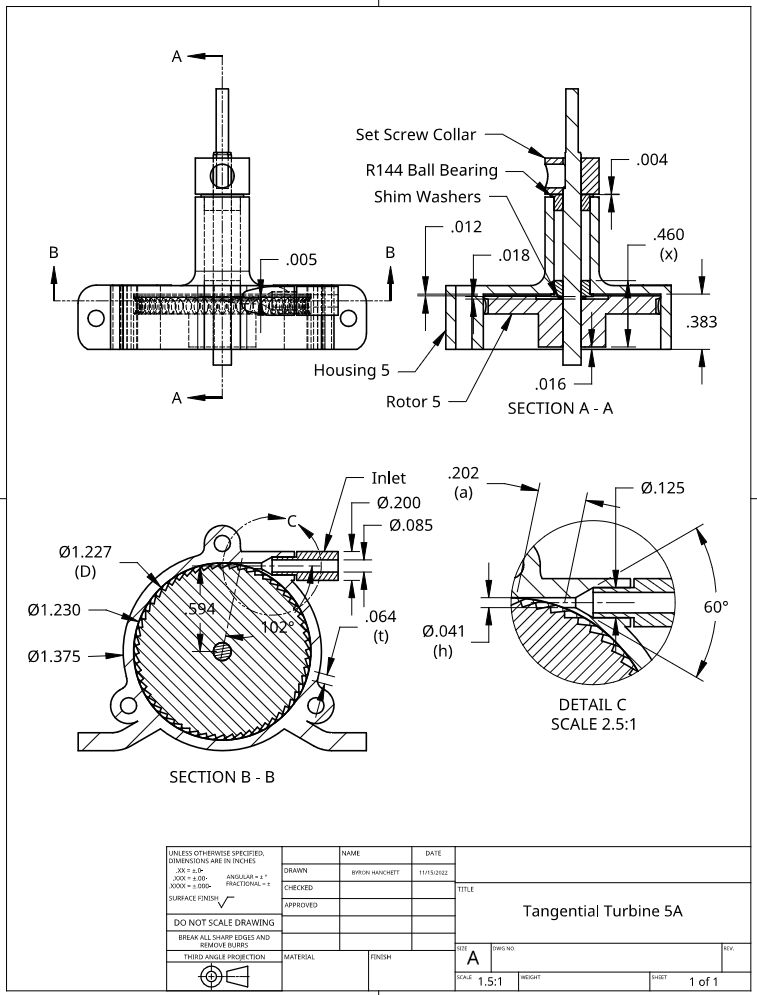
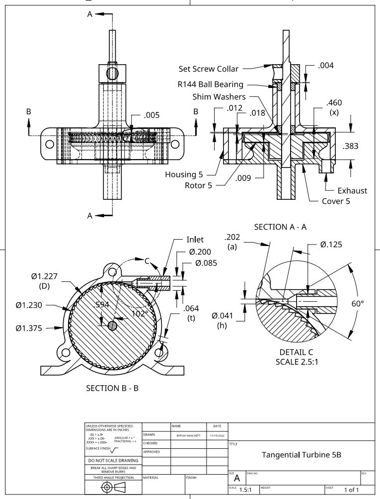
                I decided to add two new versions of Tangential Turbine 5. The first version will be Tangential Turbine 5A and will be the same as Tangential Turbine 5 shown in the 23/11/2022 post except will replace Housing 3 SD Gap with Housing 5. This will compare the performance of the housings with almost everything else the same. The first revision to the drawing for Tangential Turbine 5A shown below removed the cover, added the dimensions after machining, and showed the placement of the rotor that gave the best performance. I planned to keep the nozzle size 0.035” but had to open it to 0.041”. The second version of Tangential Turbine 5 will be called Tangential Turbine 5B and will be the same as Tangential Turbine 5A except will include Cover 5. Tangential Turbine 5B will be discussed after I finish the first machining of Cover 5. I will run Tangential Turbine 5A with the rotor positioned as shown in the following drawing and then run Tangential Turbine 5B immediately after. This will keep everything the same except the addition of Cover 5. The next post will shows photos of Tangential Turbine 5A.

                tangential turbine 5a r1.jpg

                #625204
                Turbine Guy
                Participant
                  @turbineguy

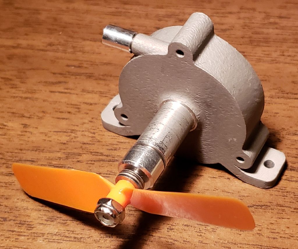
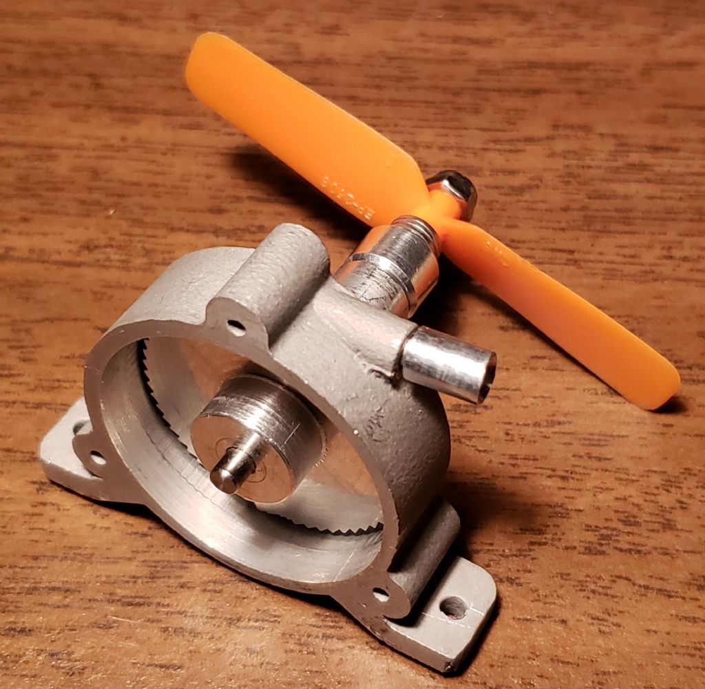
                  The following are photos of Tangential Turbine 5A with the rotor positioned as shown in the drawing included in the last post.tt 5a photo 1.jpg

                  tt 5a photo 2.jpg

                  #625437
                  Turbine Guy
                  Participant
                    @turbineguy

                    I finished the machining on Cover 5 for the first test of Tangential Turbine 5B. The following drawing shows the placement of the rotor and the corresponding clearances. I needed a clearance of 0.009" between the outer face of the rotor and Cover 5 and a clearance of 0.012" between the inner face or the rotor and Housing 5. These clearances had to be this large to avoid contact due to the loose clearances of the dental ball bearings. The next posts will show some photos and the first test results.

                    tangential turbine 5b.jpg

                    #625439
                    Turbine Guy
                    Participant
                      @turbineguy

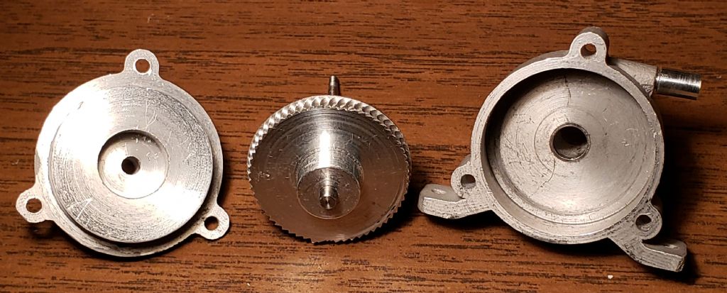
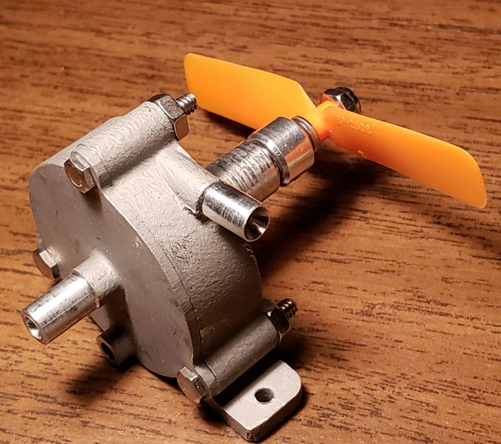
                      The following photos show the parts and assembly of Tangential Turbine 5B.

                      tt 5b parts.jpg

                      tt 5b photo 1.jpg

                      #625442
                      Turbine Guy
                      Participant
                        @turbineguy

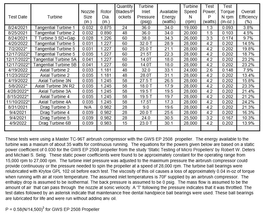
                        The following test sheet is the first test of Tangential Turbine 5A and Tangential Turbine 5B. The test of Tangential Turbine 5B was run immediately after the test of Tangential Turbine 5A so the only difference was adding Cover 5. The efficiency was the same with or without Cover 5. the 0.009" clearance between Cover 5 and the outer face of the rotor improved the efficiency enough to compensate for the pressure drop added by the cover.

                        turbine test results 44.jpg

                        #628370
                        Turbine Guy
                        Participant
                          @turbineguy

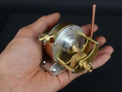
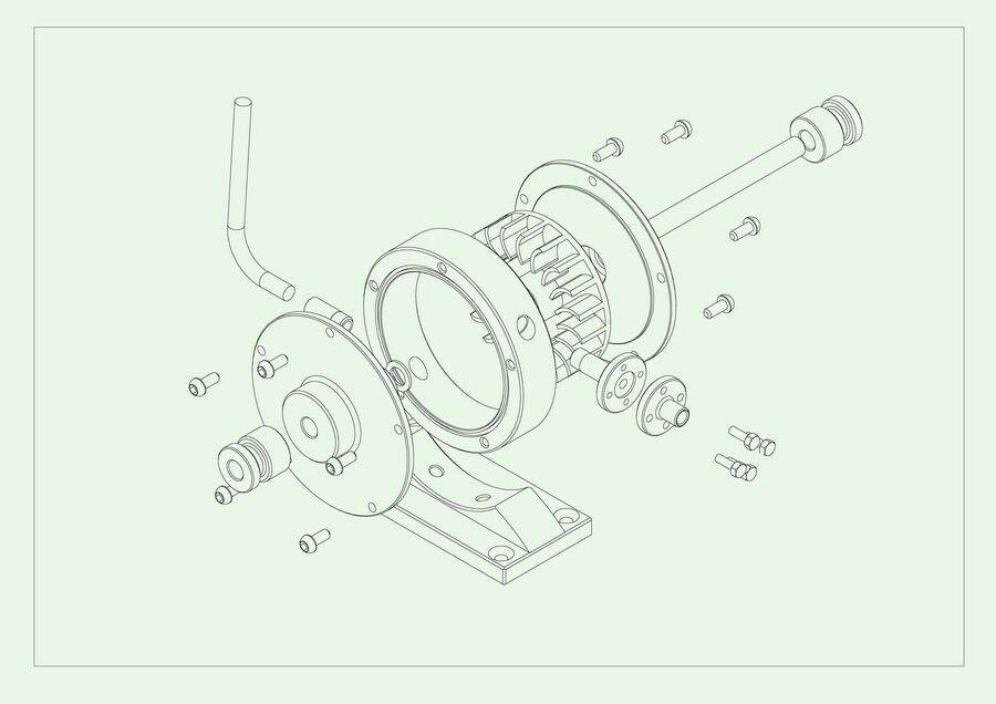
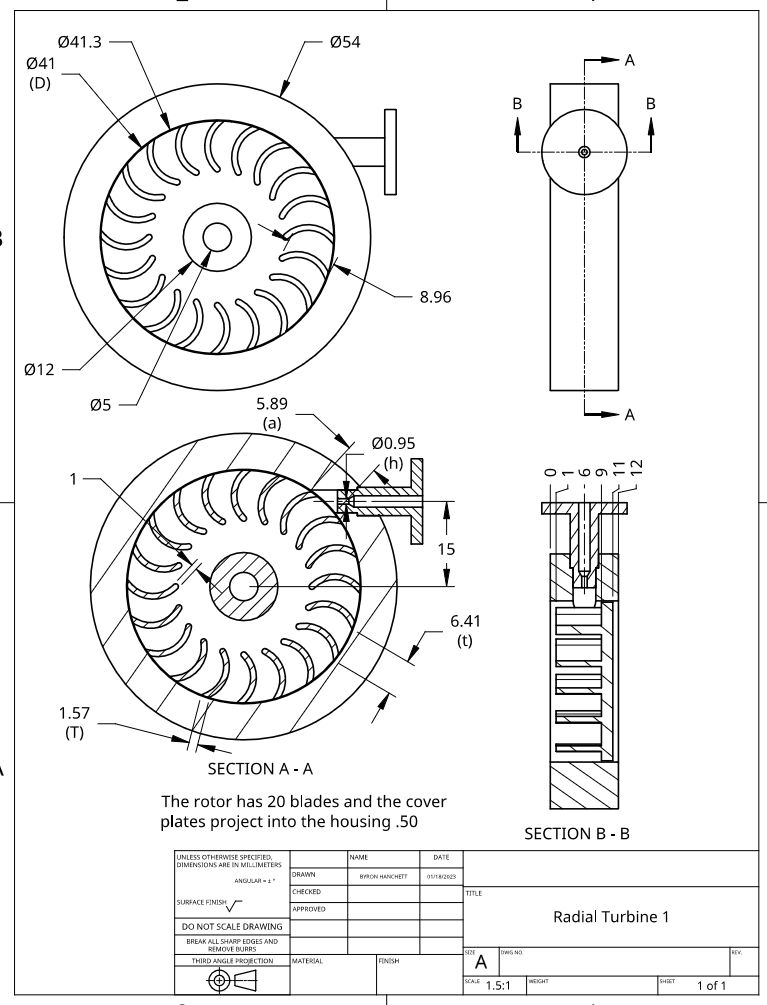
                          I want to see how the model turbines I have built compare with ones that can be purchased. The Radial Turbine Link describes the Radial Turbine I just purchased shown in the photo below. The radial turbines seem to be the type most available and I have not tested this kind of turbine. I picked this particular model since it appeared to be a good design that seems to have ball bearings on each side of the rotor as shown in the drawing below. It also includes a speed reducer which is something I have also wanted to test. I created a Radial Turbine 1 folder and will update it as I get more information. This model is coming from China so It will be about a month before I receive it.

                          radial turbine photo 2.jpg

                          radial turbine 1.jpg

                          Edited By Turbine Guy on 09/01/2023 20:55:37

                          Edited By Turbine Guy on 09/01/2023 20:58:27

                          #628666
                          Turbine Guy
                          Participant
                            @turbineguy

                            Werner Jeggli saw the last post and thought he had seen this type of turbine used for driving a train. He sent me This Link. I asked him if he could get me a little more information about the turbine. He contacted Michael Fueg who created the video and the model train shown in it. Michael Emailed me some information about the train. He created this train to see if the turbine he bought was suitable to drive a train, so it was kept as simple as possible. It turned out that the turbine he used was the same as shown in the last post except for using a two-stage gear reduction instead of the single stage used on mine. Michael sent me this Second Link showing the train running and closeups of some of the details. As you can see from the videos, the turbine drives the train quite well. The following photo shows the details of the turbine attached to the frame.

                            fueg photo 2.jpg

                            Edited By Turbine Guy on 11/01/2023 16:30:20

                            Edited By Turbine Guy on 11/01/2023 16:39:52

                            Edited By Turbine Guy on 11/01/2023 16:52:39

                            #628949
                            Turbine Guy
                            Participant
                              @turbineguy

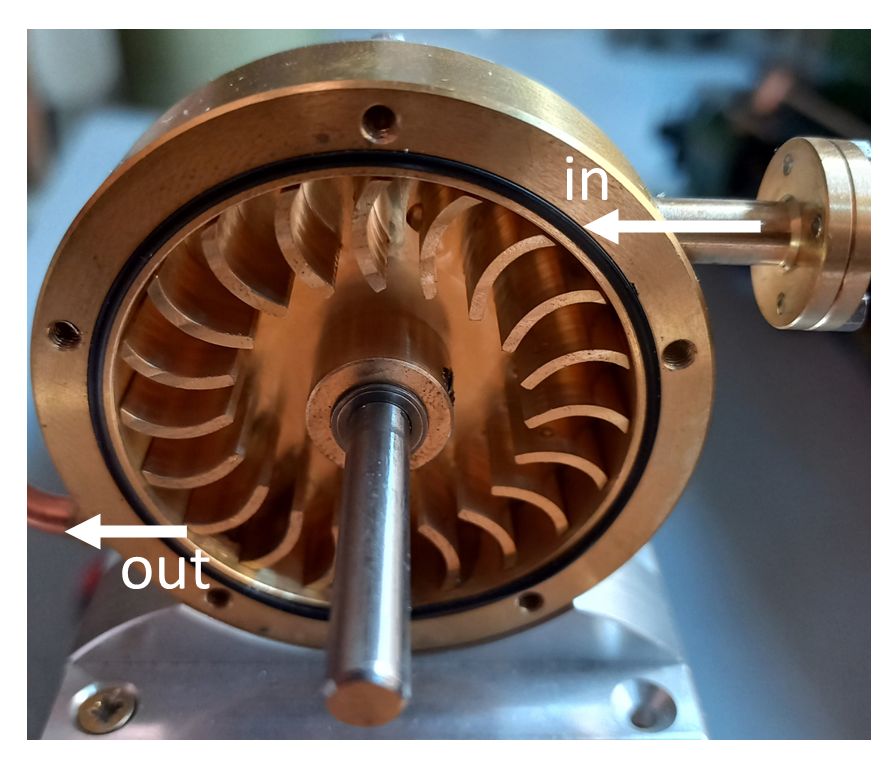
                              Michael Fueg described his turbine as a cross-flow type like the figure shown below and the photo of his turbine with one cover removed. This would be a velocity staged turbine since the gas passes through one set of blades before entering a second set of blades. Most of the information I have found is for hydraulic cross-flow turbines. The wind cross-flow turbines are used to generate power where a compact size is needed. It will be very interesting to see how the performance of this type of turbine compares with the ones I have already tested. Since Michaels turbine was successful powering a train, my turbine should be powerful enough to get good results from one of the propellers I use for testing.

                              cross flow diagram.jpgfueg photo 3.jpg

                              #630513
                              Turbine Guy
                              Participant
                                @turbineguy

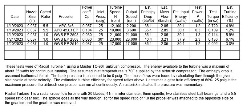
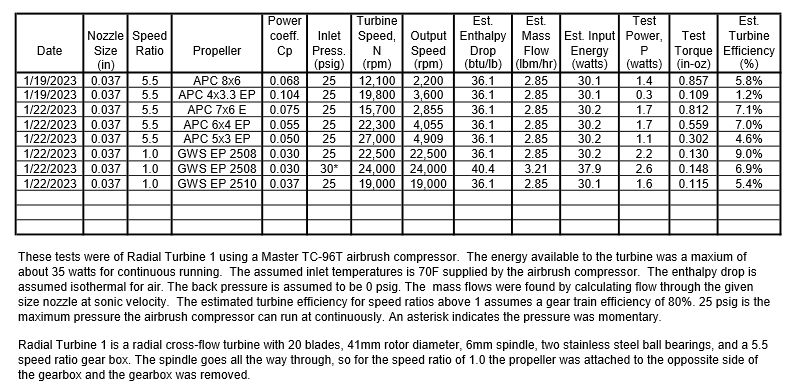
                                I received Radial Turbine 1 described in the last posts. I made my first tests without changing anything, so it was as received. After trying different propellers on the gearbox output shaft, I removed the gearbox and mounted propellers directly on the turbine output shaft. All these tests shown in the following test sheet were done without adding any lubrication. I reinstalled the gearbox and made sure that my test results run with it were repeatable. I then tried adding oil to the gears and bearings of the gearbox and repeated the tests that used the gearbox. The results were the same. The oil I used didn’t make any difference. I welcome any suggestions of what type of oil should be used on the gearbox. I have not opened up the turbine, so I don’t know what its ball bearings look like. I couldn’t tell what the bearings used in the gearbox were. They could be some kind of bushing or ball bearing. I need to disassemble the gearbox far enough to look at the bearings with a magnifier. All the tests but one were done with the maximum pressure the airbrush compressor can sustain continuously to be consistent with the other turbine test results. The one test I did at 30 psig was to confirm my impression that this turbine needs more energy to perform at its best. I don’t think the propellers I tried with the gearbox are a good match for my airbrush compressor and this turbine. I ordered a few propellers and I will try to get a better combination.turbine test results 45.jpg

                                #630715
                                Turbine Guy
                                Participant
                                  @turbineguy

                                  I received the propellers and ran some further tests with Radial Turbine 1 shown in the following test sheet. Part way through the tests, I noticed the inlet flange on the turbine housing rotated when I moved the air hose. I took the air hose off and found that the fitting was screwed into the housing. I reinstalled the fitting with Loctite 290 to lock it in place and seal it. I ran the last test performed before I found the loose fitting and the power increased. Since I didn't know when the fitting became loose, I ran all the other tests again and updated the performance. The APC 7×6 E propeller gave the best performance using the gear speed reducer and the power and efficiency stayed almost the same for turbine speeds from 16,000 rpm to 22,000 rpm. Since the turbine speed was almost the same for the run with the APC 6×4 EP propeller using the gear speed reducer and the GWS EP 2508 propeller run with the speed reducer removed, the efficiency of the gear train can be estimated. The power with the speed reducer was 1.7 watts and without the speed reducer was 2.2 watts. The gear train efficiency was approximately 1.7/2.2 = 77%. This is very close to the 80% efficiency I assumed in the test sheet.

                                  turbine test results 46.jpg

                                  #630726
                                  Turbine Guy
                                  Participant
                                    @turbineguy

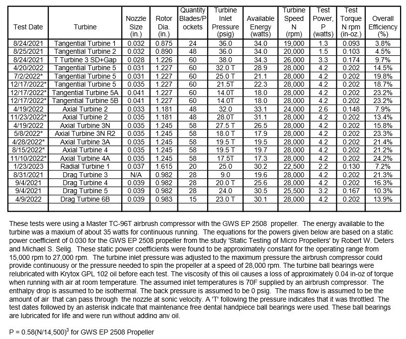
                                    The estimated turbine efficiency for the run with the GWS EP 2508 propeller and 25 psig pressure shown in the last post should be 7.2% like shown in the following test sheet. I found this error when I added this run to the test sheet showing all the other turbines.

                                    I believe the better performance of my best tests with each of the other types of turbines is primarily due to the high rotational losses the radial turbine has with partial admission. The axial impulse turbines have this same problem if the blades get very tall. The blades not being filled by the nozzle act like the blades of a centrifugal compressor drawing the air in at the bottom and forcing the air out the top. Tight clearances on the sides and top of the blades reduce this loss but it still can be significant. turbine test results 47.jpg

                                    #630878
                                    Turbine Guy
                                    Participant
                                      @turbineguy

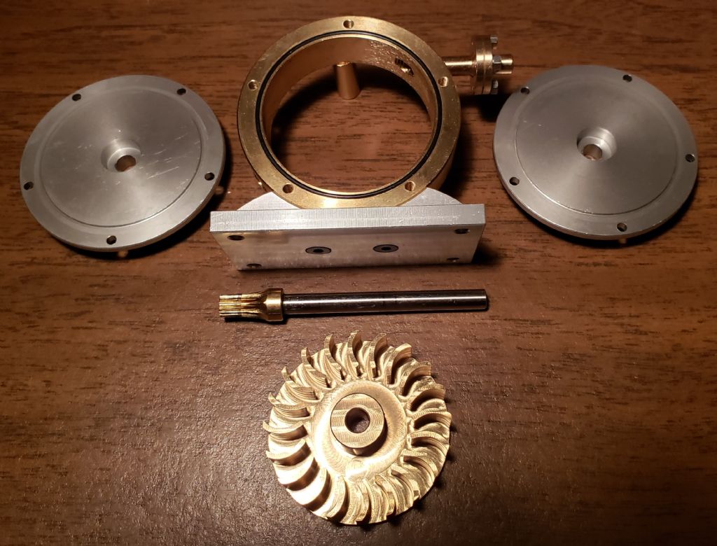
                                      I disassembled Radial Turbine 1 and took some photos and measured some key dimensions. The following photo shows the major parts and the following drawing shows the key dimensions. The turbine ball bearings are 5x10x4 (105-2Z) with shields on both sides. The speed reducer ball bearings are 5x8x2.5 (85-2Z) with a 9x.6 flange and shields on both sides.

                                      rt1 parts.jpg

                                      rt1 dimensions.jpg

                                      #631133
                                      Turbine Guy
                                      Participant
                                        @turbineguy

                                        When I reassembled Radial Turbine 1, it was supplied with three 0.1mm shims and two 0.5mm shims. It required the three 0.1mm shims between the rotor face with the blades and the outer ball bearing to barely clear contact with the outer cover. The two 0.5mm shims between the back side of the rotor and the inner ball bearing removed almost all the play and provided just enough clearance for thermal expansion or contraction. With the shims in this position Radial Turbine 1 repeated the same performance it had before it was taken apart. Although the performance didn’t match the best of the turbines I have tested, it is a very nice model. The machining is very good giving it a pleasant appearance. For someone that just wants a model turbine to run on an airbrush compressor it will run up to speeds that give a nice turbine whine with my smallest airbrush compressor and any of the propellers I used. Because of the high windage losses with the radial blades, it can’t spin fast enough without a load to do any damage even with my largest airbrush compressor. I ran Radial Turbine 1 without a propeller and with my largest airbrush compressor at its maximum output and it reached a top speed of approximately 40,000 rpm. This makes it very safe for running without a load. You must be very careful running with the propellers since they have sharp edges and run at high speeds. I plan on leaving the gear speed reducer off since I only wanted it to test the efficiency of this type of gear speed reducer. This single stage gear speed reducer had an efficiency of approximately 80% as mentioned in the 23/01/2023 post.

                                        #631158
                                        duncan webster 1
                                        Participant
                                          @duncanwebster1

                                          I'm not entirely clear about the bearing shims, but when I worked on high speed gearboxes many years ago we used bearing preload washers to lightly axially load the bearings. This prevented skidding between the balls and race, but allowed for differential expansion as things warmed up.prof Chadfock used a more sophisticated but similar setup in the Quorn

                                          Edited By duncan webster on 27/01/2023 23:00:17

                                          #631205
                                          Turbine Guy
                                          Participant
                                            @turbineguy
                                            Posted by duncan webster on 27/01/2023 22:59:24:

                                            I'm not entirely clear about the bearing shims, but when I worked on high speed gearboxes many years ago we used bearing preload washers to lightly axially load the bearings. This prevented skidding between the balls and race, but allowed for differential expansion as things warmed up.prof Chadfock used a more sophisticated but similar setup in the Quorn

                                            Edited By duncan webster on 27/01/2023 23:00:17

                                            The shim washers I have been using are flat with an ID that is a close fit to the shaft and an OD that is small enough that it has clearance with the outer race of the ball bearing. These were what was used in Radial Turbine 1. My last turbines are using the ball bearings used in the Star high speed dental handpiece. The rotor in this handpiece uses wave washers to accomplish what you described. The wave washers used in the Star handpiece are available at a very low cost and would work in all my turbines using the same bearings. I've noticed some noise that I think is caused by the rotor moving back and forth in the small (<0.005" gaps. The wave washers would probably eliminate this noise and extend the life of the bearings.

                                            Edited By Turbine Guy on 28/01/2023 15:51:07

                                            #631746
                                            Turbine Guy
                                            Participant
                                              @turbineguy

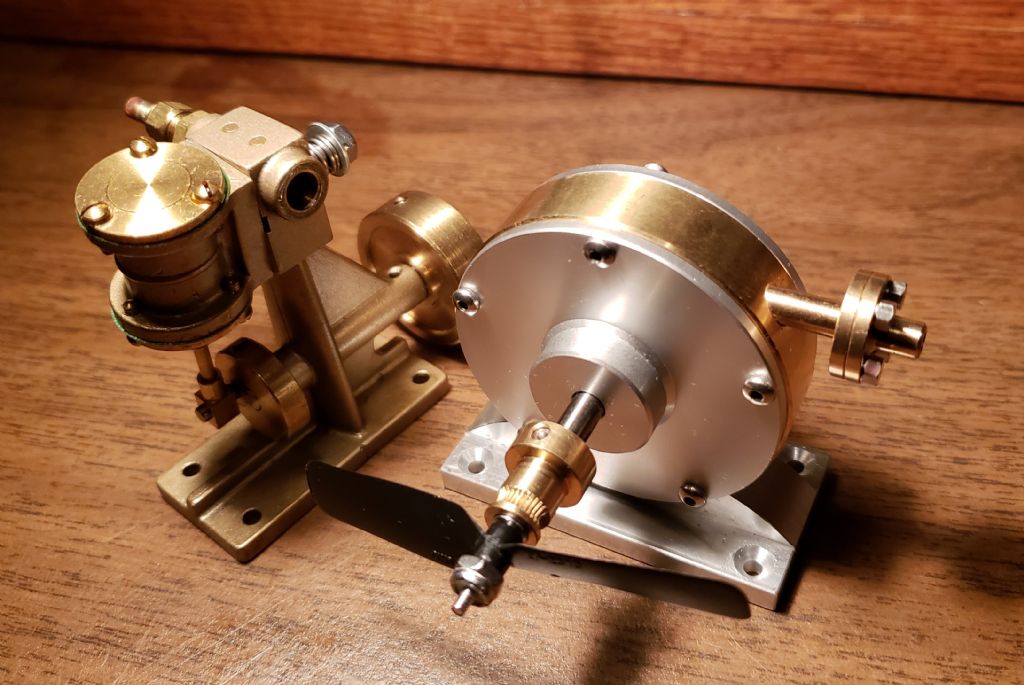
                                              It should be noted that although Radial Turbine 1 does not have a very high efficiency, the small steam engines typically used don’t do much better. The most common type of steam engines in small sizes use the oscillating cylinder. I found in my Testing Models thread that the Miniature Steam Models (MSM) Tyne shown in the following photo had a maximum efficiency of 6.0%. The Stuart Turner ST even with several modifications to improve the performance only got a maximum efficiency of 6.9%. These oscillating cylinder steam engines had their maximum efficiency at speeds of approximately 1,000 rpm and maximum powers of approximately 2 watts. That is a lower speed than needed for model boats. The maximum overall efficiency of Radial Turbine 1 with the 5.5 speed ratio gears was 5.7% with an output speed of approximately 2,900 rpm and a power of 1.7 watts. This output speed would probably be low enough for many of the model boat propellers. Michael Fueg used a overall speed ratio of 40:1 in his model train described in the posts starting with 11/01/2023 post shown on the previous page. These posts show how the same turbine as Radial Turbine 1 bought with a two-stage gear speed reducer was mounted in his train and links to videos that show the train running on steam. For Radial Turbine 1 with the 13.5:1 speed ratio gearbox that came with Michael’s turbine, the output power would be approximately 1.4 watts at a speed of 1,700 rpm using my largest airbrush compressor. The overall efficiency would be approximately 4.6% based on 2 stages of speed reduction and 80% efficiency for each stage. Michael’s reversing gearbox had an additional speed reduction plus idler gears that made the overall speed ratio 40:1 and would further reduce the efficiency to about 3.7% and the power to about 1.1 watts. This is based on running on air, the energy available with steam is much larger and if the steam is dry or superheated the efficiency would be about the same but the power would increase.

                                              rt1 & tyne.jpg

                                              #631884
                                              Turbine Guy
                                              Participant
                                                @turbineguy

                                                Since Werner Jeggli has tested on steam, I will try to confirm my last statement in the previous post that a good boiler could supply much more energy. In a test using the boiler of his PRR-S2 locomotive he obtained an average power of 11.3 watts with two 0.8mm (0.031) nozzles that had a combined throat area of 0.00151 in^2. The nozzle throat area of Radial Turbine 1 with the 0.037” nozzle is 0.00107 in^2, so his boiler could easily supply the steam for the larger nozzle used in the test with air. The steam temperature at the entry to the turbine was approximately 186C (367F) with a pressure of 3.5 bar (66 psia). The saturated temperature for 66 psia steam is 299F, so the steam was superheated 68F. The mass flow in his test was 25 g/min (3.3 lb/hr) and enthalpy drop was 115 btu/lb, so the energy available to his turbine was approximately 113 watts. This is over 3 times the amount of energy available with the tests using my airbrush compressor. The overall efficiency of his turbine in this test was 10.0%. My tests of Axial Turbine 2 that uses the same rotor reached an overall efficiency of 13.4% running on air. There are many differences between our turbines, so this only shows approximately what to expect.

                                                Edited By Turbine Guy on 03/02/2023 15:35:12

                                                #633075
                                                Turbine Guy
                                                Participant
                                                  @turbineguy

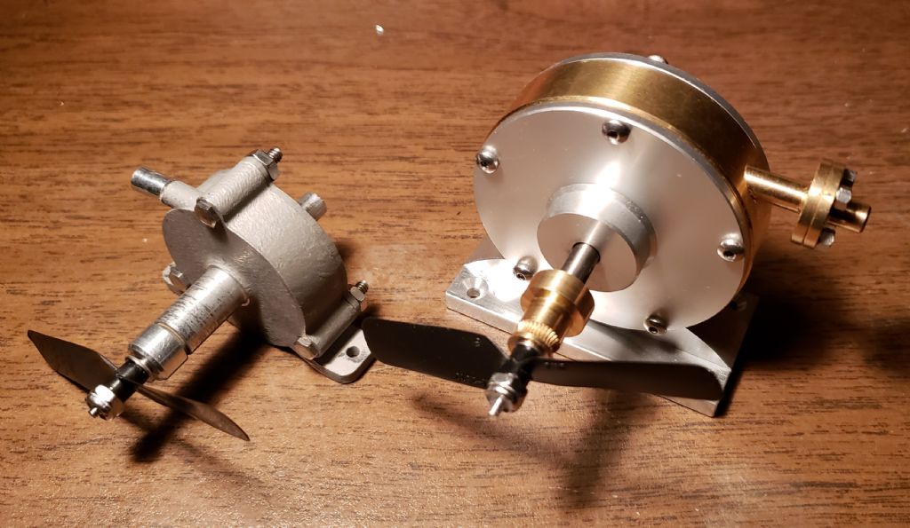
                                                  I ran a test of Radial Turbine 1 and Tangential Turbine 5B with my Stuart 504 boiler. The following photo shows the turbines, and the following test sheet shows the results. I used the GWS EP 2510 propeller for these tests because I thought that it would keep the turbines from over speeding with the energy available. It kept Radial Turbine 1 from over speeding but I had to periodically remove and slide back in one of the wick burners when I ran Tangential Turbine 5B. Since I had to remove some of the energy when Tangential Turbine 5B started to overspeed, the energy and speed were not constant so what is shown in the test sheet for this turbine is the approximate averages. I picked Tangential Turbine 5B for comparison with Radial Turbine 1 because it has the easiest to machine rotor and has almost matched the maximum efficiency of the best turbine I have tested. This was the first test using steam for the bearings that came in Radial Turbine 1 and the dental bearings used in Tangential Turbine 5B. They both seemed unaffected by the steam. Tangential Turbine 5B spun the GWS EP 2510 propeller to its maximum operating speed of 28,000 rpm with air at 20 psig immediately after the test with steam. Comparing the performance of these turbines running on air or steam, Radial Turbine 1 seemed to get the best benefit. It had a maximum power with air of 1.6 watts that increased to 3.1 watts with steam. The maximum power of Tangential Turbine 5B was about the same running on air or steam. Radial Turbine 1 is the first of the turbines I have tested to get a substantial increase in power with steam from the Stuart 504 boiler when compared to the performance with air from the Master TC-96T airbrush compressor. The Reynold Number and wet steam losses have offset the extra energy available for the other turbines. Apparently the wide spacing and small number of blades of Radial Turbine 1 are not affected by these losses nearly as much as the other turbines.

                                                  rt1 & tt5b.jpg

                                                  turbine test results 48.jpg

                                                  #633177
                                                  Turbine Guy
                                                  Participant
                                                    @turbineguy

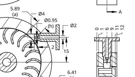
                                                    I saved for last, the discussion of what I think is one of Radial Turbine 1’s best features. This is the way they made the nozzle a separate piece. With this type of nozzle both ends are exposed, so the drilling, reaming, and forming requirements of each end can be met. The nozzle can be converging only like in this turbine or a truly supersonic nozzle with a diverging exit. Even used as a converging only nozzle, it has the big advantage of allowing space for the gas to expand before striking the rotor. My testing and Werner Jeggli’s testing have shown the need for this space if a converging only nozzle is used for gases expanding to supersonic velocities. The following copy of a portion of a page from ‘Steam Turbines by Edwin F. Church, third edition’ explains how the gas exits the nozzle. The enlarged portion of the drawing in the 24/01/2023 post added below shows the space provided with Radial Turbine 1’s nozzle. Another advantage of this nozzle is that the hole through the wall of the housing is relatively large compared with the nozzle bore. I have broken several small drills or had them wander when trying to go through a thick wall. Drills as small as 0.6mm used by these tiny turbines are extremely delicate. If I had seen this type of nozzle before I did my last turbines, I would have done something similar.

                                                    sonic nozzle shock waves 2.jpg

                                                    rt1 nozzle.jpg

                                                    #634975
                                                    Turbine Guy
                                                    Participant
                                                      @turbineguy

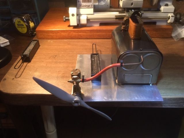
                                                      I wanted to make some tests of my model turbines with my Stuart Twin Drum boiler. This small simple boiler is what I hoped could be used with model turbines and be competitive with the small model steam engines. This boiler did not come with a throttle valve and was intended to be used with the Stuart ST oscillating cylinder steam engine like shown in the following photo. When I made the first nozzles for some of my model turbines they had a throat diameter of less than 0.028” so that they could be run with the Stuart Twin Drum boiler without a throttle valve. The best results of any of the model turbines I ran with the Stuart Twin Drum boiler were with Axial Turbine 2 that had a nozzle size of 0.024”. When I got my larger airbrush compressor and started testing with the Stuart 504 boiler, the optimum nozzles sizes became larger, so I had increased the nozzle sizes on all my turbines. I decided to add an orifice in the outlet tube of the Twin Drum boiler to act as a throttle and run Tangential Turbine 5B and see how the throttled performance compared with the best I have got without the throttle. The following test sheet shows this comparison. The output power turned out to be about the same even though the throttling lost over half of the energy available to Tangential Turbine 5B. This illustrated the increase in turbine efficiency running at sonic velocity compared with running at supersonic velocities. The axial turbines ran better on steam than my tangential turbines because a space between the nozzle and the rotor could be provided that would allow the steam exiting the nozzle to expand as needed to go supersonic. Moving the axial rotor away from the nozzle worked but was a compromise. Even with the compromises of the turbines shown in the first two tests of the following test sheet, they appeared to exceed the performance of the Stuart ST oscillating cylinder steam engine the Stuart Twin Drum boiler was intended to be used with. The test I made with a Stuart ST steam engine with everything the way it came and run with the Stuart Twin Drum boiler; it turned an APC 8×6 propeller at approximately 1,500 rpm. This propeller requires 0.4 watts to run at this speed according to the manufacture’s propeller performance sheets. The turbines would require a 12:1 speed reducer to run at the Stuart ST speed. This would probably require two stages and assuming the 80% efficiency per stage I found with the test of Radial Turbine 1, the power of the turbines would be reduced to 0.7 watts. This is still quite a bit better than the 0.4 watts of the Stuart ST steam engine.

                                                      The third test was running the steam without being throttled. Even with the large nozzle size, the flow out of the boiler was steady but at a very low pressure. Although the overall energy output of the boiler was less than half than with throttling or a small nozzle, the power and efficiency increased significantly. These tests indicate that a better way to achieve supersonic velocities is needed to run at the higher pressures.

                                                      The type of nozzle shown in the last post would provide this space without increasing the leakage caused by the gaps and should help any of the turbines that run on supersonic air or steam.

                                                      test setup.jpg

                                                      turbine test results 49.jpg

                                                      Edited By Turbine Guy on 25/02/2023 18:50:11

                                                    Viewing 25 posts - 426 through 450 (of 583 total)
                                                    • Please log in to reply to this topic. Registering is free and easy using the links on the menu at the top of this page.

                                                    Advert

                                                    Latest Replies

                                                    Home Forums Stationary engines Topics

                                                    Viewing 25 topics - 1 through 25 (of 25 total)
                                                    Viewing 25 topics - 1 through 25 (of 25 total)

                                                    View full reply list.

                                                    Advert

                                                    Newsletter Sign-up