Model Turbines

Advert

Model Turbines

Home Forums Stationary engines Model Turbines

Viewing 25 posts - 401 through 425 (of 583 total)
  • Author
    Posts
  • #608119
    Turbine Guy
    Participant
      @turbineguy

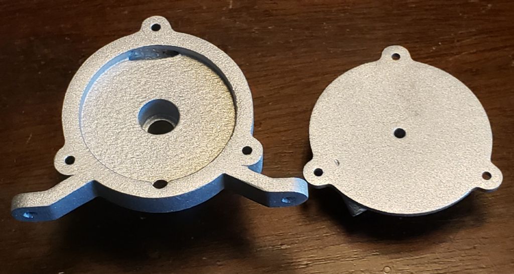
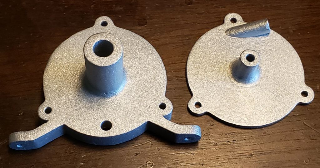
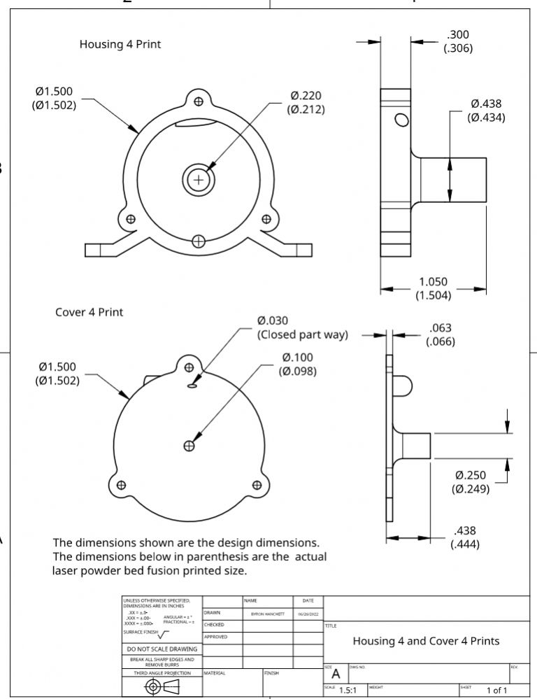
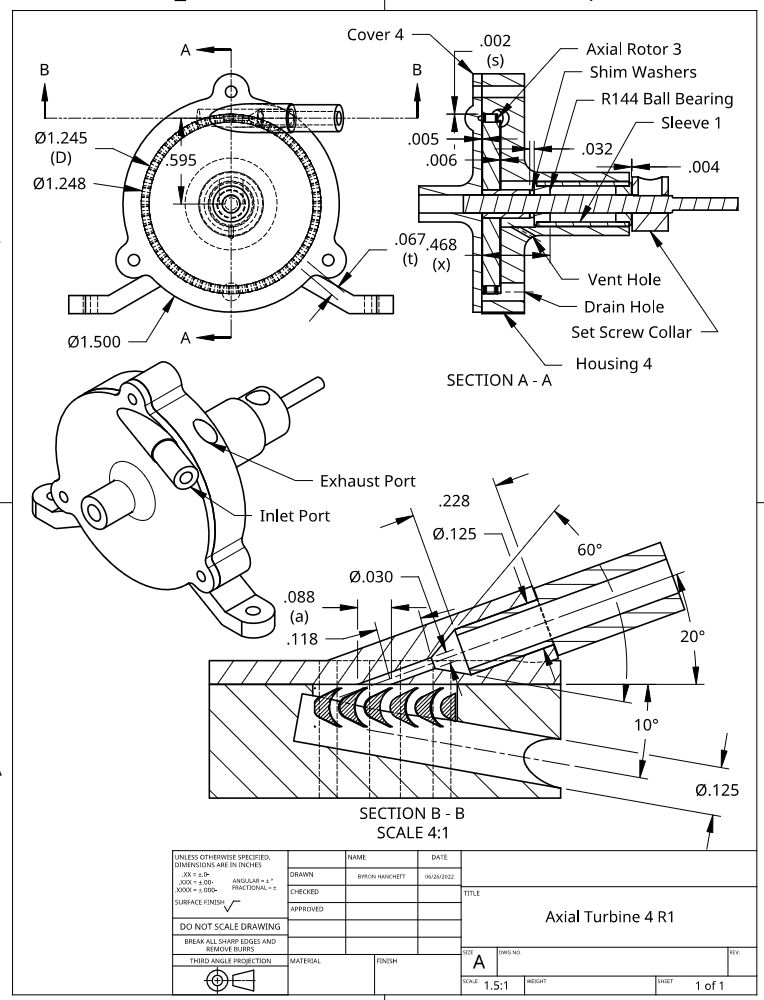
      I received the Housing 4 and Cover 4 prints from Shapeways shown in the following photos. I measured a few dimensions on each print and added the as printed dimension in parenthesis below the design dimension shown in the following drawing.

      axial turbine 4 prints photo 1.jpg

      axial turbine 4 prints photo 2.jpg

      housing 4 & cover 4 prints.jpg

      Advert
      #609688
      Turbine Guy
      Participant
        @turbineguy

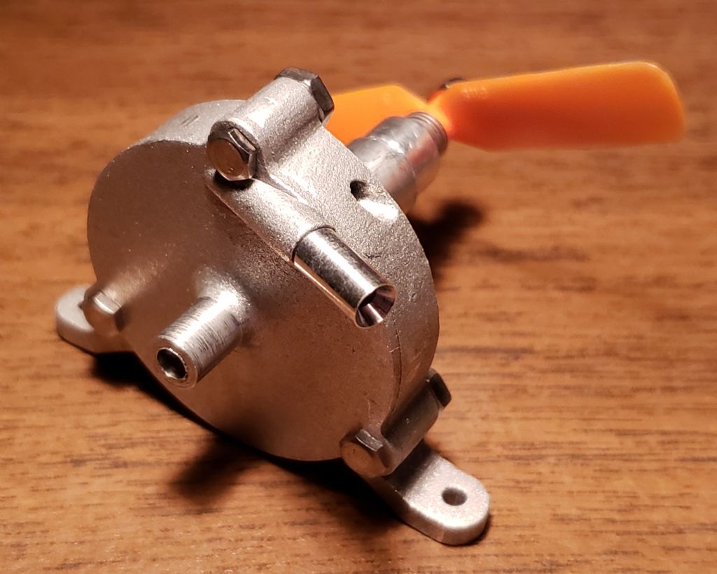
        I finished the machining of Cover 4 and assembled Axial Turbine 4 as shown in the following photo. I updated the album for Axial Turbine 4 adding more photos and the following drawing that shows the position of the parts in the assembly for the first test. I will start the testing and add the results in the next posts.

        axial turbine 4 photo 5.jpg

        axial turbine 4 r1.jpg

        #609952
        Turbine Guy
        Participant
          @turbineguy

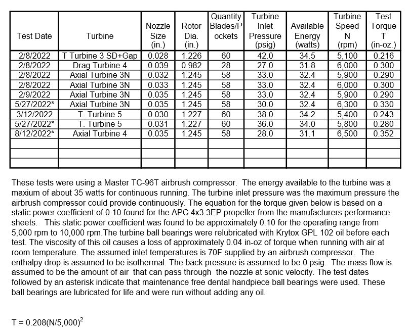
          I finished the first round of testing of Axial Turbine 4. I need to explain why I prefer to find the optimum position of the rotor using the APC 4×3.3 EP propeller even though it cannot get the power and efficiency of the GWS 2508 EP propeller. When I made my first turbine, I thought that a right-hand propeller would spin clockwise when looking at the front. I found out that it should spin clockwise when looking at the back like from the cockpit of a plane. I could not get a left-hand propeller in the small size, but I can put the propeller on backwards, so it is rotating in the correct direction. This pushes the air away from the turbine instead of pulling the air over the turbine. I should have designed my next turbines to run the correct direction. As I have mentioned in earlier posts the ball bearings need some axial clearance to run with the least resistance. I have found that at least 0.004” gives the best results. Running the propellers left-hand, pushes the rotor away from the inner ball bearing and toward the cover. The clearance must be on the outer ball bearing, so I use a 0.004” feeler gage between it and the set screw collar. The APC 4×3.3 EP propeller is a left-hand propeller, so it pulls the rotor toward the inner ball bearing and the rotor shims control its position. This is more precise than using the feeler gage. The right-hand propeller has another advantage when held on with a nut. If something strikes the propeller while running, the force is in a direction to tighten the nut. Running the propellers left-hand like I have been doing has the opposite effect. During these last tests, I struck the propeller while it was running and it loosened the nut enough to let the propeller slip. I heard the speed raise way above the 28,000 rpm limit I had been running. Fortunately, the rotational losses were large enough to keep the speed below the breaking point of the rotor. Sorry for using such a long winded explanation, but I think it is important to show the advantages of using a right-hand propeller and running it in the correct direction.

          I updated the table shown in the 13/03/2022 Post to include the best performance I got with Axial Turbine 4 using the APC 4/3.3 EP propeller as shown below. I will update the table shown in the last post and add it in the next post that will explain why I need to look at the performance at low and high speeds.

          turbine test results 38.jpg

          #611443
          Turbine Guy
          Participant
            @turbineguy

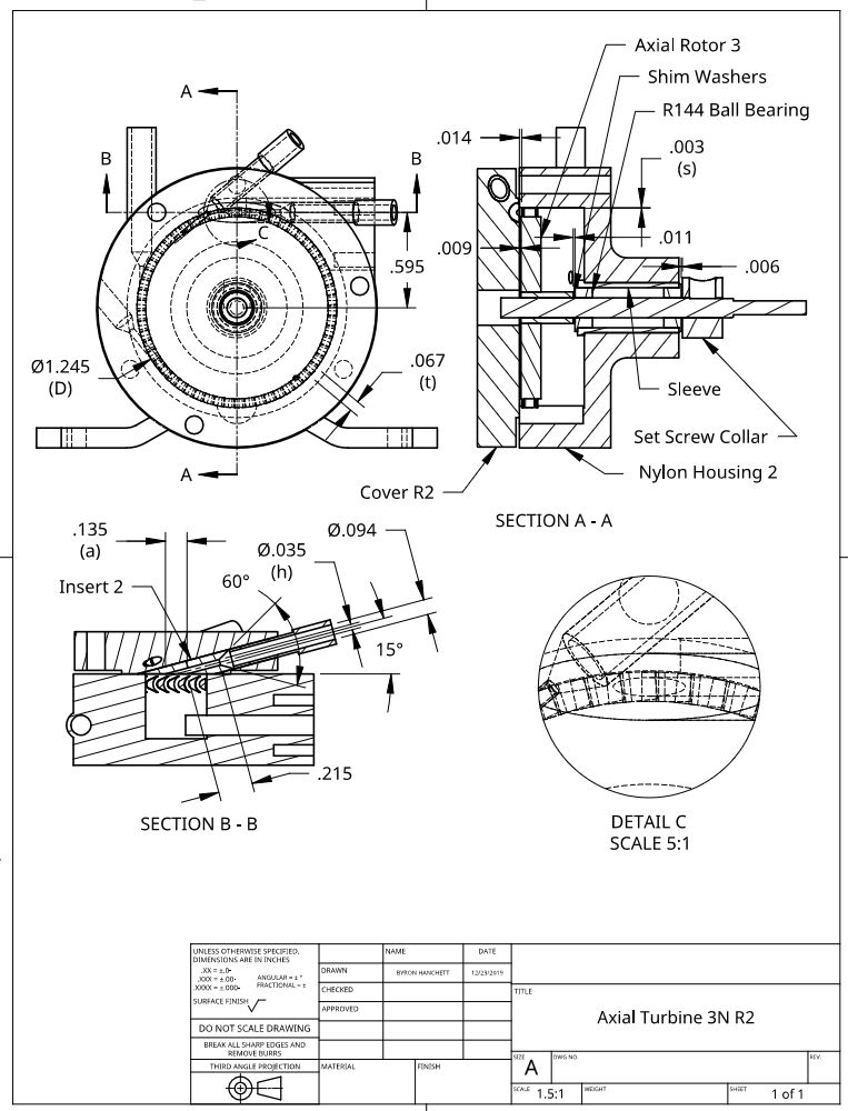
            I tried to get a good test of Axial Turbine 4 with the GWS 2508 Propeller, but my results were not repeatable. The ball bearings appear to need more clearance than the small gap on each side of the rotor allows. I need to change the direction of rotation of the propeller as discussed in the last post. This will require a new housing and cover. It will also require mounting the rotor on the shaft in the opposite direction. The results of the test with the APC 4×3.3 EP propeller shown in the last post indicate that Axial Turbine 4 is capable of slightly more torque than Axial Turbine 3N which is the next best. The major difference between these turbines is the covers and gaps between the rotor and the housing. Both had their best performance with very small distances between the rotor and cover. Axial Turbine 4 had a very small distance between the rotor and housing whereas Axial Turbine 3N had a relatively large distance between the rotor and the housing. You can see this by comparing the drawing in the 15/08/2022 post with the drawing for Axial Turbine 3N shown below. Cover 4 has an inlet angle of 20 degrees and Cover R2 has an inlet angle of 15 degrees. The larger inlet angle allows the large diameter section of the nozzle to get closer to the inside face of the cover. This reduces the length of the throat section from 0.215” for Cover R2 to 0.118” for Cover 4. This reduces the pressure drop due to friction but also decreases the overlap distance (a) from 0.135” to 0.088” respectively reducing the number of blades being filled. The larger inlet angle also decreases gas velocity in the direction the rotor is moving. To see which concept is more effective, I ran tests with Axial Turbine 3A and Axial Turbine 3A with Cover 4. The nozzle size was 0.035” for both covers. Everything was the same in these tests except the covers. The gap between the rotor face and cover was set at 0.004” and the pressure was held at 25 psig. With the APC 4×3.3 EP propeller, the maximum speed reached with Cover 4 was 5,500 rpm and 6,000 rpm with Cover R2. The 15 degree nozzle angle was clearly better. I am going to start designing Axial Turbine 5 that will have Axial Rotor 5 running the correct direction, a nozzle angle of 15 degrees, and allow for the gaps between the rotor, cover, and housing be adjustable.

            axial turbine 3n r2.jpg

            #612016
            Turbine Guy
            Participant
              @turbineguy

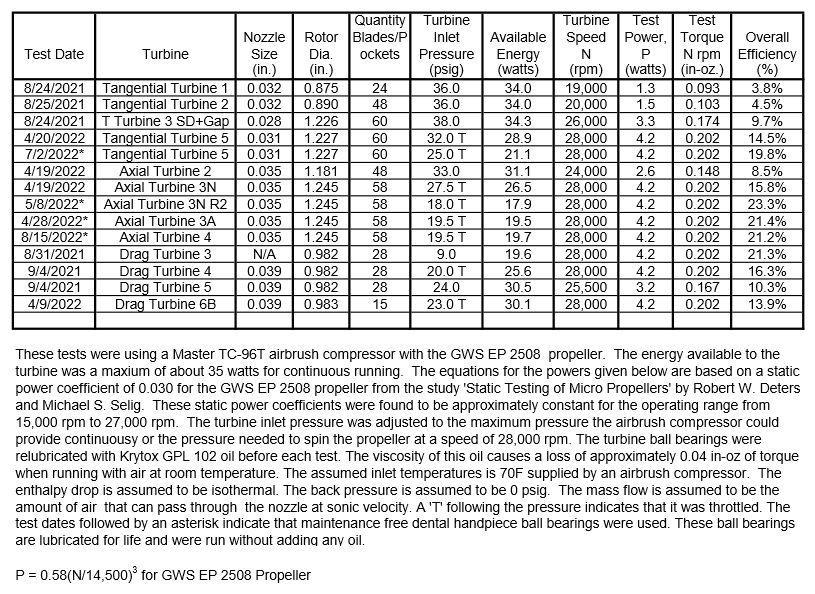
              I didn’t update the table shown in the 10/05/2022 Post when I first got the best performance of Axial Turbine 4 with the GWS 2508 EP propeller because I thought it should do better. I couldn’t understand why it was approximately the same efficiency as Axial Turbine 3A as shown in the following updated chart. I found that Cover R2 used on Axial Turbine 3A was quite a bit more efficient that Cover 4 used on Axial Turbine 4 as explained in the last post. I thought that this might explain why the open rotor of Axial Turbine 3A did as well as the same rotor with the tight clearances of Axial Turbine 4. I ran some more tests with the GWS 2508 EP propeller and found that the maximum performance was as I found in the 8/15/2022 test. Although it was difficult to get the rotor in the optimum position, the test results were consistent enough to indicate that this is the best performance of Axial Turbine 4 with the existing parts. I plan to design a new cover with a 15 degree nozzle angle and try that on the existing housing before changing the direction the rotor rotates.

              turbine test results 39.jpg

              #614299
              Turbine Guy
              Participant
                @turbineguy

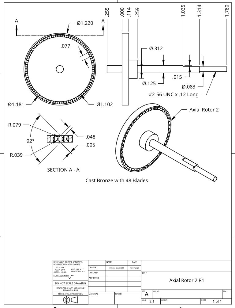
                I decided to change the rotor shaft size of Axial Rotor 2 to 1/8” so that it could be used with the dental ball bearings. This also gave me a chance to center the rotor on the shaft better. Werner Jeggli also gave me Axial Rotor 1 that I showed the balance marks on in the 29/10/2021 Post since it revealed how little material needed to be removed for balancing. As I explained in that post, I had to remove much more material from Axial Rotor 2 because the mounting hole I made was off center. When I changed the shaft size to 1/8” in revision 2 as shown in the following drawing, I got the new mounting hole much closer to the center of the rotor. This plus using the dental ball bearings will give a substantial boost in performance. I ran my first test with Axial Rotor 2 R1 and it raised the performance significantly, but when I tried finding the optimum position of the rotor in the housing, my laser tachometer failed. I’ve ordered another laser tachometer and will start my testing again when it arrives.

                axial rotor 2 r1.jpg

                #614604
                Turbine Guy
                Participant
                  @turbineguy

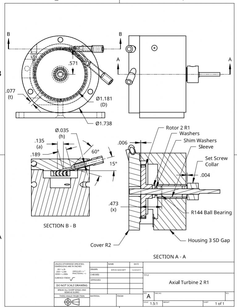
                  I received my new laser tachometer and resumed the testing of Axial Turbine 2. The following drawing shows the position of the rotor for the best performance. I will add the test results in the next post.

                  axial turbine 2 r1.jpg

                  #614622
                  Turbine Guy
                  Participant
                    @turbineguy

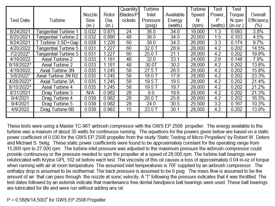
                    I added the best performance of Axial Turbine 2 to the test sheet shown in the 01/09/2022 Post and show it below. Getting the rotor better centered on the shaft and using the dental ball bearings did raise the efficiency substantially. I got the best performance with a nozzle size of 0.033” and then tried a 0.035” nozzle size as shown on the drawing in the last post. The 0.033” nozzle worked the best. These last tests had the same problem of getting consistent performance with the GWS 2508 EP propeller. This propeller pushes the rotor towards the cover and relies on the outer ball bearing to set the final position. The relatively long distance from the outer ball bearing to the rotor allows more change in position due to thermal expansion or contraction and using a feeler gage to check the gap is not the most accurate way. I plan to try a ball bearing close to the rotor on each side. This should reduce the bearing friction and make it easier to get the rotor in the right position regardless of which way the load moves the rotor.

                    turbine test results 40.jpg

                    #614751
                    Turbine Guy
                    Participant
                      @turbineguy

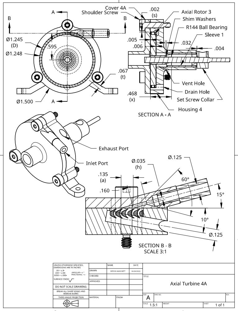
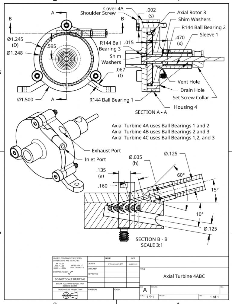
                      I designed a new cover for Axial Turbine 4 called Cover 4A. This cover is intended to verify that a nozzle angle of 15 degrees is better than the 20 degrees of the existing cover as discussed in the 27/08/2022 post. This cover will also allow me to add a ball bearing on the outside face of the rotor which should help hold the rotor in the correct position regardless of what propeller I use as discussed in the previous post. The following drawing shows this new cover in the first configuration I plan to try. This configuration will be called Axial Turbine 4A. The only difference between Axial Turbine 4A and Axial Turbine 4 will be the covers and will confirm if the 15 degrees nozzle angle is better.

                      Precision shoulder screws will be used to ensure the alignment is accurate enough for the ball bearing in the cover that will be used in the next configuration. The mounting holes will be reamed through both the cover and the housing for a very close fit with the shoulder bolts. These holes will be reamed while the cover is held in alignment with the housing by a dowel pin extending through the ball bearing bores of both. This is my plan, but I would appreciate any suggestions for a better way in ensure the alignment between the cover and the housing.
                      axisl turbine 4a.jpg

                      #614753
                      Michael Gilligan
                      Participant
                        @michaelgilligan61133

                        Posted by Turbine Guy on 24/09/2022 15:32:01:

                        […]

                        Precision shoulder screws will be used to ensure the alignment is accurate enough for the ball bearing in the cover that will be used in the next configuration. The mounting holes will be reamed through both the cover and the housing for a very close fit with the shoulder bolts. These holes will be reamed while the cover is held in alignment with the housing by a dowel pin extending through the ball bearing bores of both. This is my plan, but I would appreciate any suggestions for a better way in ensure the alignment between the cover and the housing.

                        […]

                        .

                        Sounds good to me

                        The only possible improvement I might suggest would be to use taper pins for alignment.

                        MichaelG.

                        #614798
                        Turbine Guy
                        Participant
                          @turbineguy

                          Thanks for the suggestion Mike. There is enough room to fit a couple of 1/16" taper pins in the housing wall if needed. Since I have the 1/8" reamers required for the shoulder bolts I will try that first.

                          #616437
                          Turbine Guy
                          Participant
                            @turbineguy

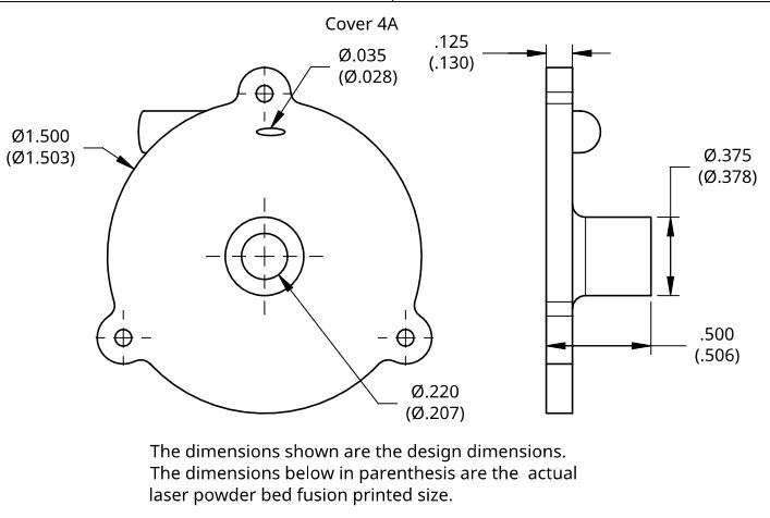
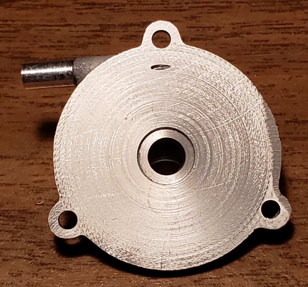
                            I received the print of Cover 4A from Shapeways and the following drawing shows the design and actual dimensions. This print was made with a selective laser melting process that uses a laser to scan and selectively melt metal powder particles, bonding them together and building a part layer by layer. The following photo shows the finished part.

                            printed cover 4a.jpg

                            cover 4a photo 3.jpg

                            #616446
                            Turbine Guy
                            Participant
                              @turbineguy

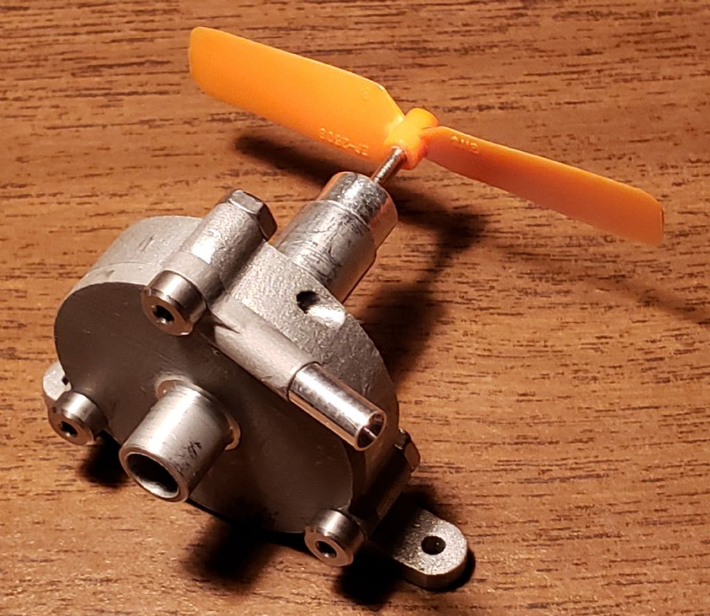
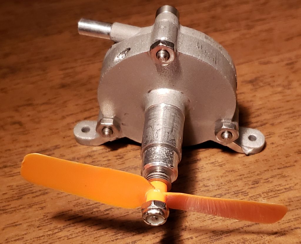
                              The reamed holes that I made for the precision shoulder screws mentioned in the 24/09/2022 Post, had a fit tight enough that each screw had to be bumped out to remove the cover. These screws lock the cover in the position that a very tight fitting dowel pin passed through the ball bearing bores of the cover and housing. The following picture shows Cover 4A mounted to Housing 4 using the precision shoulder screws.

                              axial turbine 4a photo 1.jpg

                              #616825
                              Turbine Guy
                              Participant
                                @turbineguy

                                Before I started the testing of Axial Turbine 4 again, I dropped one of the dental ball bearings that was used in the last tests shown in the 23/09/2022 post. The ball bearing rolled to some place I could not find. There are a few areas in my small shop that it could roll into and I would not be able to retrieve it. Anyway, the only other dental ball bearing I still had was one that was used in my drag turbines that might be damaged as explained in the 03/06/2022 Post. I ran Axial Turbine 4 with everything the same except for changing the one ball bearing to check the condition of that ball bearing. With a pressure of 20.0 psig it reached a speed of approximately 24,000 rpm compared to the 28,000 rpm obtained with almost the same pressure and the other ball bearings. This showed that the new combination of dental ball bearings was only 63% as efficient as the last combination. The results were repeatable and allowed the speed to get high enough to use this combination of dental ball bearings for comparing Axial Turbine 4 with Axial Turbine 4A. Pictures, drawings, and descriptions of the difference of Axial Turbine 4 and Axial Turbine 4A are shown in the posts starting on this page. With everything the same except for the covers, Axial Turbine 4A reached a speed of 28,000 rpm compared to the speed of 24,000 rpm reached by Axial Turbine 4. Cover 4A definitely improved the performance.

                                Cover 4A can hold a ball bearing and with the ball bearing placed there, will be called Axial Turbine 4B and discussed in the next posts.

                                #617187
                                Turbine Guy
                                Participant
                                  @turbineguy

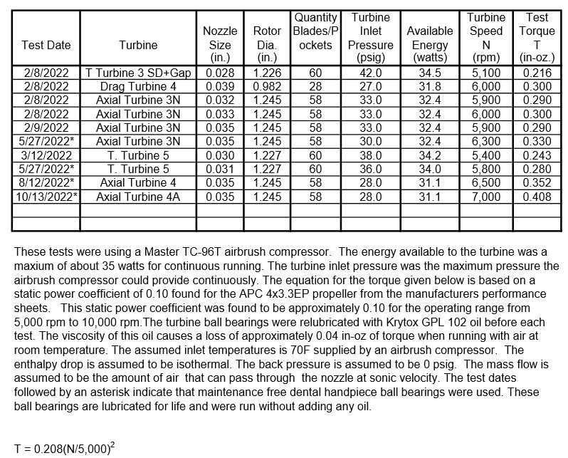
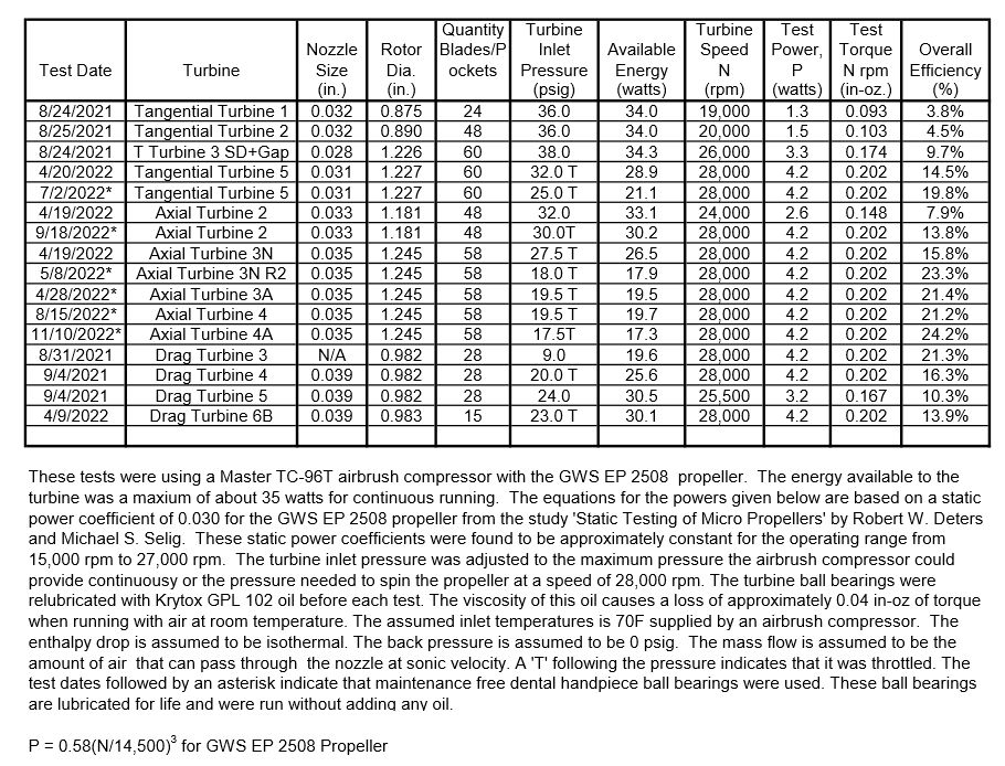
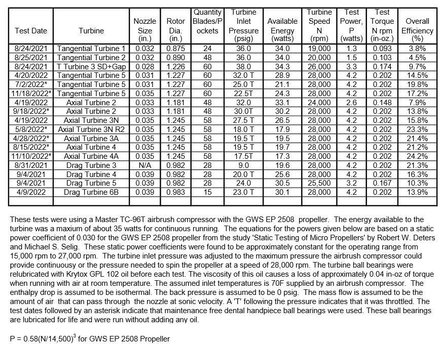
                                  I took the dental ball bearings that I thought were in good shape out of Tangential Turbine 5 and tried them in Axial Turbine 4. I used the APC 4×3.3 EP propeller since it gives the most consistent performance and ran the airbrush compressor at its maximum continuous pressure. The maximum pressure was 28 psig and the maximum speed reached was 6,600 rpm. This was almost the same result I got with the same 0.035” nozzle size as shown in the following table. This verified that these dental ball bearings were as good as those used when I tested Axial Turbine 4 on 8/12/2022. I then ran Axial Turbine 4A that had the rotor positioned the same so that the only difference was the covers. I updated the following table to show the results of that test. This last test also confirmed that Cover 4A worked better than Cover 4 but is a better comparison since it eliminated the effect of the clearance between the set screw collar and the outer ball bearing. These results were repeatable when I switched the covers back and forth. I tried the GWS EP 2508 propeller but could not repeat the performance found for Axial Turbine 4 in the 8/15/2022 test shown in the 01/09/2022 post. The performance with this propeller was about the same as described in the last post so the condition of the dental ball bearings is not the problem.

                                  turbine test results 41.jpg

                                  #617417
                                  Turbine Guy
                                  Participant
                                    @turbineguy

                                    Cover 4A gives the option of mounting a ball bearing in the cover so I tried three configurations. The following drawing shows the positions of the ball bearings and what I called each configuration. The testing of Axial Turbine 4A has been described in the last posts. I thought that adding a ball bearing in the cover would eliminate the problems running the GWS EP 2508 propeller on Axial Turbine 4. This propeller pushes the rotor toward the cover so the ball bearing in the cover can prevent contact. The problem I had with Axial Turbine 4B was the small distance between ball bearings 2 and 3 allowed the rotor to tip enough that it could contact the cover. This problem is caused by the small rotor side clearance of Housing 4. When I reduced the number of shim washers on ball bearing 2 to allow the rotor to move further into the housing and added shim washers to ball bearing 3 the contact could be avoided but the distance of the rotor from the cover becomes too large. I discussed how important the distance from the cover to Rotor 3 is in the 10/05/2022 Post. I found that for any of the housings or covers used with Rotor 3, the best performance is with the smallest gap between the rotor and cover. Axial Turbine 4C added ball bearing 1 to reduce the tilting of the rotor and resulted in getting the face of the rotor closer to the face of the cover. Even with the added friction of the extra ball bearing, Axial Turbine 4C ran better that Axial Turbine 4B but no better than Axial Turbine 4A.

                                    axisl turbine 4abc.jpg

                                    Edited By Turbine Guy on 15/10/2022 17:03:10

                                    #617864
                                    Turbine Guy
                                    Participant
                                      @turbineguy

                                      I was curious about the amount of force pushing the rotor toward the cover due to the thrust of the propellers. The maximum speed I was able to reach with Axial Turbine 4A turning the APC 4×3.3 EP propeller was 7,000 rpm as shown in the table of the 13/10/2022 post. The static thrust for this propeller from the manufacturers performance table at that speed is 1.12 oz. The static thrust for the GWS EP 2508 propeller is 0.92 oz at a speed of 27,000 rpm from the test results given in Static Testing of Micro Propellers by Robert W. Deters and Michael S Selig. The maximum thrust for these propellers at the maximum speed Axial Turbine 4A can turn them using the Master TC-96T airbrush compressor is around 1.0 oz. I thought that the force pushing the rotor away from the cover by the of gas exiting the nozzle should be larger than this. To see if this is true, I tried a simple test. I weighed the rotor and set screw collar using a precision scale and found the total weight to be 0.75 oz. I set the gap between the outer ball bearing and the set screw collar large enough that the rotor could contact the cover if pushed against it. I set the position of Axial Turbine 4A to where the propeller was above the housing. This allowed the weight of the rotor and set screw collar plus the thrust from the propeller to press the rotor against the cover. When I turned on the airbrush compressor with the turbine in this position, the propeller didn’t start to spin until a pressure of approximately 7 psig was reached. The turbine speed then climbed higher as the pressure rose until it reached the highest speed it had obtained at 20 psig with the position of the rotor shown in the last post. This indicated to me that a pressure as low as 7 psig could push the rotor away from the cover so only the shims on the inner ball bearing were important. This would allow me to find the best placement of the rotor with movements as small as my thinnest shim of 0.001”. I use the ‘x’ dimension shown in drawing since I get better readings with my digital caliper when the shims are compressed by the ball bearing. I next tried a ‘x’ value of 0.471” and found that this pushed the rotor to where there was light contact with the cover, so the maximum speed reached for 20 psig dropped quite a bit. This confirmed that an ‘x’ value of 0.470” was the maximum I could use without contact with the cover. I removed the 0.001” shim and tried running at 20 psig with an ‘x’ value of 0.470” again. This time the maximum speed reached was quite a bit less than before and the speed was erratic. I moved the set screw collar tight against the outer ball bearing eliminating all clearance and the speed increased almost up to the maximum obtained at 20 psig and was very stable. I changed the propeller to the larger APC 4×3.3 EP propeller and the maximum speed at 20 psig was the highest I have got at this pressure. The performance of this propeller has been very consistent regardless of the pressure or gap between the set screw collar and the outer bearing. I don’t understand what is causing this instability that only happens with the smaller propeller.

                                      #620563
                                      Turbine Guy
                                      Participant
                                        @turbineguy

                                        I finally found what was causing the instability when running my smallest propeller as discussed in the last post. After the last run I made with this propeller before finding the problem, the propeller was loose on the shaft. I was using a press fit to secure the propeller to the rotor shaft as suggested by the manufacturer of the propeller. Apparently, my repeated removing and pressing the propeller back on as required to change ball bearings or to reposition the rotor was weakening the fit. As the fit got looser, the centrifugal force on the propeller could weaken it enough to cause slippage. The press fit has worked fine on any of my turbines when the propeller was not pressed on or off too many times. I used another GWS EP 2508 propeller that had a slip fit between the propeller and the rotor shaft and secured it with a nut as shown in the following picture. With the rotor in the position shown in the 15/10/2022 post, Axial Turbine 4A achieved the best efficiency of any of my turbines as shown in the 11/10/2022 test in the following table. With the propeller secured with the nut, I could change back and forth between my larger and smaller propeller without any changes to the position of the rotor and the tests results were repeatable. The turbine ran smoothly in all positions, with either propeller, and at any pressure I tried. The results with the larger APC 4×3.3 EP propeller were almost identical to those shown for Axial Turbine 4A in the 13/10/2022 post.

                                        axial turbine 4a photo 2.jpg

                                        turbine test results 42.jpg

                                        #620580
                                        Michael Gilligan
                                        Participant
                                          @michaelgilligan61133

                                          Thanks for keeping this thread going … it’s very interesting to follow your progress.

                                          MichaelG.

                                          #620650
                                          Turbine Guy
                                          Participant
                                            @turbineguy
                                            Posted by Michael Gilligan on 11/11/2022 08:41:52:

                                            Thanks for keeping this thread going … it’s very interesting to follow your progress.

                                            MichaelG.

                                            Thanks Michael, its nice to know that at least a few people find this interesting.

                                            #621726
                                            Turbine Guy
                                            Participant
                                              @turbineguy

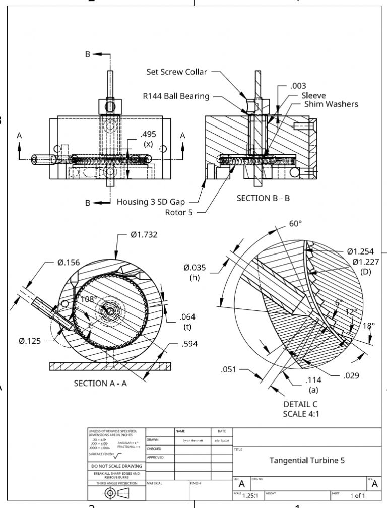
                                              I decided to enlarge the nozzle from 0.030” to 0.035” on Tangential Turbine 5 to match most of the other turbines shown below it on the test sheet of the10/11/2022 post. Comparing the performance of different turbines with the same nozzle size eliminates one variable. When I enlarged the bore of Housing 3D as described in the 24/05/2021 Post the next post explained why the power dropped running on air at low pressure. Tangential Turbine 5 uses the same housing, and the following drawing is revised to show the increased nozzle size and the placement of the rotor for best performance. The following test sheet added the 11/18/2022 test of this turbine with the larger nozzle size. In the next post I will explain why increasing the nozzle size reduced the efficiency.

                                              tangential turbine 5 r4.jpg

                                              turbine test results 43.jpg

                                              Edited By Turbine Guy on 18/11/2022 21:46:04

                                              #621816
                                              Turbine Guy
                                              Participant
                                                @turbineguy

                                                I mentioned in the last post that I would explain why I thought the efficiency of Tangential Turbine 5 dropped when I enlarged the nozzle size. One of the things I tried while looking for what was causing the instability running the smaller propeller on Axial Turbine 4A discussed in the 10/11/2022 post, was new ball bearings. When I ordered new bearings, I got a few extra ones and added them to Tangential Turbine 5. When I made the test run shown in the last post, it was with new dental ball bearings. In the 28/04/2022 Post I discussed the relatively large change in efficiency after the ball bearings bedded in. The efficiency of the 0.031” nozzle size was 15.7% with the new bearings that gradually increased to 17.1% after several runs. After even more runs, the efficiency increased to the 19.8% shown in the last post. Comparing the test results with new ball bearings with a few runs, the efficiency of the 0.035” nozzle is 17.2% and the efficiency with the 0.031” nozzle was 17.1%. This indicates the efficiency should be slightly better with the 0.035” nozzle and should exceed 19.8% when fully bedded in. This is another example of how important the condition of the ball bearings is to the efficiency of the tiny model turbines.

                                                #622069
                                                Turbine Guy
                                                Participant
                                                  @turbineguy

                                                  I am going to try improving the performance of Tangential Turbine 5 based on what I found on Axial Turbine 4. One of the reasons for the improvement in efficiency changing from Cover 4 to Cover 4A was the increase in the amount of rotor blades overlapped by the nozzle opening. This distance shown as 0.135” (a) in the following Axial Turbine 4A drawing is the overlap. This distance is 0.085” (a) with Cover 4 used in Axial Turbine 4. I believe that this substantial increase in overlap was the primary reason for the improvement in efficiency made by Cover 4A. The overlap (a) is shown on the assembly drawings of each of my turbines in my albums. Another improvement of Axial Turbine 4 was using tight clearances between the rotor faces and the cover and housing. Axial Turbine 3N R2 was the next best performer using Axial Rotor 3 as shown in the following test sheet. The main difference between Axial Turbine 3N R2 shown on the next post and Axial Turbine 4A is the clearance on the rotor faces. The tight clearance on both rotor faces did increase the efficiency. I started a design for a new printed aluminum housing and covers for Tangential Turbine 5 to try to optimize it that will be discussed in the next posts.

                                                  axisl turbine 4a.jpg

                                                  turbine test results 42.jpg

                                                  #622070
                                                  Turbine Guy
                                                  Participant
                                                    @turbineguy

                                                    axial turbine 3n r2.jpg

                                                    #622076
                                                    Roger Best
                                                    Participant
                                                      @rogerbest89007

                                                      We are getting big efficiency numbers now. Well done Turbine Guy.

                                                    Viewing 25 posts - 401 through 425 (of 583 total)
                                                    • Please log in to reply to this topic. Registering is free and easy using the links on the menu at the top of this page.

                                                    Advert

                                                    Latest Replies

                                                    Home Forums Stationary engines Topics

                                                    Viewing 25 topics - 1 through 25 (of 25 total)
                                                    Viewing 25 topics - 1 through 25 (of 25 total)

                                                    View full reply list.

                                                    Advert

                                                    Newsletter Sign-up