Model Turbines

Advert

Model Turbines

Home Forums Stationary engines Model Turbines

Viewing 25 posts - 351 through 375 (of 583 total)
  • Author
    Posts
  • #575411
    Turbine Guy
    Participant
      @turbineguy

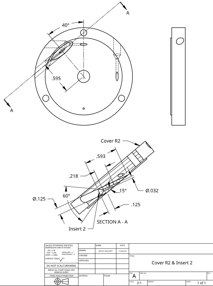
      I decided to add a nozzle for Axial Rotor 3 on the cover used for Axial Turbine 2. I broke a couple more drills trying to do the nozzles the same way I have done before and decided I would try something different. I bored a 1/8" (3.2mm) hole all the way through the Cover R2 as shown in the following drawing. This hole did not drift and broke through the cover in the right place. The plan was to make an insert as shown in the following drawing and use Loctite 290 to hold it in the hole. If the drill breaks in the insert, only the insert will be ruined and not the hole in the cover. I tried drilling the nozzle hole through before cutting the bevel on the first insert I made. The drill broke at about 3/4 the way through. Every one of the drills that were damaged, broke after going quite a ways into the hole. I think that the torque on the drill due to long contact is what is breaking the drills. I machined the bevel first on the next insert, so the drill only had to go through about half the distance. I ran the HSS drill at the top speed of the lathe and it passed all the way through. I installed Insert 2 and the second inlet tube in Cover R2 and used Loctite 290 to hold them in place. I added photos in my Axial Turbine 3 album showing the finished insert and the insert installed in Cover R2. After the Loctite cured over night, I tested the new nozzle for leakage and found the maximum pressure my air brush compressor could maintain with the 0.031" (0.79mm) nozzle size. The maximum pressure was 36 psi (2.4 bar) that matched the pressure I found when using my test nozzle, so the nozzle is working well.

      cover r2 & insert 2.jpg

      Advert
      #582932
      Turbine Guy
      Participant
        @turbineguy

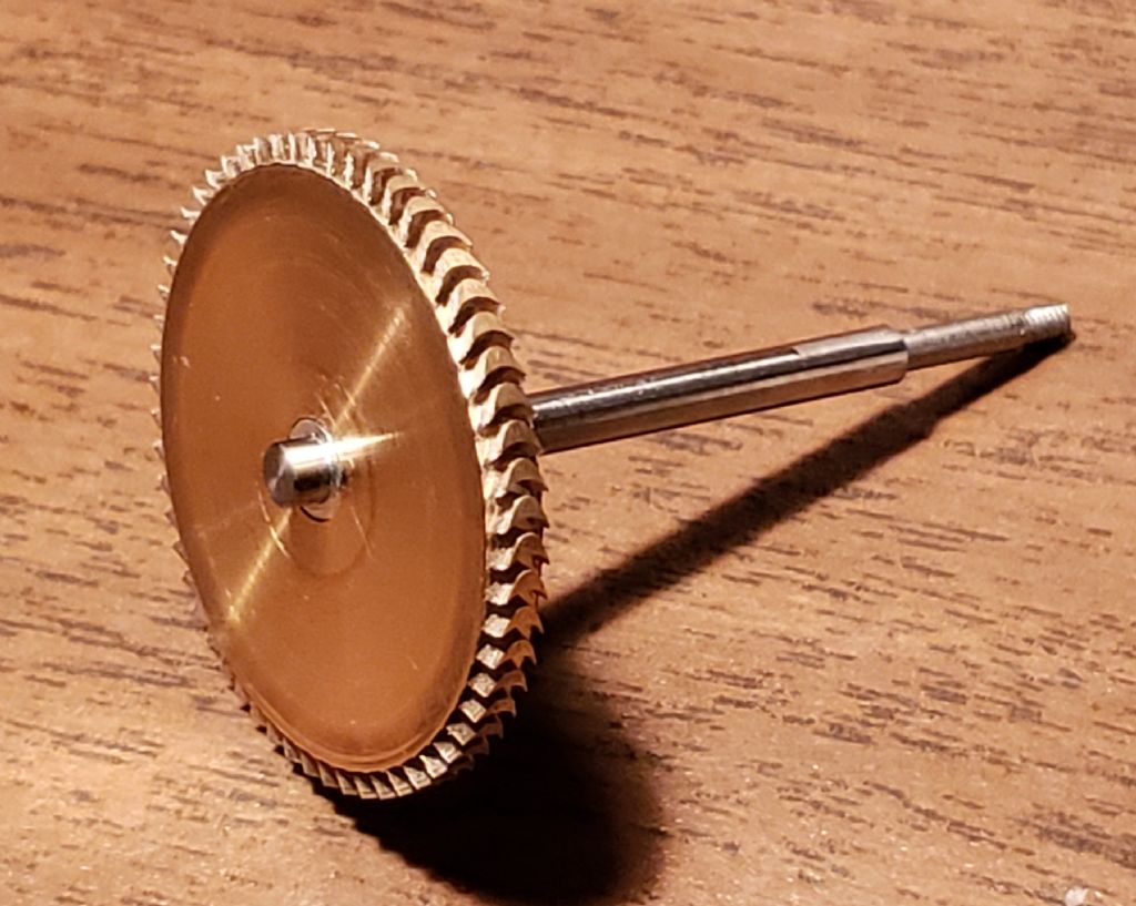
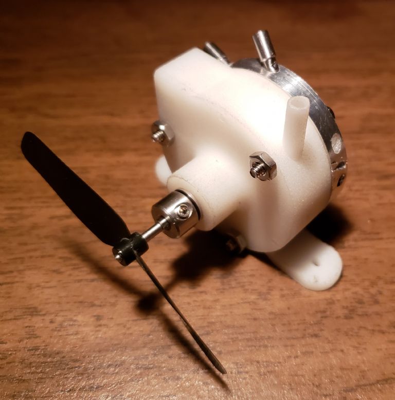
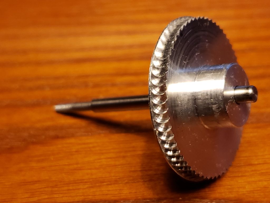
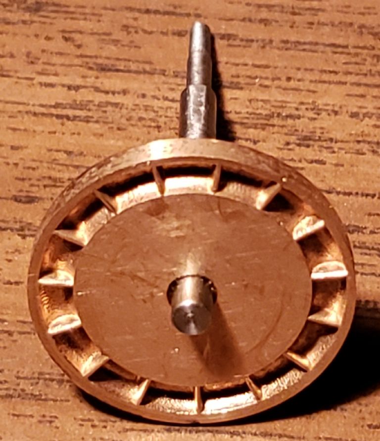
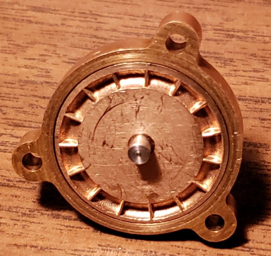
        I received the rotor Mike Tilby made for me shown in the picture below. As you can see from the photo his machining is outstanding, well beyond what I am capable of. He spent weeks making this rotor and I can’t thank him enough. I mounted his rotor on the shaft and sleeve I machined and will call this assembly Axial Rotor 3 R3. The R3 indicates the drawing for this assembly was revised three times. The original drawing showed the dimensions of the solid model of this rotor based on my understanding of what Mike intended to make. The later revisions were made for adjustments we had to make for machining or to fit in my existing nylon housing. I had already created a folder called Axial Turbine 3 for this rotor and it was intended to use my existing aluminum housing. I created a new folder called Axial Turbine 3N for using this rotor in my existing nylon housing. The second photo below is a photo of Axial Turbine 3N. I am updating the folder Axial Turbine 3N to show the parts, photos, and drawings. I will do the same for Axial Turbine 3 when I decide to use the aluminum housing.

        axial rotor 3 photo 2.jpg

        axial turbine 3n photo 1.jpg

        #582942
        Turbine Guy
        Participant
          @turbineguy

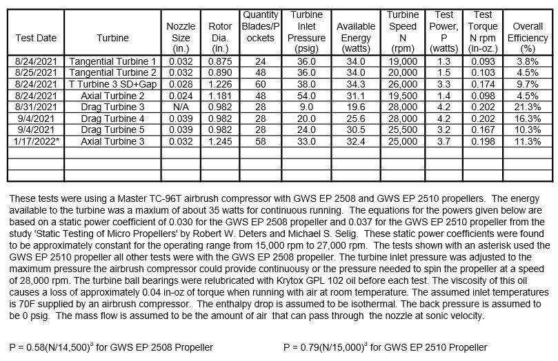
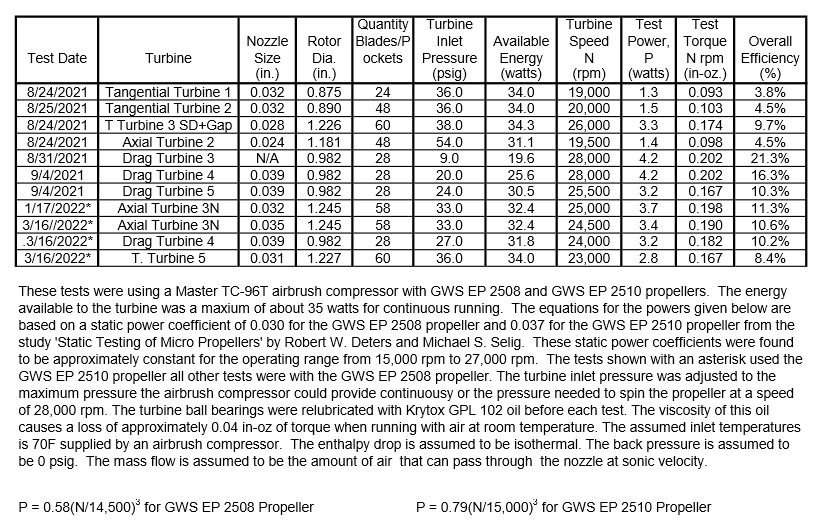
          I ran the first tests of Axial Turbine 3N and the results are shown in the following table. In the first test the speed went over 28,000 rpm with the GWS EP 2508 propeller I had been using, so I changed to the GWS EP 2510 propeller I recently purchased. The table shows the power required by each propeller and the source of the propeller test data. I was very happy to find the GWS EP 2510 propeller since it doesn’t require too much additional torque and the speed gets high enough to be a reasonable comparison of the test results with the other propeller. This is an update of the last test results I posted. I added the torque found from the tests since I feel this is what should be compared when tests are made with different loads. The results shown for Axial Turbine 3N are for the best distance of the face of the rotor from the face of the nozzle plate. I tried adding shims to move the rotor toward the cover plate until I found the position that gave the best performance. All my other turbines did not run over 28,000 rpm with freshly oiled bearings, the GWS EP 2508 propeller, and the maximum continuous output from my airbrush compressor except Drag Turbine 4. In the test of Drag Turbine 4 the pressure had to be lowered to the value shown to keep the speed below 28,000 rpm. I plan to run a test with Drag Turbine 4 to see what it can do with the full output of the airbrush compressor. The drawing Axial Turbine 3N R1 shown in album Axial Turbine 3N shows the position of the rotor in the housing for this test. This drawing was revised to show the actual dimensions of the rotor and nozzle size used in this test.

          turbine test results 24.jpg

          Edited By Turbine Guy on 29/01/2022 18:18:10

          #584293
          Turbine Guy
          Participant
            @turbineguy

            I noticed that after just a few tests of Axial Turbine 3N I could not reach the same maximum speed when comparing tests with everything the same. When I did tests to optimize my other turbines, I did not have this problem unless something damaged the ball bearings. I think that it is very important when testing a change, that the results of tests be close enough to confirm the results. The tests I started with Axial Turbine 3N were to find the optimum distance of the rotor from the face of the nozzle for a given nozzle size, propeller, and a given energy source. I add or remove shims and see if the maximum speed increases or degreases from the previous test. After finding the optimum spacing, I go back to the number of shims I used on the first test and see if the top speed is approximately the same as the first test. If the results of the first and last tests that had everything the same turn out to be very close, I feel the results are valid. I was able to do this many times with the tests of my other turbines that were checking something that I could change back to what was used in the original test. Not being able to do this with tests I started with Axial Turbine 3N caused me to try to find out what was different. The only thing that changed was the ball bearings. I could not get the ball bearings I had been using, so I tried the closest available ones. When I received the last ball bearings the quality did not appear to be as good as the previous ball bearings. I am going to try using a new pair of these last ball bearings and do my testing with a larger propeller and see if keeping the speed much lower results in the performance being more consistent. I just made my first run with everything the same as the test of Axial Turbine 3N shown in the last post except for using the APC 4×3.3 EP propeller. The maximum speed was 5,400 rpm and the resulting torque was 0.243 in-oz.. I will do several more tests with fresh oil before each test and everything else the same. If the maximum speed stays approximately the same, I will assume that the new ball bearings are working at the lower speed and repeat the tests for finding the optimum spacing.

            #584308
            Roger Best
            Participant
              @rogerbest89007

              Shucks, its always a pain when you change something and now its not right.

              Mikes wheel is amazing.

              This development is looking amazing. Thanks again for posting.

              #584456
              Turbine Guy
              Participant
                @turbineguy
                Posted by Roger Best on 06/02/2022 20:43:57:

                Shucks, its always a pain when you change something and now its not right.

                Mikes wheel is amazing.

                This development is looking amazing. Thanks again for posting.

                Hi Roger,

                Thanks for your kind remarks. I was glad to see someone comment about the outstanding rotor Mike Tilby made. I am disappointed that there has not been more remarks.

                The problem with the new ball bearings appears to have been caused by trying to run them at too high of a speed. I made several runs with the larger propeller and the results have been very consistent. The only thing I loose by testing at lower speeds is the amount of power produced. Since I only need to see if a change increased or decreased the performance, it doesn't matter what speed I do the testing at. I am going to start my testing again and do the tests with the larger propeller.

                Thanks for your comments,

                Byron

                #584678
                Turbine Guy
                Participant
                  @turbineguy

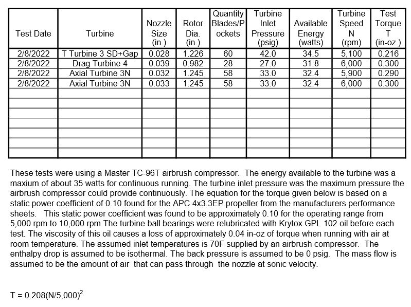
                  I found the optimum gap between the rotor and cover plate for Axial Turbine 3N to be 0.031” when running on my Master TC-96T airbrush compressor, using the APC 4×3.3 EP propeller, and with a 0.032” nozzle. The maximum speed obtained was 5,900 rpm and the corresponding torque was 0.290 in-oz. I next increased the nozzle size to 0.033” and ran a test without changing anything else. The maximum speed increased to 6,000 rpm with a corresponding torque of 0.300 in-oz. I ran tests of my Tangential Turbine 3 SD Gap and Drag Turbine 4 for comparison and made the following test sheet. I found that I get a significant loss in performance when the tests are run at temperatures much lower than 70 F. My shop is uninsulated and takes approximately a half hour to heat up on these cold winter days. This is not a problem if I need to run several tests like I did to make this test sheet. The next test I want to make is enlarging the nozzle size of Axial Turbine 3N. This test will only take a few minutes to perform but will require me to heat my shop up to approximately 70 F and make another test with the existing nozzle to verify that the results are consistent. If I get approximately the same performance with my existing nozzle, I will increase the nozzle size in small increments until I get a loss in performance. The nozzle size I end up with will be slightly less efficient than the previously tested nozzle, so I want to be very careful that my tests are valid.

                  turbine test results 25.jpg

                  #584873
                  Turbine Guy
                  Participant
                    @turbineguy

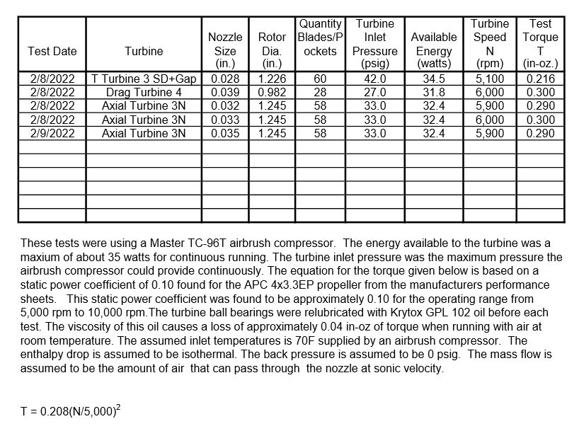
                    I ran Axial Turbine 3N with everything the same as the last test shown on the sheet of the previous post. It took approximately three hours to heat my shop to 70 F. My shop was at 47 F when I decided to start testing and I made a run at that temperature. The maximum speed obtained at 47 F was 5,600 rpm. I made another run at 60 F and the maximum speed obtained was 5,900 rpm. I then made a test at 70 F and the maximum speed obtained was 6,000 rpm. Since the test with the 0.033” nozzle had the same performance with everything the same as in the last post, I opened up the nozzle to 0.035”. The maximum speed reached was 5,900 rpm. I did multiple tests at 70F with the 0.035” nozzle and with fresh oil added before each test. The maximum speed reached was 5,900 rpm in each test, so the results were repeatable. Since the maximum speed dropped with the larger nozzle, I will assume the 0.033” nozzle size is the optimum for running with my Master TC-96T airbrush compressor. I updated the following test sheet to show the results of the last test. I did confirm that it is important to have the temperature close to the assumed 70 F when running a test. I also found that these latest ball bearing would only run for a short time without adding oil before the turbine would start losing speed. The ball bearings I had been using would make multiple runs before the speed would start dropping. I also found that the exhaust port had to be at the bottom even when running on air. With an inlet temperature of 70 F, the air after it expands in the nozzle is cold enough to condense the moisture in the air if the humidity is very high.

                    turbine test results 26.jpg

                    #584898
                    Turbine Guy
                    Participant
                      @turbineguy

                      Mike Tilby pointed out that I had not added the right nozzle size for the last test shown in the table of the previous post. I corrected this in the table shown below. turbine test results 27.jpg

                      #589702
                      Turbine Guy
                      Participant
                        @turbineguy

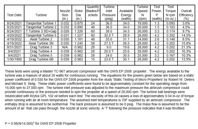
                        Rotor 3 SD evolved from rotors sized for my smallest boiler and single cylinder airbrush compressor I used for most of my testing, I decided to make a new rotor similar to Rotor 3 SD but more suitable for my twin cylinder airbrush compressor and largest boiler. I call this Rotor 5 and the assembly that it will be used in as Tangential Turbine 5. I made a new album for this turbine that shows photos, drawings, and test data. The photo shown below is Rotor 5 and the test sheet shown below is an update of the test sheet shown in the last post. You can see from the test sheet that this rotor performed better than Rotor 3 SD when used with my larger airbrush compressor. rotor 5 photo 1.jpgturbine test results 28.jpg

                        Edited By Turbine Guy on 13/03/2022 18:21:31

                        #590977
                        Turbine Guy
                        Participant
                          @turbineguy

                          I updated the following test sheet to show my best tangential turbine, axial turbine, and drag turbine running with the same two ball bearings, run at the same temperature, and with the tests made one right after another. This makes the conditions for these tests as close as I can make them. I delayed publishing these results because I thought I could get slightly higher performance with some higher quality unshielded bearings. I thought that without shields and having tighter tolerances these bearings would perform better. They didn’t with the oil that was in them as received or when re-oiled with Krytox GPL 102 oil. They performed no better or worse than the ball bearings I have been using. It really doesn’t matter what bearings or oil is used when comparting the performance of these turbines providing the same is used on all three.

                          turbine test results 29.jpg

                          #592272
                          Turbine Guy
                          Participant
                            @turbineguy

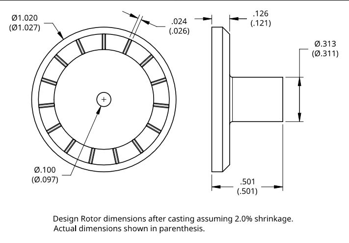
                            I decided to try a drag rotor with 90 degree blades that will be called Drag Rotor 6. The following photo shows the front view of the casting. The drawing shows the design dimensions of the casting with the actual measured dimensions in parenthesis.

                            drag rotor 6 cast photo 1.jpg

                            drag rotor 6 cast.jpg

                            #592374
                            Turbine Guy
                            Participant
                              @turbineguy

                              I completed the machining on Drag Rotor 6. The following photo shows the finished rotor and the drawing shows the final dimensions.

                              drag rotor 6 photo 2.jpg

                              drag rotor 6 r1.jpg

                              #592851
                              Turbine Guy
                              Participant
                                @turbineguy

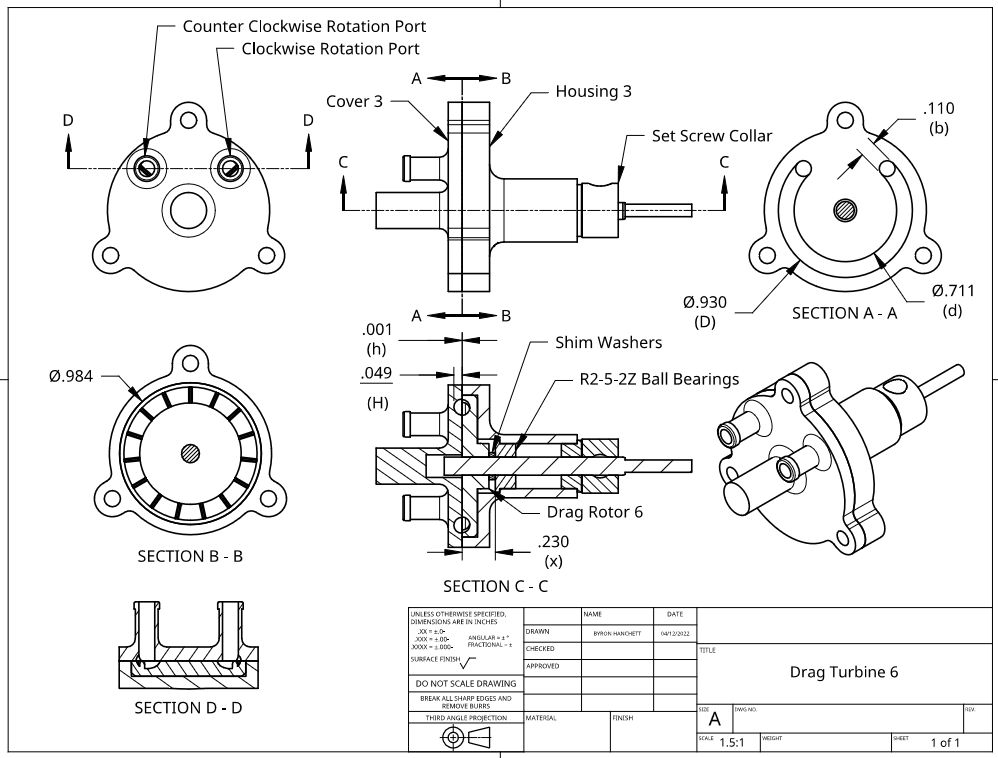
                                I ran Drag Rotor 6 with Cover 3 using the TC-96T airbrush compressor similar to the test described in the 17/08/2021 Post of Drag Turbine 3. The following is copied from that post with the values I measured in this test shown in parenthesis next to the values shown for that test.

                                “I made the following four pressure measurements. First, I measured the pressure with the cover plate removed and pressed tight against a flat surface. The pressure was approximately 6.5 psig (6.5 psig). That is the pressure required to push all the flow through the existing channel size with smooth walls on all sides. The second measurement was with the cover plate bolted tight to the turbine housing with the rotor supported by the ball bearing but pushed tight against the cover plate. The pressure was approximately 12.5 psig (10.0 psig). That is the pressure required to push all the flow through the existing channel size with blades and without leakage. The 6 psig (3.5 psig) increase in pressure was due to the resistance to flow that the blades cause. The third measurement was with the 0.007” (0.040) total thickness of shim washers keeping the face of the rotor as close to the face of the cover plate as I was able to do without any contact. The pressure was approximately 12.0 to 12.5 psig dependent on the rotor position(8.5 psig in all positions) . That is the pressure required to push all the flow through the existing channel size with blades and with leakage. The fourth pressure measurement was with everything the same as the third measurement except with the turbine running at a speed of 26,000 rpm (23,000 rpm). I was able to reach that speed with the GWS EP 2.5×0.8 propeller. The pressure was approximately 9.5 psig (7.0 psig).”

                                The power required by the GWS EP 2.5×0.8 propeller at 23,000 rpm is 2.3 watts and at 26,000 rpm is 3.4 watts. The power using Drag Rotor 6 was only 68% of the power using Drag Rotor 3 but the power of Drag Rotor 6 was the same running in either direction.

                                drag rotor 6 photo 1.jpg

                                Edited By Turbine Guy on 04/04/2022 13:32:25

                                #592855
                                Jon Lawes
                                Participant
                                  @jonlawes51698

                                  I really enjoy these posts, please keep them up.

                                  Thanks,

                                  Jon

                                  #592874
                                  Turbine Guy
                                  Participant
                                    @turbineguy

                                    Thanks for you kind remarks Jon. I’m glad you find these posts interesting. Each of the things I try is to give someone thinking about making a model turbine an understanding of what is involved in making the part(s) and what to expect in performance. I am hoping that having actual test results is helpful.

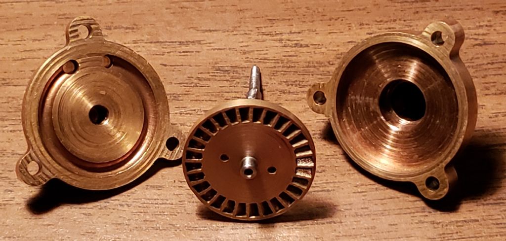
                                    Werner Jeggli in the 06/01/2021 Post suggested that a bidirectional turbine would be very helpful. These tests with only the rotor being different were intended to show how much loss in performance would occur using the 90 degree bidirectional blades of Drag Rotor 6 instead of the more efficient 40 degree blades of Drag Rotor 2. The following photo shows the housing, cover, and rotor of Drag Turbine 3, only the rotor was different in the comparison.

                                    drag turbine 3 parts.jpg

                                    #593219
                                    Turbine Guy
                                    Participant
                                      @turbineguy

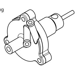
                                      I ordered a casting for the cover I intended to use with Drag Rotor 6 but this casting was rejected because the inlet and outlet tubes were too long. The following isometric drawing shows that cover in what was intended to be Drag Turbine 6. I changed the design adding bosses that will have tubes inserted to project to the needed length. The following photo shows the front view of Cover 6A Cast. The drawing shows the design dimensions of the Cover 6A Cast with the actual measured dimensions in parenthesis.

                                      drag turbine 6 r0.jpg

                                      cover 6a cast.jpgcover 6a cast photo 1.jpg

                                      Edited By Turbine Guy on 06/04/2022 15:47:49

                                      #593882
                                      Turbine Guy
                                      Participant
                                        @turbineguy

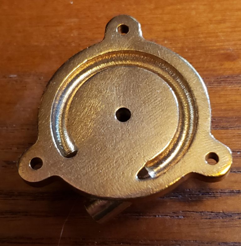
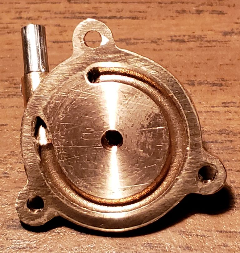
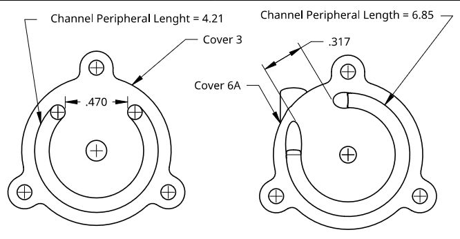
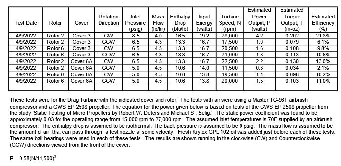
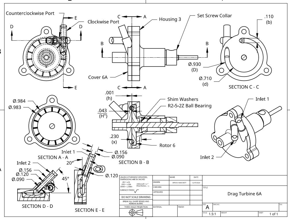
                                        I finished the machining of Cover 6A shown in the following photos. This cover was intended to improve the performance by reducing the change in direction of the flow into and out of the flow channel. To determine the reduction in pressure loss I pressed Cover 6A tightly against a flat plate and measured the pressure required to force the maximum flow through in each direction. The required pressure was 5.0 psig in both directions. The pressure required to pass the maximum flow for Cover 3 was 6.5 psig in both directions. Cover 6A reduced the pressure required for maximum flow by approximately 1.5 psi. I thought this reduction in pressure would result in higher performance for Cover 6A compared with Cover 3, but despite which drag rotor I used, the performance was always better with Cover 3. I checked Cover 6A for flatness after lapping it on an oilstone. I could not detect any spots with clearance between a ground bar and the rotor face anywhere. I finally found that the increase in leakage of Cover 6A more than offset the improvement of reducing the pressure drop. The following drawing shows the increase of channel peripheral lengths and reduction in minimum distance between ports for Cover 6A compared to Cover 3 that significantly increases the leakage.

                                        cover 6a photo 1.jpg

                                        cover 6a photo 2.jpg

                                        drag covers 2.jpg

                                        #593961
                                        Turbine Guy
                                        Participant
                                          @turbineguy

                                          The following test report shows the results of my testing of various combinations of rotors and covers intended to show the advantages or disadvantages of each combination. I initially planned on finding the best combination that gave approximately the same performance running in either direction. Mike Tilby suggested that I also look at how Drag Rotor 3, that was designed to run in only one direction, performed running in the opposite direction. He pointed out that even though the efficiency in one direction might be much higher, the performance in the opposite direction might be adequate. The tests show how Cover 3 outperformed Cover 6A in all combinations as I discussed in the last post. The tests also showed that even though Drag Rotor 3 was designed to run in only one direction, it could still produce a significant amount of power in the opposite direction.

                                          turbine test results 30.jpg

                                          #594151
                                          Turbine Guy
                                          Participant
                                            @turbineguy

                                            Because Drag Rotor 6 can be used with any of my existing covers, I decided to give each combination a name. The combination of Cover 3 and Drag Rotor 6 is Drag Turbine 6. The combination of Cover 6A and Drag Rotor 6 is Drag Turbine 6A. The combination of Cover 5 and Drag Rotor 6 is Drag Turbine 6B. The drawings for Drag Turbine 6 and Drag Turbine 6A are shown below. I hope this will make it a little clearer what was compared in the last post. I added Drag Turbine 6B since Cover 5 has given me the best performance of any of the covers with any rotor running in one direction. The nozzle in the inlet restricts the flow too much for the rotation to be reversed. Drag Turbine 6B will be covered in the next posts.

                                            drag turbine 6.jpg

                                            drag turbine 6a.jpg

                                            #594301
                                            Turbine Guy
                                            Participant
                                              @turbineguy

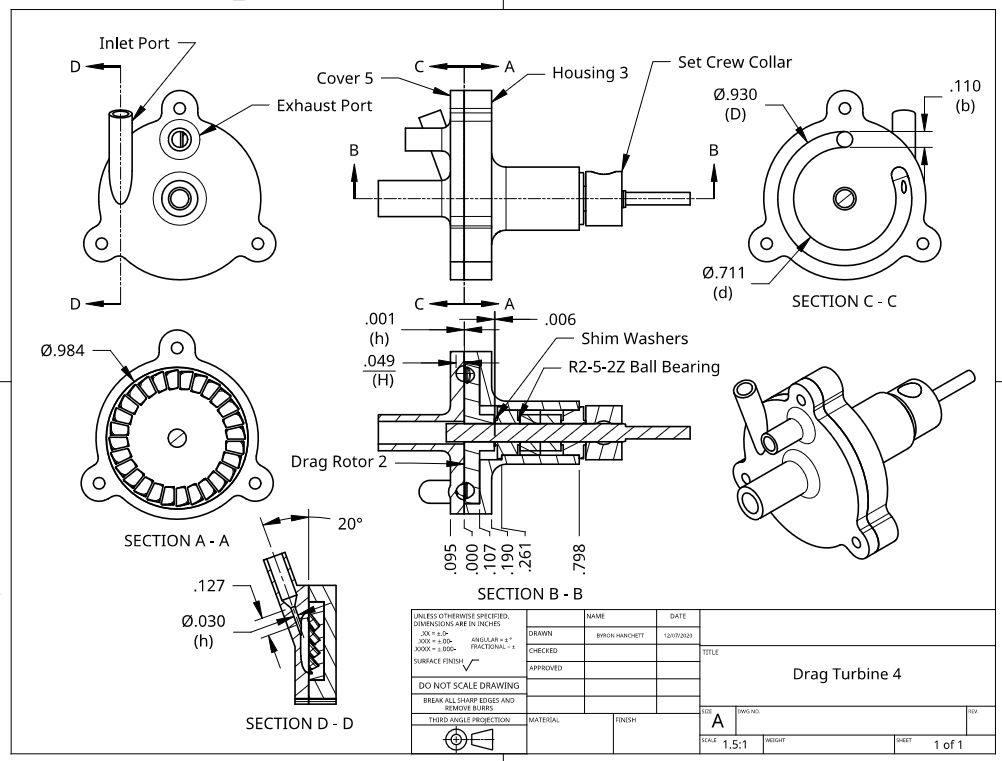
                                              Adding a nozzle on the inlet ports makes Cover 5 different from any drag turbines I have seen. I made Cover 5 for Drag Rotor 5 to help reduce the leakage and it was very effective on Drag Turbine 5. The nozzle is small enough to cause the air or steam to go supersonic so the impact on the blades is significant. I found in my testing, that the drag turbines using Cover 5 had something unique in the way they produced torque to match the requirements of different propellers. All my impulse turbines whether axial or tangential made less torque as the speed increased. Drag Turbine 4 and Drag Turbine 6B shown in the following drawings actually started to get an increase in torque when the speed got high enough that the corkscrew type of circulation in the channel became more significant as will be shown and explained with the test results added in the next post.

                                              drag turbine 4.jpg

                                              drag turbine 6b.jpg

                                              #594315
                                              Turbine Guy
                                              Participant
                                                @turbineguy

                                                The following test report is for Drag Turbine 4 and Drag Turbine 6B shown on the drawings of the last post. Both turbines showed a drop in torque when the propeller was changed from an APC 4×3.3 EP propeller to the GWS EP 2510 propeller but showed an increase in torque when the propeller was changed from the GWS EP 2510 to the GWS EP 2508. Drag Turbine 4 was throttled to keep the speed at 28,000 rpm when using the GWS EP 2508 propeller so that is why the torque was the same as Drag Turbine 6B but its efficiency was higher. As the speeds got higher Drag Turbine 6B started to get closer to the performance of Drag Turbine 4 but always had less efficiency. If these drag turbines were given a load that allowed them to run at higher speeds they may be capable of out performing the impulse turbines since their torque appears to be capable or increasing with speed. All my turbines would perform better at higher speeds so I am going to try to find better ball bearings that will last longer running at the higher speeds. I am also going to try to see if I can find an adjustable load that can be run at high speeds like Werner Jeggli’s test setup he showed in the 18/06/2019 Post and I commented on in the 10/09/2020 Post.

                                                turbine test results 31.jpg

                                                #594397
                                                Turbine Guy
                                                Participant
                                                  @turbineguy

                                                  I decided my best source for highspeed bearings would be the ceramic ball bearings made for dental handpieces. These bearings are used in the tiny turbines that run on air at speeds over 200,000 rpm. Because of the large numbers of dental handpieces in use, these ball bearings are readily available at relatively low cost. I found in the Dental Bearing Sizes link a description of features and sizes of the ball bearings used by the different manufacturers of dental handpieces. The most common size was 1/4” OD x 1/8” ID. Only one of the manufacturers used an OD of 5/16”, the size used in all my turbine housings. I wanted to try a maintenance free ceramic ball bearing so I selected the ball bearings used in the Star 430 handpieces and ordered the ball bearing shown below. This will require me to press fit sleeves in the bearing bores of my turbine housings but will give me the most options for purchasing dental bearings.

                                                  dental bearing.jpg

                                                  Edited By Turbine Guy on 14/04/2022 15:34:16

                                                  #595294
                                                  Turbine Guy
                                                  Participant
                                                    @turbineguy

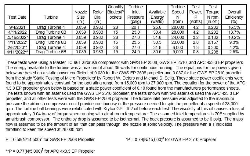
                                                    I believe the fairest way to compare the different turbines is to run them with the same propeller, with the same energy source, and at as close to the same speed as possible. Since most of the turbines I have tested used the GWS EP 2508 propeller, I decided to make a test sheet using only this propeller. Since the latest turbines can overpower this propeller, I throttled the air to keep the propeller to a maximum speed of 28,000 rpm. The throttling reduces the energy available to the turbine, so the efficiency of the turbine is the best comparison of the performance. The lower the energy required to turn the propeller at its maximum speed results in the highest efficiency.

                                                    I decided to remove the sleeve in the nozzle of Axial Turbine 2 and run a test with a nozzle size closer to the other turbines. I successfully removed the sleeve in the nozzle bore so I could change the diameter from 0.024” to 0.035”. The 0.035” diameter gave me the best performance and is better suited to my largest airbrush compressor.

                                                    I ran Tangential Turbine 5, Axial Turbine 3N, and Drag Turbine 4 with the same ball bearings so that I can see the change in performance with the dental bearings when I try them. I already had run Drag Turbine 4 with the GWS EP 2508 propeller, but I ran it again to see if the ball bearings used in these last tests gave the same performance as in the previous test. The results were identical.

                                                    I received the dental ball bearings described in the last post and the items needed to make the reduction sleeve for the existing turbine housings. I will add the reduction sleeve to one of the turbine housings and run a test of the dental ball bearings.

                                                    The date shown for the test of Drag Turbine 6B should have been 4/9/2022.
                                                    turbine test results 32.jpg

                                                    Edited By Turbine Guy on 21/04/2022 15:21:44

                                                    #595561
                                                    Turbine Guy
                                                    Participant
                                                      @turbineguy

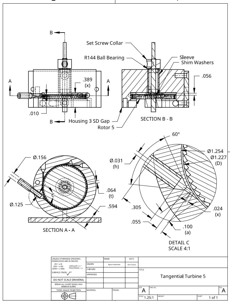
                                                      I added a sleeve to Housing 3 SD Gap to reduce the bore used by the ball bearings from 5/16” diameter to 1/4” diameter. The following drawing shows the sleeve added and the bearings changed to the R144 size used by the dental handpieces. I installed the Ameriden 11FS dental bearings shown in the 14/04/2022 post and ran the first tests that will be described in the next post.

                                                      tangential turbine 5 r3.jpg

                                                    Viewing 25 posts - 351 through 375 (of 583 total)
                                                    • Please log in to reply to this topic. Registering is free and easy using the links on the menu at the top of this page.

                                                    Advert

                                                    Latest Replies

                                                    Home Forums Stationary engines Topics

                                                    Viewing 25 topics - 1 through 25 (of 25 total)
                                                    Viewing 25 topics - 1 through 25 (of 25 total)

                                                    View full reply list.

                                                    Advert

                                                    Newsletter Sign-up