Model Turbines
Model Turbines
Home › Forums › Stationary engines › Model Turbines
- This topic has 605 replies, 28 voices, and was last updated 9 June 2025 at 15:11 by
Turbine Guy.
-
AuthorPosts
-
29 July 2021 at 15:14 #556291
Turbine Guy
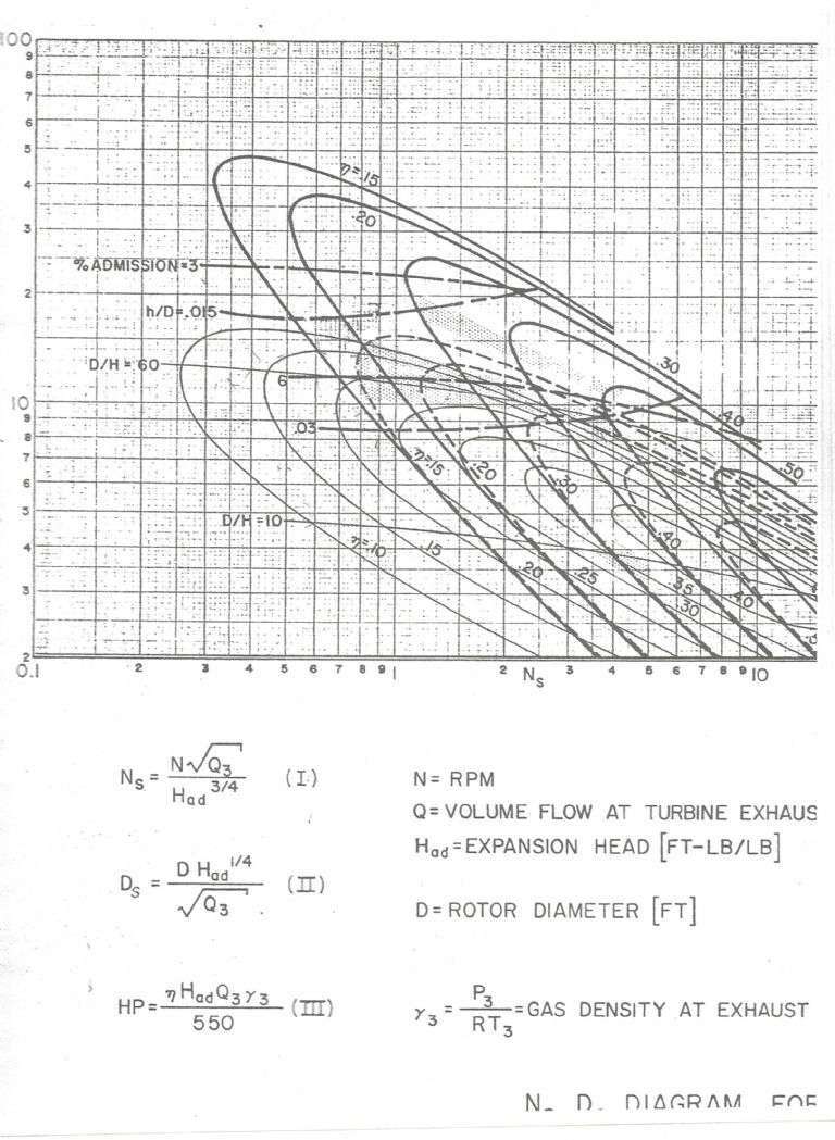
Participant@turbineguyPosted by Turbine Guy on 09/12/2020 18:23:48:The chart shown below and in some earlier posts is copied from ‘A Study Of High Energy Level, Low Output Turbines’ prepared by Dr. O. E. Balje for the Department of the Navy in December 1957. This chart illustrates the maximum performance he estimated for various types of turbines when optimized. The heavy solid lines in the chart are for axial turbines. The dashed lines are for Terry turbines. The thin solid lines are for Drag turbines. The units for the volume flow are ft3/sec and lb/ft3 for the gas density. Dr. Balje intended this chart be used by determining the volume flow at the turbine exhaust (Q3) and expansion head (Had) of the supply gas.
The quote from this post shows the equations and units for finding the specific speed Ns and specific diameter Ds for the Ns Ds Diagrams like the one for axial impulse turbines with small number of blades I will show in the next post.
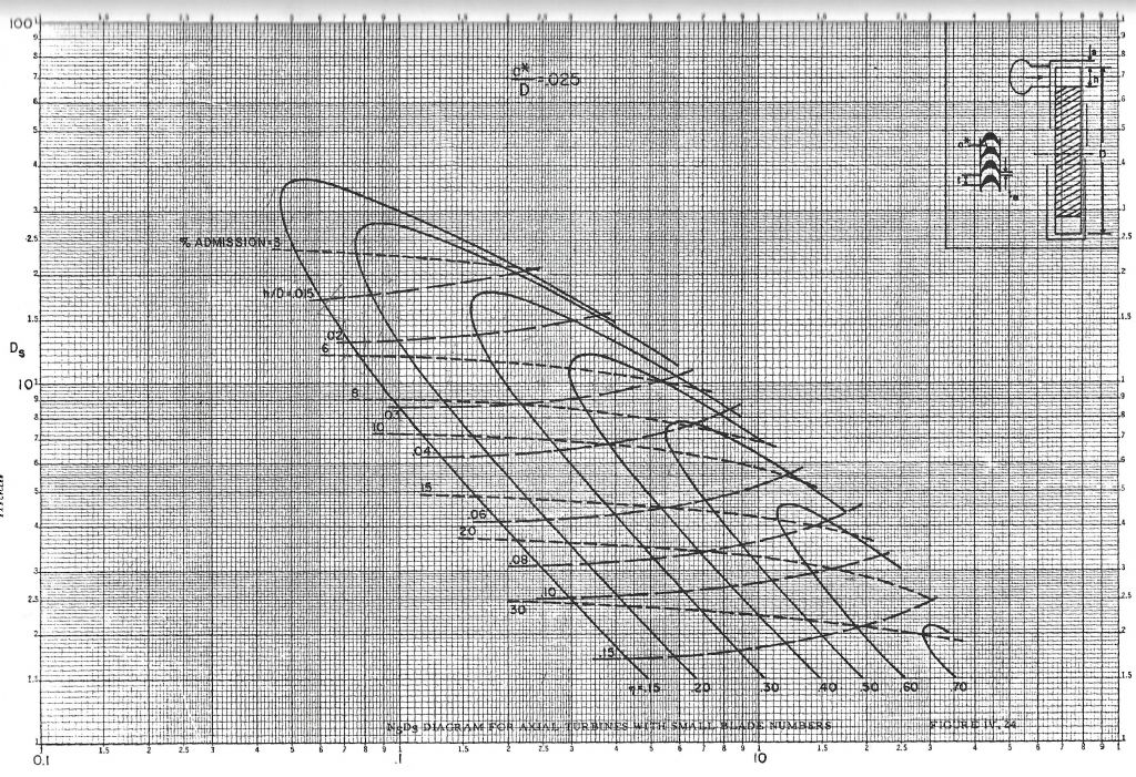
29 July 2021 at 16:28 #556301Turbine Guy
Participant@turbineguyThe following Ns Ds Diagram is the one mentioned in the last post. Using the mass flows, enthalpy drops, and turbine speeds given in the 26/07/2021 post and a rotor outside diameter of 1.181”, the values of Ns and Ds can be calculated for my test and Werner’s test. For my test, Ns is 0.50 and Ds is 14.5, and the corresponding maximum efficiency from the following Ns Ds Diagram is approximately 10%. For Werner’s test, Ns is 0.68 and Ds is 14.5, and the corresponding maximum efficiency from the following Ns Ds Diagram is approximately 15%. To obtain these efficiencies, the steam would have to be dry and the Reynolds number greater than 200,000. As shown in the posts of 27/07/2021 and 28/07/2021 the steam was wet and the Reynolds number was lower than 200,000 for both these tests. These posts showed how to correct the efficiency to account for this. The correction for moisture was 0.65 and the correction for Reynolds number was 0.44 for my tests. The correction for moisture was 0.90 and the correction for Reynolds number was 0.62 for Werner’s tests. With these corrections the estimated maximum efficiency for my test is 3% and 8% for Werner’s test. The actual efficiencies were 3% for my test and 9% for Werner’s test so Dr. Balje’s corrections are very conservative since the rotor and nozzles weren’t optimum. The point I am trying to make, is how wet steam and Reynolds number below 200,000 can drastically reduce the efficiencies of tiny turbines.
30 July 2021 at 15:20 #556414Turbine Guy
Participant@turbineguyI decided to see what the Ns Ds diagram of the last post with corrections would estimate for the test of Axial Turbine 2 running on air shown in the 19/07/2021 Post. For this test the turbine speed was 23,000 rpm, the rotor diameter was 1.181”, the mass flow was 2.0 lb/hr, the enthalpy drop was 34 btu/lb, and the exhaust specific volume was 13.3 ft^3/lb. For these values, Ns is 0.94 and Ds is 14.6. From the Ns Ds diagram shown in the last post, the maximum efficiency is approximately 20%. The rotor tip speed was 119 ft/sec and the kinematic viscosity was 0.000181 ft^2/sec resulting in a Reynolds number of 81,000. The correction for this Reynolds number is 0.64. Multiplying this correction to the maximum efficiency of 20% yields an efficiency of 13%. The energy available to the turbine for this test was approximately 20 watts and the actual power was 2.3 watts, so the actual efficiency was 11.5%. This confirmed that the low Reynolds number reduces the efficiency substantially and appears that Dr. Balje’s correction is conservative for air as well as steam. This also confirmed how useful his methods and diagrams are for estimating the efficiency if you know all the parameters needed. It also shows why my turbines did better running on air than with wet steam.
14 August 2021 at 20:13 #558256Turbine Guy
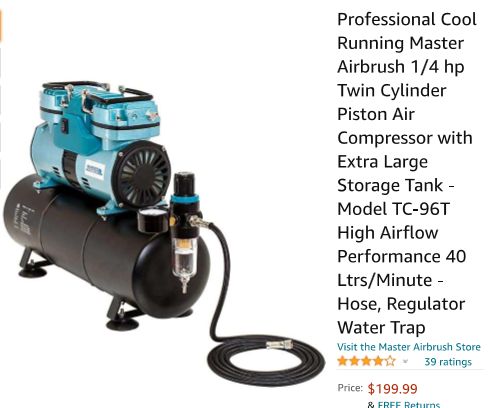
Participant@turbineguyI tried running my Stuart 504 boiler with two burners to confirm the power I got from Drag Turbine 5 in the test shown in the 09/07/2021 Post. The relief valve opened at around 30 psig so I couldn’t get the pressure up to the 35 psig pressure that resulted in the GWS EP 2508 propeller spinning at 30,500 rpm for a power of 5.4 watts. The relief valve keeps releasing at a lower pressure each time I try another test. The spring must need replacing since the relief valve doesn’t leak until it reaches a certain pressure. This pressure should remain about the same but doesn’t anymore. I prefer to do my testing with an airbrush compressor since it is so consistent and doesn’t require near as much time to setup and run a test. I need higher mass flow with my Drag Turbine 5 since the test I was trying to confirm gave a large jump in power when the mass flow increased. I decided to get a twin cylinder airbrush compressor that has about twice the mass flow of my existing single cylinder airbrush compressor. This will allow me to run tests using air with higher mass flows and the pressure can be maintained more consistently. The airbrush compressor I just ordered (shown below) is a Master TC-96T that is a twin cylinder version of my existing airbrush compressor that I have been very pleased with. This airbrush compressor is scheduled to arrive next Monday so I should be able to check the effect of having more mass flow available with all my turbines.
 17 August 2021 at 18:24 #558677
Turbine Guy
Participant@turbineguyI ran Drag Turbine 3 with the TC-96T airbrush compressor similar to the test described in the 12/03/2021 Post using the TC-20 airbrush compressor. The following is copied from that post with the values I measured in this test shown in parenthesis next to the values shown for that test.
“I made the following four pressure measurements. First, I measured the pressure with the cover plate removed and pressed tight against a flat surface. The pressure was approximately 2.5 psig (6.5 psig). That is the pressure required to push all the flow through the existing channel size with smooth walls on all sides. The second measurement was with the cover plate bolted tight to the turbine housing with the rotor supported by the ball bearing but pushed tight against the cover plate. The pressure was approximately 9.5 psig (12.5 psig). That is the pressure required to push all the flow through the existing channel size with blades and without leakage. The 7 psig (6.0 psig) increase in pressure was due to the resistance to flow that the blades cause. The third measurement was with the 0.007” total thickness of shim washers keeping the face of the rotor as close to the face of the cover plate as I was able to do without any contact. The pressure was approximately 5.0 to 6.5 psig (12.0 to 12.5 psig) dependent on the rotor position. That is the pressure required to push all the flow through the existing channel size with blades and with leakage.” “The fourth pressure measurement was with everything the same as the third measurement except with the turbine running at a speed of 18,500 rpm (26,000 rpm). I was able to reach that speed again with the GWS EP 2.5×0.8 propeller. The pressure was approximately 4.0 psig (9.5 psig).”
The power required by the GWS EP 2.5×0.8 propeller at 18,500 rpm is 1.2 watts and at 26,000 rpm is 3.4 watts. The power more than doubled using the TC-96T airbrush compressor, so the extra mass flow was as important as I thought. I will run tests with Drag Turbine 4 and Drag Turbine 5 with this airbrush compressor and post the results.
Edited By Turbine Guy on 17/08/2021 18:27:53
19 August 2021 at 16:42 #558985Turbine Guy
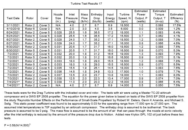
Participant@turbineguyI ran tests with Drag Turbine 4 and Drag Turbine 5 using the TC-95T airbrush compressor and the GWS EP 2508 propeller. The maximum speed for Drag Turbine 4 was 25,500 rpm with a corresponding power of 3.2 watts. The maximum speed for Drag Turbine 5 was 22,000 rpm with a corresponding power of 2.0 watts. Neither of these turbines exceeded the 3.4 watts I was able to obtain with Drag Turbine 3. Drag Cover 5 used on Drag Turbine 4 and Drag Turbine 5 with the nozzle intended to increase the power by having the flow enter in the direction of rotation only helped Drag Turbine 5. Maybe opening the nozzle size further might help Drag Turbine 4 since the nozzle throttles the flow and the mass flow might be reduced to a point that it reduces the power more than directing the flow in the right direction increases the power. I hesitate to open nozzles because once the material is removed, the nozzle bore can only get bigger unless a sleeve is used. In this case, there doesn’t appear to be a significant downside to trying a larger bore. I think I will try increasing the bore in tiny steps to see the effect on Drag Turbine 4 and Drag Turbine 5. The following table shown in the 04/07/2021 Post that shows what I tried with the TC-20 airbrush compressor. This table shows that the maximum power was with a nozzle size of 0.032” with Rotor 2 and Cover 5. The combination of Rotor 2 and Cover 5 is what I am calling Drag Turbine 4. I think I will find an optimum nozzle size for the TC-95T airbrush compressor the same way.
19 August 2021 at 20:48 #559026Turbine Guy
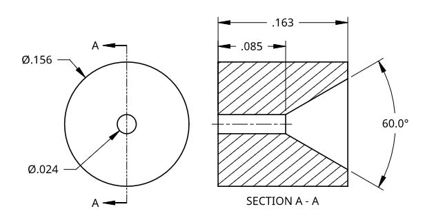
Participant@turbineguyThe first oversize of the Cover 5 nozzle changed the bore from 0.038” to 0.040” and dropped the maximum speed 500 rpm so increasing the nozzle bore size didn’t help. I made a nozzle shown in the following drawing and measured the maximum pressure my TC-95T airbrush compressor was able to supply for each change in bore size as shown in the chart below. I had done this for my airbrush compressor TC-20 and it allowed me to find the maximum energy available energy available. It turned out that the optimum nozzle size of Cover 5 was the size that gave the maximum available energy. When I did this with my TC-95T airbrush compressor it turned out that the nozzle sizes from 0.037” to 0.039” gave the maximum available energy so increasing the nozzle size to 0.040” decreased the available energy slightly. Apparently the 0.039” nozzle size gave the best performance I can get for Drag Turbine 4 using the TC-95T airbrush compressor and didn’t beat the performance of Drag Turbine 3.
20 August 2021 at 19:32 #559175Turbine Guy
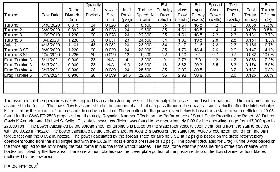
Participant@turbineguyAfter running the airbrush nozzle tests shown in the last post, I had enough information to update the table shown below to include the last tests of the drag turbines. This table was originally shown in the 09/04/2021 Post. Cover 5 and Rotor 5 never gave me the gain in performance I hoped I would get running on air with more mass flow. The Specific Speed, Ns, and the Specific Diameter, Ds, for the mass flow, enthalpy drop, turbine speed, and a rotor diameter shown for the 8/17/2021 test of Drag Turbine 3 are 2.4 and 7.1 respectively. For these values of Ns and Ds the efficiency of a optimum drag turbine shown in the Ns Ds Diagram in the 29/07/2021 post is approximately 33%. The actual efficiency as shown in the table below was 16.5%. I will look at the correction factors given by ‘A Study Of High Energy Level, Low Output Turbines’ prepared by Dr. O. E. Balje for the Department of the Navy in December 1957’ for the parts of the design that don’t meet the requirements in the next post.
21 August 2021 at 19:12 #559293Turbine Guy
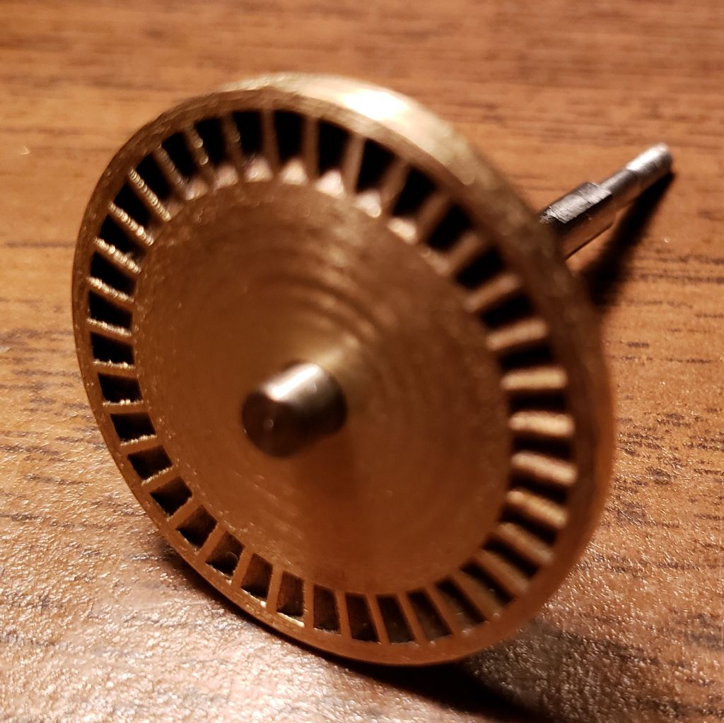
Participant@turbineguyThe first item I looked at on Drag Turbine 3 that didn’t meet the requirements of the study mentioned in the last post was the blade thickness. To meet the requirements, the blade thickness must be less than 0.2 times the flow channel effective depth. As shown in the picture above, the outer ends of the blades on Drag Rotor 2 have been wiped wider by the machining of the rotor face. Shapeways mentioned that one of the reasons they give a minimum thickness is to prevent this from happening. The blade thickness of Drag Rotor 2 was 0.009” and the minimum thickness recommended by Shapeways for Bronze is 0.024”. With the ends wiped wider, the flow blockage is worst than if I had made the blades 0.024” thick and used a rounded end like for Drag Rotor 4 shown in the picture below. The flow channel effective depth for Drag Cover 2 is 0.053” so the blade thickness needed to be 0.011” to meet the studies requirements. Assuming the effective blade thickness is 0.024” due to the wider ends, the blade thickness to effective channel depth ratio is 0.45”. The efficiency correction factor given by the study for this ratio is 0.73”. I will describe the efficiency correction for the excess leakage in the next post.
Edited By Turbine Guy on 21/08/2021 19:13:26
23 August 2021 at 18:51 #559558Turbine Guy
Participant@turbineguyI tried to use the efficiency correction given in the report mentioned in the 20/08/2021 Post but it didn’t appear to work for Drag Turbine 3. The report states the clearance between the rotor face and the cover needs to be less than 0.02 time the flow channel effective depth. The flow channel effective depth of Drag Cover 2 is 0.053” so the clearance needs to be less than 0.001”. I put the maximum number of shim washers that would still leave the rotor free to turn for the tests. When I tried adding one more shim washer the rotor was pressed tight enough against the cover that the pressure was the same as when I pushed the rotor flat against the cover plate. It appears that even though I have the required clearance, the flow leakage is still very high. The stall pressure with the 0.001” clearance necessary for running is approximately 11 psig. The stall pressure with the 0.001” shim added is approximately 15.5 psig. Since the TC-95T airbrush compressor has an air tank, it is capable of a higher mass flow for a few seconds than it can maintain continuously. I found that Drag Turbine 3 was able to run at a pressure of 15.5 psig for a very brief time and it was able to reach a speed of approximately 33,000 rpm turning the GWS EP 2508 propeller. This speed is quite a bit higher than the speeds I have the test results for, so I ran the APC 4 x 3.3 EP propeller. The APC 4 x 3.3 EP propeller reached a maximum speed of 6,750 rpm with a pressure of 15.5 psig for a very brief time. The power required by this propeller for this speed is approximately 1.9 watts. The maximum continuous speed with this propeller was 5,500 rpm with a pressure of 10.0 psig. The power required at this speed is approximately 1.0 watts. The available power for 15.5 psig is approximately 25.0 watts resulting in an efficiency of 7.6%. The available power for 11 psig is approximately 22.6 watts resulting in an efficiency of 4.5%. The efficiency correction for leakage should be approximately the ratio of the efficiencies 4.5/7.5 = 0.6. With this 0.6 correction for leakage and the 0.73 correction for blade thickness, the 33% estimated efficiency given by the Ns Ds Diagram mentioned in the 20/08/2021 post is reduced to 14.5%. The actual efficiency for the test being considered was 16.5% so the correction factors I came up with are too conservative. I am going through all this to show what parts of the design of Drag Turbine 3 are causing its performance to be less than predicted for a design meeting all the requirements. I can’t reduce the thickness for the blades so the correction factor for blade thickness will remain the same. I can’t reduce the clearance between the rotor face and the cover plate so the correction for leakage will also remain the same.
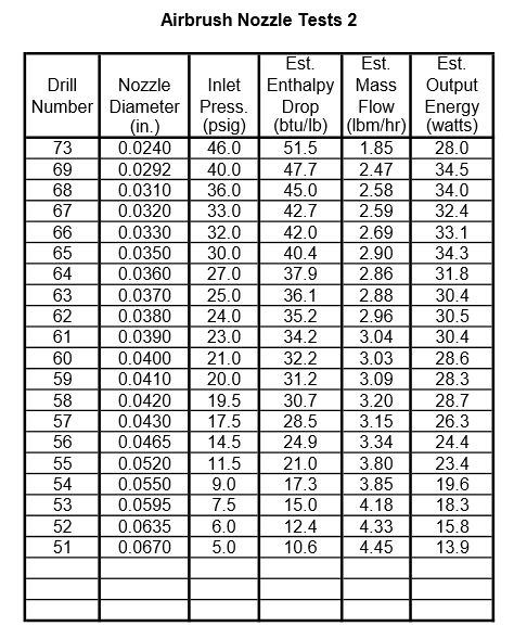
What has been shown by these tests, is that the amount of power I can make using the TC-96T airbrush compressor is larger than my GWS EP 2508 propeller can absorb. I am going to make a series of tests with all my turbines to find the pressure required to spin the GWS EP 2508 propeller to a speed of 28,000 rpm. With these pressures found, I will be able to use the airbrush nozzles test chart shown in the 19/08/2021 post to calculate the efficiency for each design.
26 August 2021 at 18:53 #559948Turbine Guy
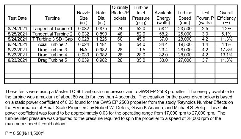
Participant@turbineguyTo find the maximum power with each of my turbines using my TC-96T airbrush compressor, I pinched the air hose closed and let the pressure raise to the shut off point of 60 psig in the air tank. I then suddenly opened the air line and measured the air pressure where the turbine ran at a speed of 28,000 rpm if this speed could be reached. If the 28,000 rpm could not be reached, I recorded the speed obtained and the air pressure at that speed. The air tank could only supply this air pressure for a few seconds. The following table shows the test results for each of my turbines. Each turbine type used the same ball bearings which were removed from one turbine reoiled with Krytox GPL 102 oil and put in the turbine tested next. Because the temperature is reduced when the air expands in the turbines the temperature is less than ambient, so the viscosity stays relatively high. The Aero Shell Fluid 12 oil that comes with the ball bearings I use is lower viscosity, but I have not found a source for this oil in small quantities. Since these ball bearings are getting very difficult to purchase, I need to add oil regularly to extend their life and the Krytox GPL 102 oil is the best replacement I have found. To measure the loss in power due to using the higher viscosity oil, I measured the speed of Drag Turbine 3 with a GWS EP 2508 propeller and new ball bearings and then with the new bearings reoiled with Krytox GPL 102 oil. The maximum speed dropped from 15,000 rpm to 10,500 rpm. The power required for the GWS EP 2508 propeller for a speed of 15,000 rpm is 0.6 watts and for a speed of 10,500 rpm is 0.2 watts. A loss of power of approximately 0.4 watts. Tangential Turbine 3 SD + Gap, Drag Turbine 3, Drag Turbine 4, and almost Drag Turbine 5 were able to reach the speed of 28,000 rpm without the maximum available energy. Tangential Turbine 1 and Tangential Turbine 2 were not able to reach 28,000 rpm even with the maximum available energy. The Drag Turbines required the least amount of available energy to reach this speed.
2 September 2021 at 16:22 #560941Turbine Guy
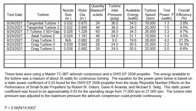
Participant@turbineguyI ran another set of tests with my turbines like those in the last post but finding the power that could be maintained continuously with the TC-96T airbrush compressor. The following table shows the results of these tests. Drag Turbine 3 appeared to be improving each time I ran it, so I kept making short runs with it until it appeared to be completely bedded in. The results for Drag Turbine 3 shown in the table were added after making the multiple short runs and adding new oil like was done for the tests of the other turbines. This turbine outperformed all the other turbines with the TC-96T airbrush compressor so I ran it for several short tests without reoiling the bearings to see what speed the turbine could reach after the oil thinned out. The maximum speed turning the GWS EP 2508 propeller was 29,500 rpm. The power required by the propeller for that speed is approximately 4.9 watts so there was a gain in power of approximately 0.7 watts. This variation in performance with the condition of the oil is why it is so important to have the condition of the oil the same for any comparison tests. Both the following table and the table shown in the last post had all the tests with oil just added so the efficiency will only get better until the oil gets too thin or wears out.
3 September 2021 at 20:56 #561131Turbine Guy
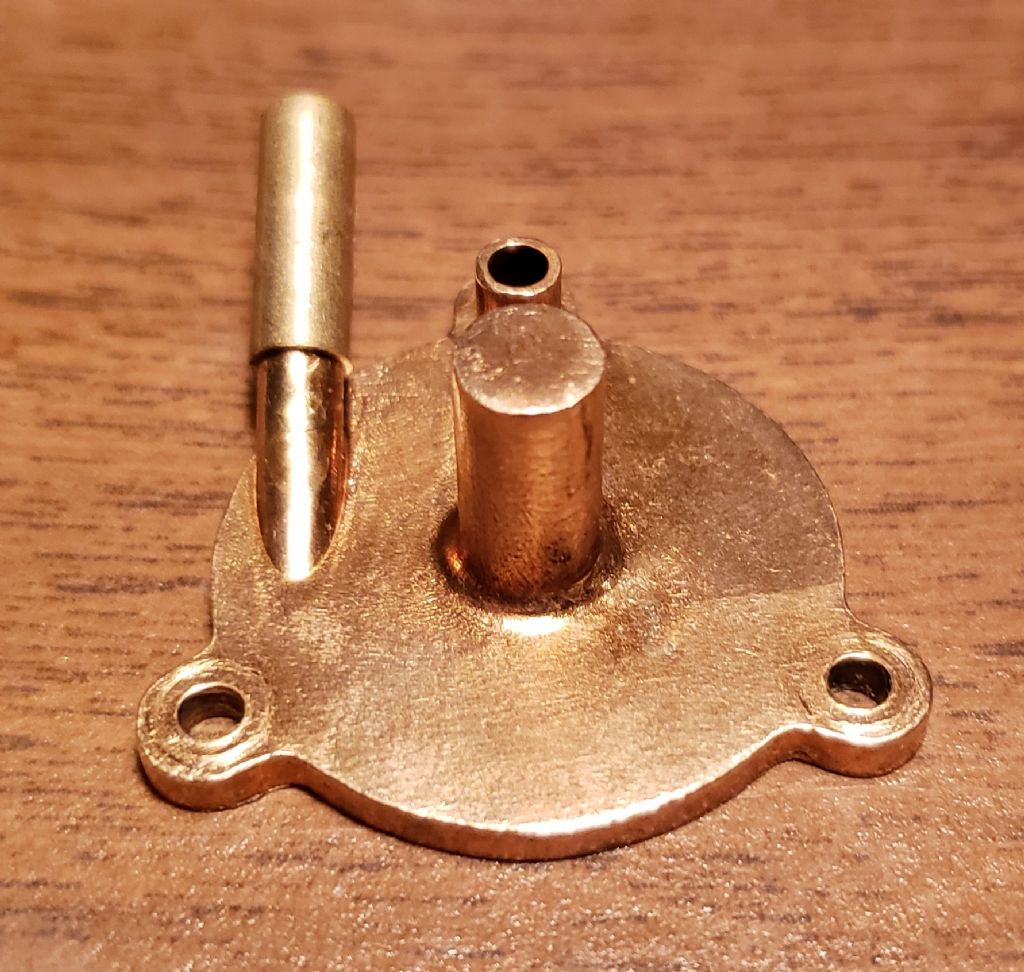
Participant@turbineguyAfter seeing the improvement of Drag Turbine 3, I ran Drag Turbine 4 that only the cover is different. After reoiling the bearings, it reached a speed of 28,000 rpm turning the GWS EP 2508 propeller. After several short runs the maximum speed started to go over 30,000 rpm so I reoiled the bearings and the maximum speed was 28,000 rpm. Drag Turbine 4 gave me the best performance of all my turbines running on the TC-96T airbrush compressor. Cover 5 added the nozzle directed in the flow direction that I thought would help, but in previous tests did not work as well as Cover 3. I tried to run Drag Turbine 5 to see if the breaking in helped it. I couldn’t keep the airline from blowing off. The hose clamp was tightened until it bottomed out and the hose would still blow off before a pressure of 20 psig could be reached. I cut off the end of the airline where it had been clamped and the hose clamp still bottomed out and the hose blew off. The inlet tube is too short and has a smaller OD than needed. I used Loctite to add a longer and larger OD extension as shown in the picture below. I will try running the drag turbines again tomorrow after the Loctite has fully cured.
Edited By Turbine Guy on 03/09/2021 21:01:01
4 September 2021 at 20:06 #561263Turbine Guy
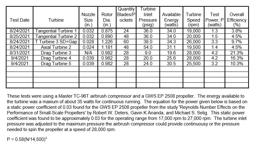
Participant@turbineguyI ran Drag Turbine 4 and Drag Turbine 5 after adding the sleeve to the inlet tube of Cover 5. The larger diameter and extra length allowed the hose clamp to fully tighten and the pressure to reach it’s maximum without leakage. The following table was updated to show the latest test results. Even with the bearings just oiled, Drag Turbine 4 was able to spin the propeller at a speed of 28,000 rpm with a 20 psig pressure. The speed of the propeller went over 30,000 rpm before the 24 psig the airbrush compressor is capable of continuously was reached. With the right load this turbine could produce over 5 watts with the TC-96T airbrush compressor. Drag Turbine 4 is capable of producing the most power but Drag Turbine 3 is more efficient and better suited to energy sources capable of high mass flows at low pressures.
9 September 2021 at 19:47 #562103Turbine Guy
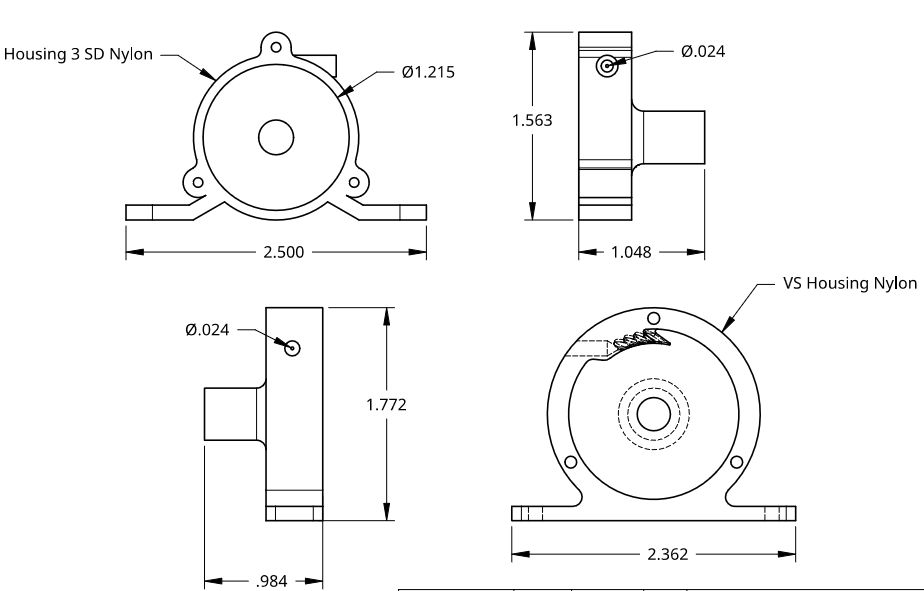
Participant@turbineguyOne of the reports I read mentioned that they made their prototypes from plastic until they found their optimum designs. This cuts the cost down considerably and probably the amount of machining time. I haven’t machined any plastics for a while, so I am only guessing they are easier to machine. Shapeways uses a laser to sinter nylon powder into plastic layer by layer that uses SLS technology to print the PA11 nylon. Since the PA11 nylon is unaffected by the Kryox GPL 102 and 105 oils I use for my turbines, I ordered a couple of housings shown in the following drawing. I decided to try housings for my first plastic parts since they are the most expensive bronze castings. The cost of Housing 3 SD for nylon is approximately $20 and for bronze is approximately $180. The cost of the VS Housing for nylon is approximately $25 and for bronze is approximately $300. The Housing 3 SD is designed to be used with all the other parts of Tangential Turbine 3 SD. The VS Housing has 4 blades that circulate the flow back into and out of the rotor like used by Terry turbines. This is something that I have wanted to try and is beyond my machining capabilities. I picked the PA11 nylon since the minimum thickness was even smaller than for bronze (0.5 mm vs 0.6 mm). If Shapeways printed housings hold the tolerances tight enough and the plastic is strong enough to use these housings for my turbines, it will allow me to try many more options. The dimensions on the following drawing were intended to be used to check if Shapeways had the step files scaled correctly. Shapeways did not mention any shrinkage for the printing so I will check the accuracy of the parts by showing the actual dimensions in parenthesis next to design dimensions after I receive the parts.
21 September 2021 at 18:18 #563754Turbine Guy
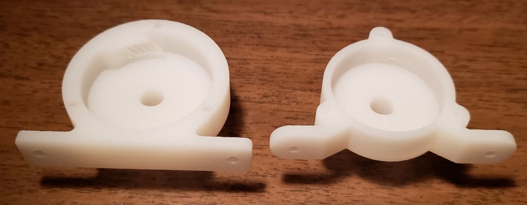
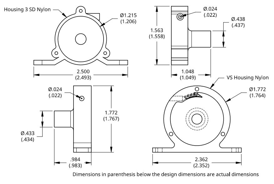
Participant@turbineguyI received the printed housings as shown in the following photo. I measured the housings, and the following drawing shows the design dimensions with the actual dimensions below them in parenthesis. The housings appeared to be stiff enough and strong enough to work running on air. The details of the velocity staging in the VS Housing Nylon looked very good and would be very difficult to machine. The printing process leaves a rough finish, and I am hoping the machining needed to make the critical dimensions will leave a smooth surface. I will start the machining on Housing 3 SD Nylon first and give updates as the progress continues.
23 September 2021 at 14:15 #563995Turbine Guy
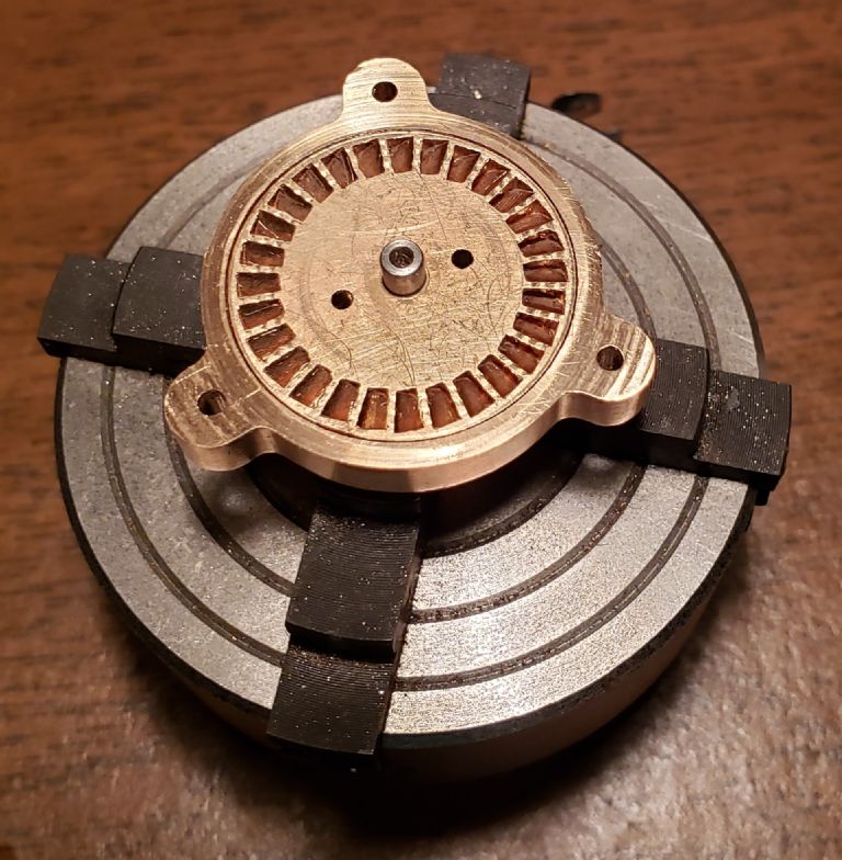
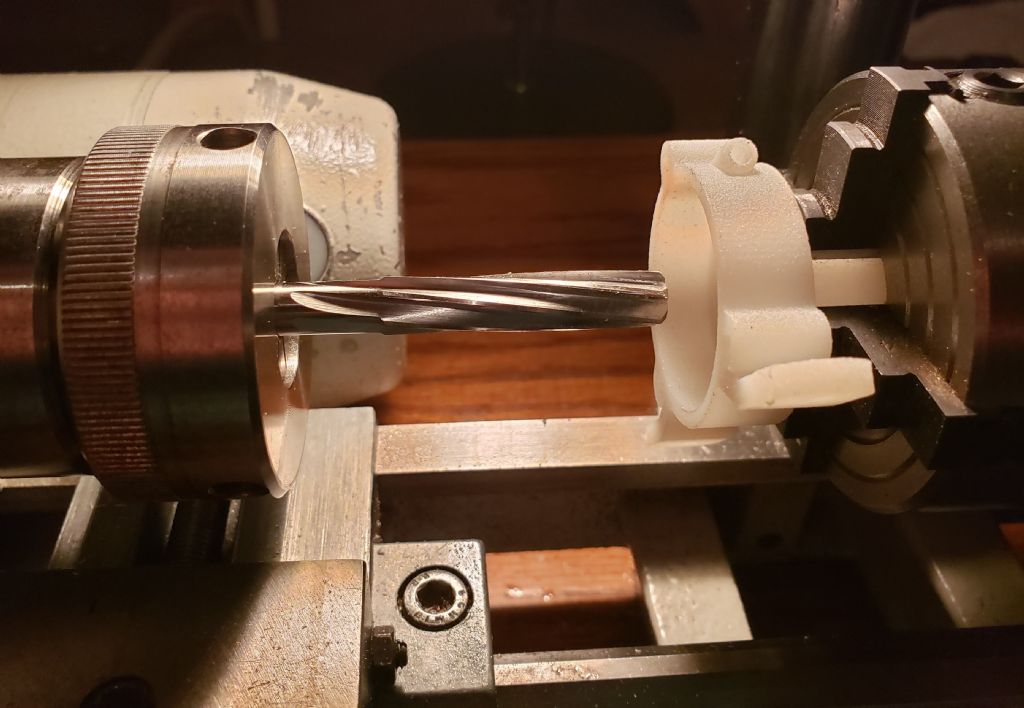
Participant@turbineguyI started the machining of Housing 3 SD Nylon by centering it in the 4 jaw chuck and reaming the bore for the ball bearings as shown in the following photo. I used the smallest change in drill sizes progressing up to just a little smaller than the reamer size. The jump from a K (0.281) to an L (0.290) drill size caused the housing to move in the 4 jaw chuck. I centered the housing again and tightened the jaws a little tighter and had no further problems. I hope that I didn’t lose much accuracy after needing to re-center the housing. The ball bearing took a light push fit to enter the exposed end. A dowel pin the same OD as the ball bearing had a tight slip fit all the way through the bore. I kept the dowel pin in the bore and tightened the 4 jaw chuck a little more before machining the rotor bore and housing faces. The machining of the rotor bore and housing faces was very easy and the finish quite smooth. The problem of gripping the extension of the housing could be helped by making the OD larger. When the ball bearing bore is machined to full size, the wall thickness of the extension is too small for nylon. I made the housing with minimum wall thickness for casting in bronze to reduce the cost. Extra thickness doesn’t add much cost when printing nylon and would be an improvement.
Edited By Turbine Guy on 23/09/2021 14:19:26
30 September 2021 at 15:40 #564888Turbine Guy
Participant@turbineguyI finished all the machining of Housing 3 SD Nylon. Everything was fine until I tried opening the hole the inlet tube slides into. My setup for opening the hole apparently was not rigid enough and the drill wandered enough to break through. Because of this, I can’t use the nozzle. I thought that I would try using this housing with Axial Rotor 2 instead of the aluminum housing. When I opened the bore enough that Axial Rotor 2 had enough clearance the wall thickness became too thin. The slightest pressure on the OD of the housing caused contact with the rotor. I believe this makes the housing not rigid enough to try mounting the Axial Nozzle plate and running as an axial impulse turbine. I still believe that if the wall thickness is enough, the nylon housing will work fine. I am in the process of designing a new housing and nozzle plates made of nylon that will be stiff enough to work with Axial Rotor 2 and Tangential Rotor 3 SD. These parts will be designed based on what I have learned from machining Housing 3 SD Nylon.
12 October 2021 at 14:33 #566566Turbine Guy
Participant@turbineguyBecause I have tried so many different turbines and combinations of parts, it is difficult to tell from a brief description what the configuration includes in the turbine test results. To try to make this a little clearer, I have started to make individual albums for each configuration. If you are curious what the parts look like and/or want to see the drawings you can open the applicable album. This is a work in progress and I have only got the axial and tangential turbines started. I will also add albums for the drag turbines and any new turbines. Hopefully this will make it a little clearer what I am testing.
Edited By Turbine Guy on 12/10/2021 14:35:53
21 October 2021 at 19:05 #567637Turbine Guy
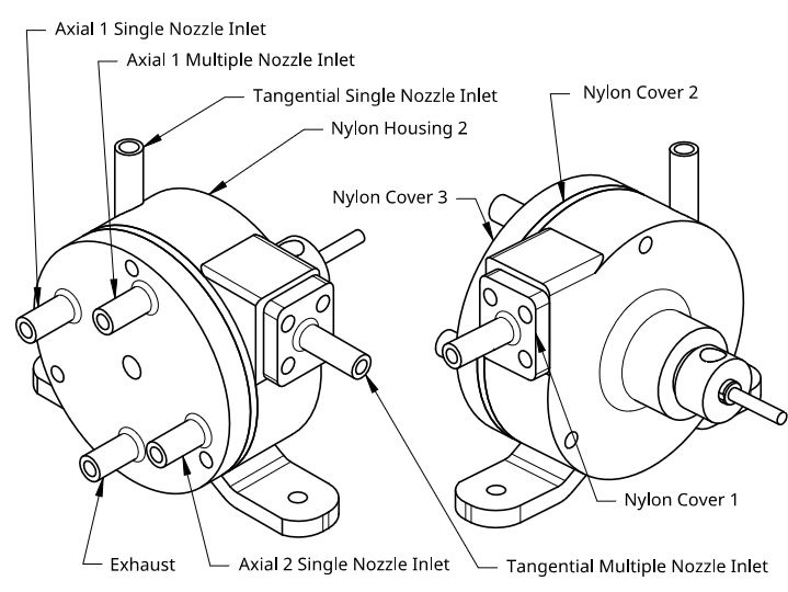
Participant@turbineguyI ordered the parts shown in the following drawing made of printed nylon from Shapeways. The designs met Shapeways requirements and the parts have been printed and shipped. These parts will give me a little more experience in printed nylon and allow me to try several things. As shown on the drawing there are inlet ports for two different axial impulse rotors and one tangential impulse rotor. The inlet ports shown as Axial 1 will be used for running my existing Axial Rotor 2 shown in the Axial Turbine 2 Album. The inlet ports shown as Axial 2 will be used with an axial rotor that will be made later. The inlet ports labeled tangential will be used with my existing Rotor 3 SD shown in my Tangential Turbine 3 album. I plan to compare the performance of the single nozzles made of nylon with those made of aluminum. I will also compare the performance of the single nozzles that will run supersonic to the multiple nozzles running subsonic. The new axial rotor will use a single nozzle large enough to run subsonic so I will be able to compare the single large nozzle with multiple smaller nozzles.
26 October 2021 at 19:34 #568377Turbine Guy
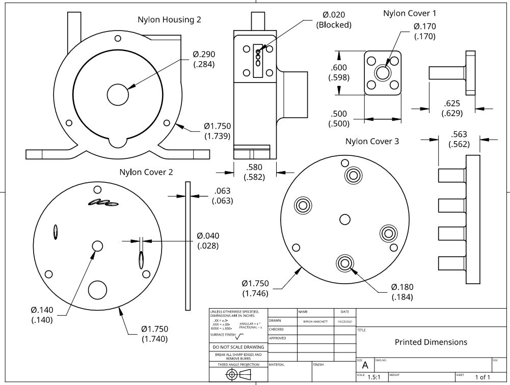
Participant@turbineguyThe following drawing shows the design dimensions with the actual as printed dimension below in parentheses for the parts of the Nylon Turbine. Only a few dimensions on each part are shown to illustrate the accuracy of the printed nylon parts from Shapeways. None of the holes with a design diameter of less than 0.040” went all the way through. Housing 3 SD Nylon had a nozzle hole with an design diameter of .024” that had an actual printed dimension of 0.022” diameter that went all the way through. The description and drawing of Housing 3 SD Nylon is shown on the 21/09/2021 Post. The overall accuracy of these printed parts was quite a bit lower than on Housing 3 SD Nylon. Even a needle with a sharp point would not enter either accessible end of the smaller holes. The accuracy given by Shapeways for PA 11 printed nylon is +/- 0.3mm, +/- 0.012", so I expected way too much for the small diameters and closely spaced holes. I will have to decide what I can do with these parts. Without the holes going through all the way, I can’t open them up while using them to guide the drill as planned. Also the placement of the nozzles will require more accuracy than Shapeways tolerance will allow. The increased wall thickness of the housing will allow me to machine it without it deflecting too much but the thin walls of the inlet and outlet tubes do not look strong enough. The next post will show photos of these printed parts.
Edited By Turbine Guy on 26/10/2021 19:36:31
Edited By Turbine Guy on 26/10/2021 19:38:10
26 October 2021 at 19:40 #56838026 October 2021 at 20:57 #568393Turbine Guy
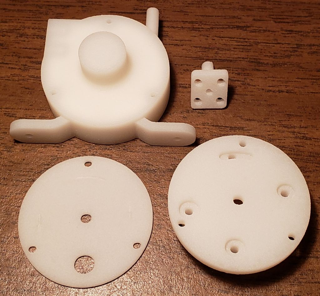
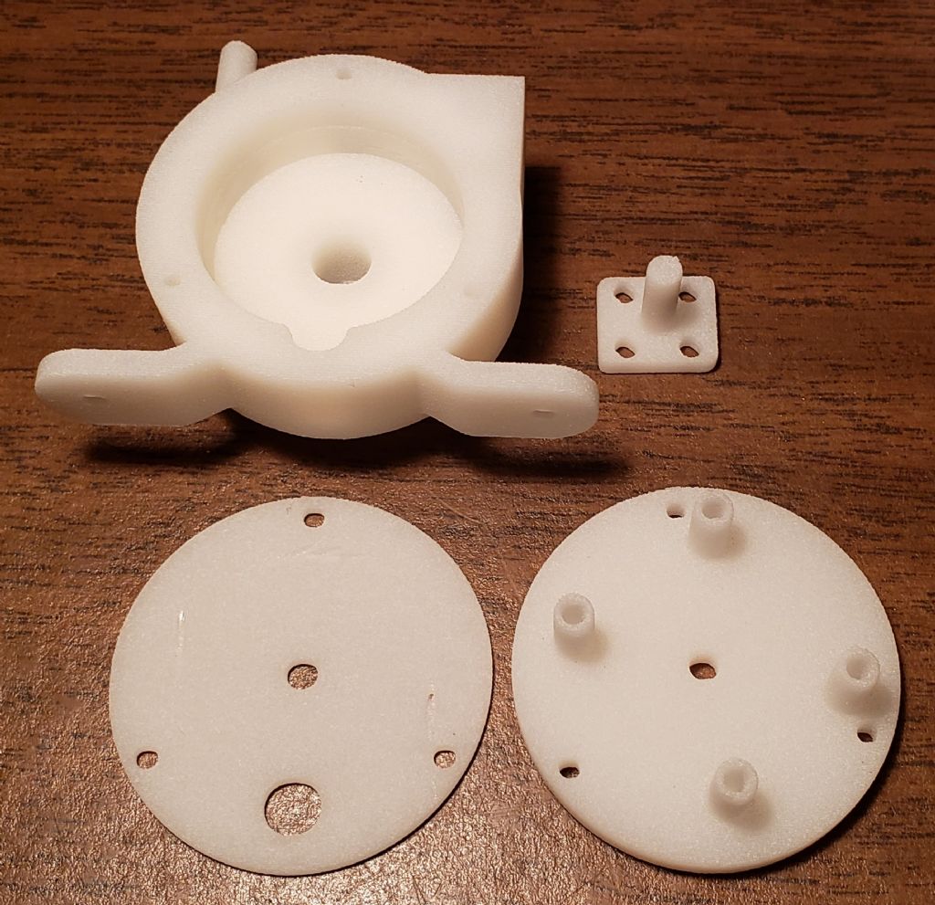
Participant@turbineguyThe following photo is of Nylon Cover 2 tilted at an angle where the angled nozzle holes are a little easier to see. The reflection of the nylon makes it difficult for me to show how much of the nozzle holes was printed. Even though the smaller holes didn't get to the correct size or go completely through, they were partially made and in approximately the right places. I think if the design takes into account the limits of the printing process, the printed parts can be very useful.
29 October 2021 at 20:30 #568878Turbine Guy
Participant@turbineguyI decided to go ahead and machine Nylon Housing 2 to where it could be used for axial rotors since the nozzle holes for the tangential rotor were not useable. It required approximately 0.008” removed from the faces for cleanup. I enlarged the bore for the rotor to approximately 1.250” to give a total clearance of 0.005” (0.0025” per end) with the new 1.245” OD rotor I plan to use in this housing. This diameter gives enough clearance for the shrouded axial rotors given to me by Werner Jeggli as shown in the following photo. I used his printed rotor since I was able to center it the best on the shaft and I wanted to see if the clearance was about the same all around. I also wanted to show how little material needed to be removed to balance the rotor. My photo of his cast rotor shown in my Axial Turbine 2 album required a lot of extra material be removed for balancing since it was off center a few thousandths. Even being off center it out performed the printed rotor due to the much smoother surfaces of the blades. With the extra wall thickness of this housing there was no slippage in the 4 jaw chuck during all the machining and the reamed hole for the ball bearings was a very light press fit on both ends. All the machining took only a few hours to finish the housing and the bores remained concentric and perpendicular to the faces. This housing should work well for testing the axial rotors.
I think I will be able to run the new axial rotor using Nylon Cover 2 and Nylon Cover 3, but I plan to make a cover plate similar to what I used on Axial Turbine 2 to compare the performance with the type of nozzle I have used on all my other turbines. The two covers type of nozzle could be very useful for closely spaced multiple nozzles if the nozzle efficiency is high enough.
31 October 2021 at 20:19 #569170Roger Best
Participant@rogerbest89007Looks good, not as pretty as brass but great for progress.


-
AuthorPosts
- Please log in to reply to this topic. Registering is free and easy using the links on the menu at the top of this page.
Latest Replies
Home › Forums › Stationary engines › Topics
-
- Topic
- Voices
- Posts
- Last Post
-
-
Twin Engineering’s heavy mill/drill quill removal
Started by:
Martin of Wick in: Manual machine tools
- 8
- 16
-
2 July 2025 at 21:54
Martin of Wick
-
Pattern Makers Vice
Started by:
 Vic
in: The Tea Room
- 7
- 9
-
2 July 2025 at 21:51
 KEITH BEAUMONT
-
J&S grinder – belt which way ?
Started by:
gerry madden in: Manual machine tools
- 7
- 9
-
2 July 2025 at 21:44
not done it yet
-
Meddings MF4 Manual
Started by:
Richard Kirkman 1 in: Help and Assistance! (Offered or Wanted)
- 11
- 23
-
2 July 2025 at 21:38
Richard Kirkman 1
-
Haining vertical dairy engine boiler.
Started by:
apprentice in: Beginners questions
- 3
- 7
-
2 July 2025 at 20:52
 JasonB
-
Speed camera
1
2
Started by:
 David George 1
in: The Tea Room
- 20
- 39
-
2 July 2025 at 20:01
Plasma
-
Injectors
Started by:
pansy123 in: General Questions
- 3
- 4
-
2 July 2025 at 17:56
pansy123
-
Motor won’t start
Started by:
Rowan Sylvester-Bradley in: Beginners questions
- 9
- 9
-
2 July 2025 at 17:30
larry phelan 1
-
IME Watchmakers lathe
Started by:
Greensands in: Manual machine tools
- 11
- 16
-
1 July 2025 at 21:41
Dave S
-
Request for a Slot to be Milled in a Shaft
Started by:
James Alford in: Help and Assistance! (Offered or Wanted)
- 9
- 18
-
1 July 2025 at 21:03
bernard towers
-
Bearing boxes for ball race
Started by:
Paul McDonough in: Beginners questions
- 9
- 17
-
1 July 2025 at 21:02
Paul McDonough
-
The Stevenson Trophy – Entries Invited
Started by:
 Neil Wyatt
in: Website Announcements
- 1
- 2
-
1 July 2025 at 18:44
 Neil Wyatt
-
The Bradford Cup – Nominations Wanted
Started by:
 Neil Wyatt
in: Website Announcements
- 1
- 2
-
1 July 2025 at 18:41
 Neil Wyatt
-
FreeCAD v1.0 tutorials
1
2
3
Started by:
 Michael Gilligan
in: CAD – Technical drawing & design
- 12
- 54
-
1 July 2025 at 18:31
Speedy Builder5
-
All things Beaver Mill
1
2
…
8
9
Started by:
Robert James 3 in: Manual machine tools
- 43
- 208
-
1 July 2025 at 18:22
Charles Lamont
-
Dial test indicator vs Dial indicator
Started by:
martian in: Workshop Tools and Tooling
- 17
- 24
-
1 July 2025 at 16:59
Clive Foster
-
Help for DIY lathe build.
1
2
Started by:
moogie in: Help and Assistance! (Offered or Wanted)
- 16
- 32
-
1 July 2025 at 15:21
David Senior
-
Firth Valve Gear
Started by:
Andy Stopford in: Traction engines
- 9
- 18
-
1 July 2025 at 12:59
Nigel Graham 2
-
M type top slide conversion??
Started by:
jimmyjaffa in: Beginners questions
- 7
- 11
-
1 July 2025 at 11:35
 David George 1
-
Offen screw type telescopic gauge.
Started by:
Graeme Seed in: Workshop Tools and Tooling
- 4
- 9
-
1 July 2025 at 10:41
Graeme Seed
-
2 Machine lights
Started by:
modeng2000 in: Workshop Tools and Tooling
- 2
- 6
-
1 July 2025 at 08:57
Dalboy
-
New member looking for help
Started by:
 manfromthemist
in: Introduce Yourself – New members start here!
- 11
- 24
-
1 July 2025 at 08:19
Juddy
-
Wiring up a single phase AC motor with 4 wires
Started by:
ell81 in: Beginners questions
- 6
- 8
-
30 June 2025 at 19:49
Howard Lewis
-
New (old!) member
Started by:
iansoady in: Introduce Yourself – New members start here!
- 3
- 3
-
30 June 2025 at 19:30
Howard Lewis
-
Boiler Design – issue 4765
1
2
…
7
8
Started by:
Charles Lamont in: Model Engineer & Workshop
- 26
- 178
-
30 June 2025 at 12:58
Paul Kemp
-
Twin Engineering’s heavy mill/drill quill removal
-


