Model Turbines
Model Turbines
Home › Forums › Stationary engines › Model Turbines
- This topic has 599 replies, 28 voices, and was last updated 22 April 2025 at 21:59 by
Turbine Guy.
-
AuthorPosts
-
17 January 2021 at 20:55 #520558
Turbine Guy
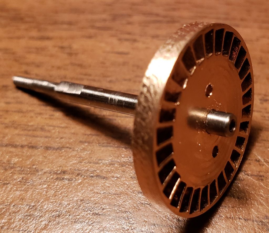
Participant@turbineguyI finished Drag Rotor 2 as shown in the following photo. Machining the rotor would have been very easy if I had done all the machining with the cast rotor not taken out of the chuck until all the critical machining was finished. Holding the cast rotor by the round part that extended from the back face of the rotor allowed enough room to machine both faces and the OD to their final dimension after reaming the bore. Because I got what I thought would be a strong enough press fit, I decided to cut off the excess length of the extension and then press fit the rotor to the shaft for the final machining. My hacksaw slipped while cutting off the extension and I ended up with not enough length of the hub to run a pin through. I had to rely on the press fit of the rotor without most of the hub. This gave enough strength to machine the front and back face of the rotor but the wave in the OD caused enough force to break the press fit. The holes added were for pins I used to go through the rotor and into a clamping collar that gave me enough grip to turn the OD. I then used part of the cut off extension that had the reamed hole to make a collar the right length to get the hub back to it’s intended length. I ended up with rotor and shaft machined to the dimensions I needed but could have saved myself a lot of work. The cast housing and end plate have been shipped from Shapeways and will arrive soon. Hopefully, I will do a better job with them.
Edited By Turbine Guy on 17/01/2021 21:14:29
20 January 2021 at 15:15 #521307Turbine Guy
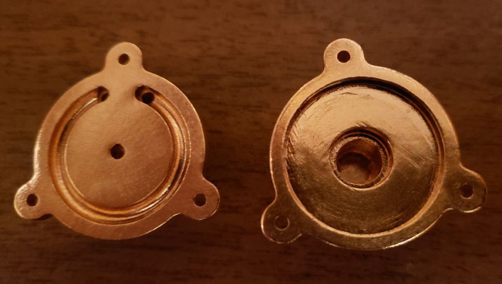
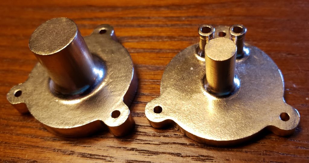
Participant@turbineguyThe castings for the Drag Turbine 3 Housing and Cover arrived and are shown in the following photos. They came in jewelry bags like the rotor casting. Before setting these up for machining, I made a few measurements to check the shrinkage. The drawing showing these dimensions will added in the next post. Overall, the castings looked very good, and when the cover is placed on the housing all the holes and edges line up nicely. I opted for a natural finish, so the cleanup might have polished some of the surfaces.
20 January 2021 at 16:24 #521317Turbine Guy
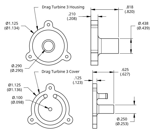
Participant@turbineguyThis is the drawing mentioned in the previous post. The upper dimension is the size that would be obtained by a uniform 2% shrinkage. The lower dimension in parenthesis is the actual measured dimension. Each actual measured dimension was taken in several places and the average was used. This should give a reasonable indication of what to expect assuming 2% shrinkage with these types and sizes of bronze castings. As can be seen in the drawing the actual shrinkage varies. The worst deviation was on the wide thin portion, the OD of the housing and cover flanges. These dimensions were from 0.009” to 0.011” larger than they would be with a perfect mold and uniform 2% shrinkage. All the other measured dimensions were within +/- 0.003”, which is excellent in my opinion.
22 January 2021 at 19:39 #521861Turbine Guy
Participant@turbineguyAfter reading about the accuracy of drill chucks I decided to see if I could get a collet holder (chuck) for my Unimat 3. I couldn't find any source in the USA so I made the following thread Unimat 3 Collets. Several people helped me in my decision of what to purchase and I ordered a set of collets that included a collet holder from ebay UK. Anyone with a Unimat 3 and thinking about getting collets may find this thread useful. Since this set is coming from the UK, it will be a few weeks before I can start the machining on the Drag Turbine 3 Housing and Cover. To get the maximum performance with the Drag Turbine, the clearances must be made as small as possible. I thought using collets could help with the reaming of the bearing bores and with centering the cast parts in the 4 jaw chuck.
2 February 2021 at 14:02 #524319Turbine Guy
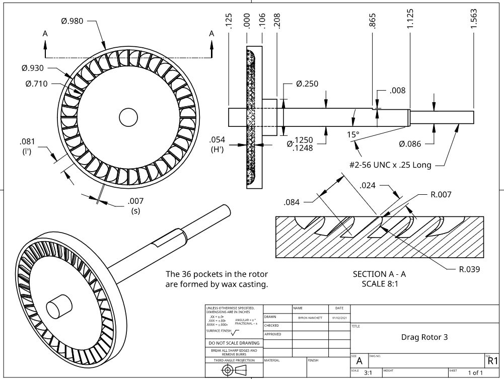
Participant@turbineguyWhile waiting for my collet set to arrive, I made the following changes to Drag Rotor 3 shown in the drawing below. I cleaned up my method of forming the blades to utilize the options I have with castings. Instead of modifying the solid model made for machining the rotor with a keyway cutter, I designed the blades from the start for casting. I also changed the end of the blades from 0.3mm radius to a 0.18mm radius with a 1mm radius lead in edge. As you can see from the drawing, the 0.6mm thickness must be used for most of the length of the blade. Shapeways allows a minimum thickness of 0.35mm providing the length is no longer than 0.35mm. I was also able to reduce the maximum blade depth H’ to its optimum value. This allowed me to increase the number of blades. These changes should help if I decide to try another rotor.
3 February 2021 at 13:39 #524517Turbine Guy
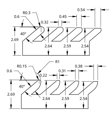
Participant@turbineguyThe following drawing shows the advantage of the smaller radius at the tip of the blade when cleanup of the casting is required. When the face of the rotor is machined, a flat is formed at the end of the blades. The more the face is machined, the wider the flat becomes. The drawing dimensions are in millimeters and the blades are shown as if they were running in a straight line. The top set of blades is with the 0.3mm radius I originally planned to use on Drag Rotor 3 as shown in the post of 06/01/2021. The bottom set of blades is what is shown on the drawing of the preceding post. I show the amount being taken off the face in 0.05mm increments as the blades proceed from left to right. The width of the flat on the existing Drag Rotor 2 is 0.38mm so only a little over 0.05mm can be taken off the 0.3 radius without exceeding this. Up to 0.15mm can be taken off the 0.15 radius without exceeding the flat width of the existing blades. The efficiency of the drag turbine is reduced significantly if the flat gets too wide so the minimum amount of cleanup of the face of the rotor should be used.
9 February 2021 at 16:44 #525948Turbine Guy
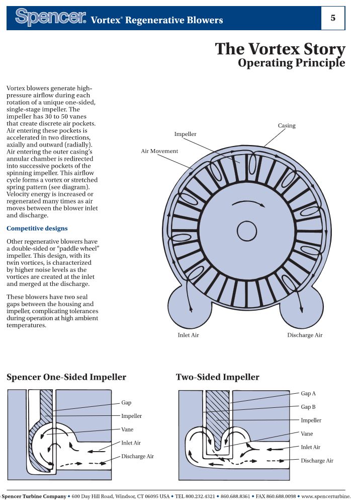
Participant@turbineguyI read through the section on Drag Turbines again in ‘A Study of High Energy Level, Low Power Output Turbines’ done for the Office of Naval Research in 1957. This study concluded that the increased drag on the rotor was due to the corkscrew rotation of the flow into the bottom of the blades and out of the top of the blades into the flow channel as discussed in the 09/12/2020 post in this thread. This study also stated that the drag coefficients were independent of the rotor speed that had been confirmed with tests of the stall torque. I designed Drag Turbine 3 based on the concept used by Spencer in their Vortex Regenerative Blowers as shown in the 09/12/2020 post and below. I thought that the Spencer concept would increase the rotation of the gas due to the flow being guided back into the flow channel by a radius rather than being discharged onto a flat surface like shown for the two-sided impeller. The two-sided impeller was the type used in the study and the drag coefficients were developed for. If the corkscrew rotation of the flow is what causes the higher rotor drag coefficient and the rotor drag coefficient is independent of rotor speed, the corkscrew flow must be established even with the rotor stationary. Comparing the one-sided and two-sided impellers, I can see that any flow from the stationary channel that enters the two-sided impeller is guided towards the OD of the impeller. This would start the flow moving in a corkscrew direction even with the impeller stationary. For the one-sided impeller, any flow from the stationary channel that enters the impeller is guided toward the center of the blades when the impeller is stationary. I assumed that the centrifugal force would start the flow moving out the outer part of the blade when the rotor got to the higher speeds and provide the necessary circulation. In the next post I will show a source with test results for these two concepts.
10 February 2021 at 18:43 #526230Turbine Guy
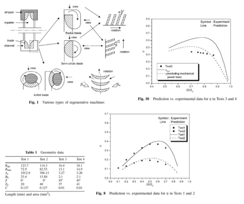
Participant@turbineguyThe following figures and table are copied from ‘A modified theory for the flow mechanism in regenerative flow pump’ by J. W. Song, A Engeda, and M. K. Chung from the proceedings of the Institution of Mechanical Engineers, Part A: Journal of Power and Energy 2003 found at this Link. The best efficiency for the radial blades like used in Dr. Balje’s reports is shown in Fig. 8 Test 2. The best efficiency for the semi-circle blade like my Drag Turbine 3, is shown in Fig.10. Table 1 gives the dimensions of these pumps. Rtip is the radius to the tip of the blade or channel, Rhub is the radius to the hub of the blade or channel, Ac is the area of flow channels, Bb, is the effective width of the blade channel, β is the blade angle, Zb is the number of blades, and C is the clearance. Q/Qs is the ratio of the flow to the solid rotation flow. You can see from the figures that the peak efficiency of the semi-circle blades is slightly higher, but the estimated performance of the radial blades is much closer to the test values.
Edited By Turbine Guy on 10/02/2021 18:47:16
20 February 2021 at 17:11 #528908Turbine Guy
Participant@turbineguyThe collet set I ordered finally arrived. The runout of the collet holder was so bad I had to request a refund. I got a full refund from the seller and found another Ebay seller located in the USA that had a collet set with a genuine EMCO collet holder. I ordered that collet set and it should arrive within a week. When it arrives, I will finally be able to start the machining on the Drag Turbine 3 housing.
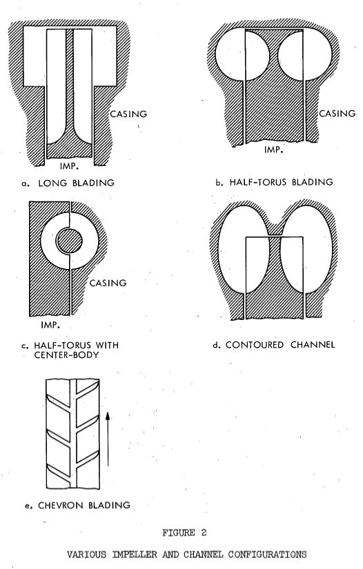
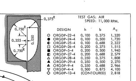
In the meantime, I found another article ‘A STUDY OF THE PERIPHERAL COMPRESSOR’ by Phillip Cates issued August 26, 1966 at this link Peripheral Compressor. Since this study deals with gases rather than liquids, it might be a better example of what to expect with semi-circular blades. The following figures copied from page 4 of this study shows the type of blading that was reviewed. Page 37 described what was found from the analysis and testing of a pump with the type of blades shown in Figure 2(b). The maximum overall efficiency for this type of blading was given as 46% when tested with a liquid. Page 111 showed the dimensions for a contoured blading that gave the best efficiency of any of the long blading shown in Figure 2(a). The maximum efficiency was given as 41% from testing with air. Tests with pumps typically show higher efficiency than tests using gases, but the half-torus blading appears to be quite effective.
21 February 2021 at 18:05 #529187Turbine Guy
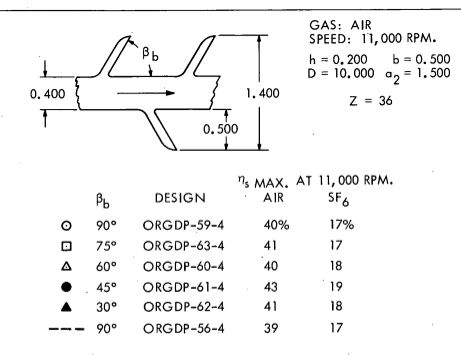
Participant@turbineguyThe attached figure shows the contoured blading that gave the best efficiency of the long blading discussed in the last post. The tests with the Chevron blading (Figure 2(e) in the last post) showed a maximum efficiency of 43% with blade angles of 45 degree. The maximum efficiency for 90 degree blades from these same tests was 40%. This confirmed Balje’s findings that the optimum efficiency was with blade angles from 40 to 45 degree, but had much less difference in efficiency with 90 degree blades as shown in the following table.
 23 February 2021 at 16:04 #529586
Turbine Guy
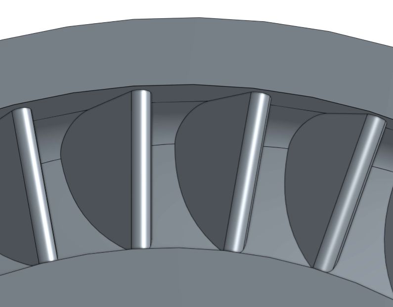
Participant@turbineguyThe following picture shows the changes to the blades of Drag Rotor 3 in revison 2. I am trying to optimize Drag Rotor 3 based on everything I learn before making a casting. The following changes were made to revision 1. I made the slope from the bottom of the blades to the top of the blades similar to the contoured blades in the last post. The intent of this was to bias the flow direction toward the top of the blades to help start the circulation. I also recessed the front edge of the blades 0.010” back from the front of the rotor so that the major portion of the front could be cleaned up before any contact with the blades. I added a chamfer at the outer edge of the back face of the rotor to give a clearance for the point of the cutting tool when turning the housing bore. I shorted the length of the boss used for adding the metal during casting to reduce the amount of material required. All these changes were made to hopefully improve the performance, make the machining easier, and reduce the cost. Unless I find any further improvements after finishing the machining on the existing castings, this is what I plan to order next from Shapeways.
28 February 2021 at 19:08 #530799Turbine Guy
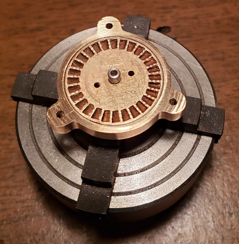
Participant@turbineguyMy new collet set arrived, so I finished more machining of the Drag Turbine 3 Housing. The housing was designed so that all the critical machining could be done without removing the casting from the 4 jaw chuck. This keeps all the bores as concentric and the faces as perpendicular to the centerline of the housing as possible. After I reamed the bore for the ball bearings, I inserted one of the ball bearings and checked the fit. It was a very tight locational fit that required a light push to insert or remove the ball bearing. After all the other machining of the faces and bores, I placed the rotor in the housing to see what the clearance of the outer face of the rotor was to the outer face of the housing. With the inner face of the rotor against the inner face of the housing, the clearance was less than 0.003” (0.08mm). A 0.003” feeler gage would not slide into the gap but a 0.002” feeler gage would slide in. This is very close to the 0.002” (0.05mm) total clearance I was hoping to get. While the housing is still in the 4 jaw chuck, I added shims between the ball bearings extended inner race and face of the rotor hub. I then pushed the assembly into the housing. With five 0.001” (0.025mm) shims, the inside face of the rotor cleared the inside face of the housing and the rotor would spin a few times when flicked with a finger. When I measured the clearance of the outer face of the rotor to the outer face of the housing, a 0.002” feeler gage could not be inserted. The following picture shows the rotor in the housing when the last measurements were made. I am very pleased with the results of the machining of the critical surfaces. It is a testament to the quality of the Unimat 3 and the EMCO accessories.
7 March 2021 at 12:09 #532325Turbine Guy
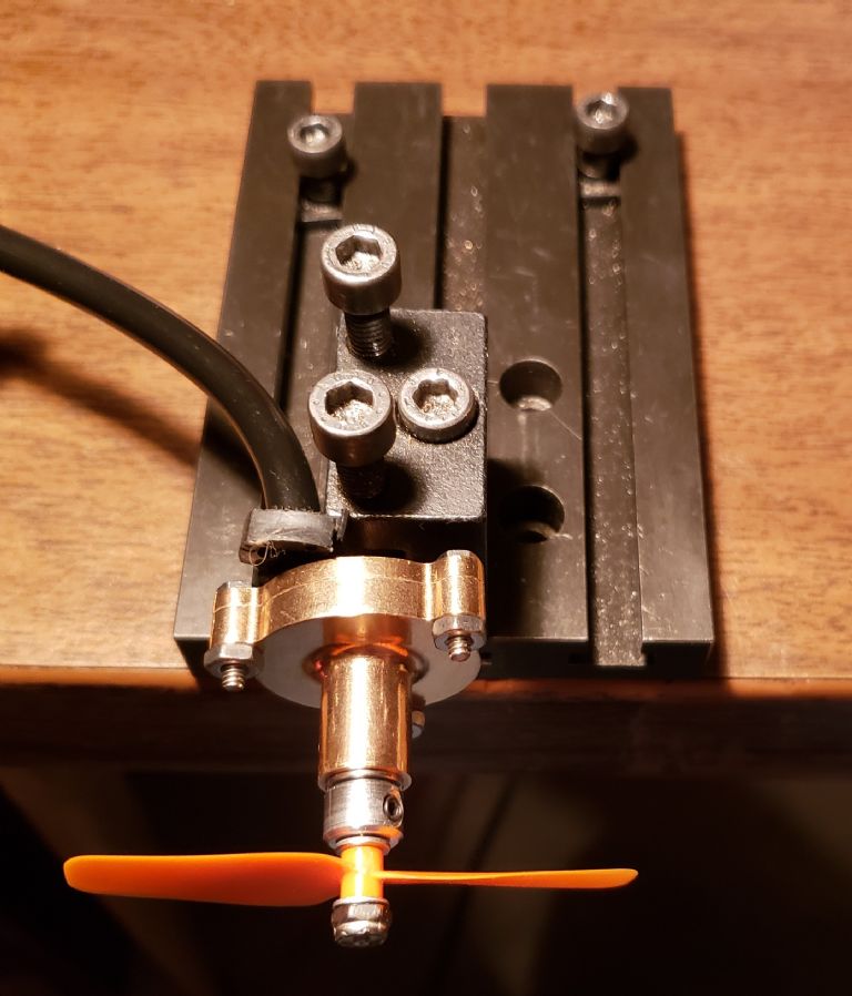
Participant@turbineguyI reamed the ball bearing bore in the Drag Turbine 3 housing using a drill chuck like I did on my other turbines before I decided to order the collet set. When I machined the cover plate and mounted it on the housing with the rotor and both ball bearings, there was some binding when I tried turning the shaft. After receiving the collet set, I found a way to true up the faces of the housing to make them more perpendicular to the axis of the ball bearing bore. This allowed the rotor to spin freely with the cover bolted tight to the housing. I added shims until I got the rotor as close to the cover as I could without any binding. When I tried running the turbine on air, the rotor didn’t spin. This indicated that the air pressure was tilting the rotor enough to contact on one or both faces. When I removed a single 0.001” thick shim, the rotor was free to spin under pressure, but the tilting opened up the clearances and reduced the pressure to about 5 psig. When I pushed on the end of the rotor shaft with the air brush compressor running, the pressure raised to about the 10 psig. 10 psig was the estimated pressure using O.E. Balje’s guidelines for Drag Turbine 3. The small diameter of the rotor shaft and the relatively long spacing between the ball bearings is probably what is allowing the rotor to tilt under pressure. Putting ball bearings on both sides of the rotor would probably be the best way to eliminate the tilting if the flow channel is on one side only. Putting the flow channel on both sides of the rotor would also help but would eliminate many of the advantages of the single side flow channel. With the pressure being only half of the design pressure, the maximum speed of the GWS EP 2.5×0.8 propeller was 18,500 rpm. The power required by this propeller at this speed is approximately 1.2 watts. There appears to be a lot of room for improvement of Drag Turbine 3, so don’t give up on the concept yet. The following picture is the Drag Turbine 3 setup for the first test. I want to wait until after all the changes to the housing and cover plate before I design a support bracket.
9 March 2021 at 12:50 #532766Turbine Guy
Participant@turbineguyI checked the total clearance between the rotor, housing, and cover plate. I removed the shim washers and bearings from the rotor and placed shim strips between the inner face of the rotor and the housing. I then bolted the cover plate tight to the housing. With 0.003” thick shim strips the rotor could be turned but with 0.004” thick shim strips the rotor was clamped tight. The total clearance is less than 0.004” for both sides of the rotor. I then started adding shim washers to the rotor, added the ball bearings, inserted the rotor into the housing, and bolted the cover plate tight to the housing. It took a total thickness of shim washers of 0.005” between the ball bearing extended inner race and the rotor hub to get enough clearance for the rotor to spin freely. I connected the hose from my airbrush compressor to the cover plate and ran a test with the GWS EP 2.5×0.8 propeller. The maximum speed reached was 9,500 rpm. I then found the maximum rpm for each total shim washer thickness until I reached the thickness that caused the rotor to contact the cover plate. The maximum rotor speed for 0.005”,0.006”, and 0.007” total shim washer thickness was 9,500 rpm, 14,500 rpm, and 17,500 rpm, respectively. I couldn’t reach the 18,500 rpm I was able to obtain in the first test of Drag Turbine 3. These tests show that the distance from cover plate to the rotor or the rotor to the inner housing surface can vary from 0.001” to 0.003” with a total clearance of 0.004”. It appears that the tilting of the rotor is less than 0.001” and that the distance from the rotor to the cover plate is most important. The air pressure increased from about 2 psig to 5 psig with each movement of the rotor toward the cover plate. The pressure readings are very hard to make with these very low pressures.
Edited By Turbine Guy on 09/03/2021 13:00:58
12 March 2021 at 12:32 #533399Turbine Guy
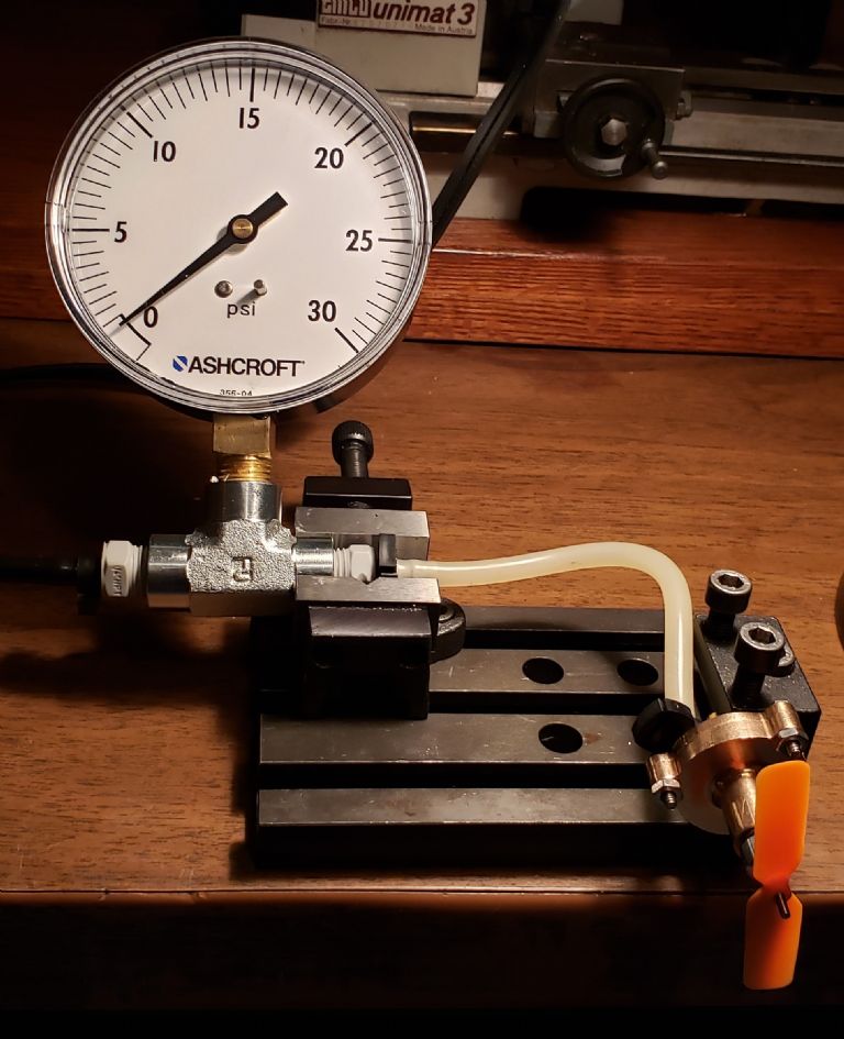
Participant@turbineguyI bought a 0-30 psig pressure gauge with increments of 0.5 psi in order to get more accurate readings at the very low pressures. The following picture shows my test setup with the new pressure gauge. The large 3.5” diameter dial and +/- 0.3 psi accuracy will really help. I made the following four pressure measurements. First, I measured the pressure with the cover plate removed and pressed tight against a flat surface. The pressure was approximately 2.5 psig. That is the pressure required to push all the flow through the existing channel size with smooth walls on all sides. The second measurement was with the cover plate bolted tight to the turbine housing with the rotor supported by the ball bearing but pushed tight against the cover plate. The pressure was approximately 9.5 psig. That is the pressure required to push all the flow through the existing channel size with blades and without leakage. The 7 psig increase in pressure was due to the resistance to flow that the blades cause. The third measurement was with the 0.007” total thickness of shim washers keeping the face of the rotor as close to the face of the cover plate as I was able to do without any contact. The pressure was approximately 5.0 to 6.5 psig dependent on the rotor position. That is the pressure required to push all the flow through the existing channel size with blades and with leakage. The flow channel area was sized per Dr. Balje’s guidelines to require 10 psig air pressure with very small leakage. The forth pressure measurement was with everything the same as the third measurement except with the turbine running at a speed of 18,500 rpm. I was able to reach that speed again with the GWS EP 2.5×0.8 propeller. The pressure was approximately 4.0 psig. Dr. Balje’s testing indicated the pressure should stay almost constant for speeds from stalled to design speed for his type of drag turbine. My tests showed approximately a 2.0 psi drop in pressure from average stall pressure. The leakage is the most significant problem needing to be resolved and the drop in pressure with rising speed is the second concern.
21 March 2021 at 11:18 #535185Turbine Guy
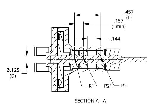
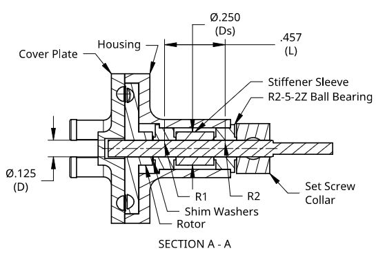
Participant@turbineguyThe following drawing is a section view of Drag Turbine 3 showing the dimensions needed for evaluating deflection. The diameter of the shaft (D) and the spacing between bearings (L) are two things that can be changed on this turbine without changing the cover plate or housing. The deflections change in direct proportion to the change of the moment of inertia (I) and for shafts I = πD^4/64. Three ball bearings of the type used in Drag Turbine 3 are available that will fit in the existing bearing bore and have the following nominal shaft sizes 1/8”, 5/32”, and 3/16”. Since the moment of inertia varies with the fourth power of shaft diameter, changing from the 1/8” shaft to a 5/32” shaft would increase the moment of inertia by a factor of 2.44. Likewise, changing from the 1/8” shaft to a 3/16” shaft would increase the moment of inertia by a factor of 5.06. Changing the shaft size will require modifying the existing rotor but could find what shaft size works best for this turbine. The downside of increasing the shaft size is the torque required to turn the ball bearings goes up with increased shaft sizes. The spacing between the bearings (L) could be changed by inserting a ball bearing without the flange in between the two existing ball bearings. The reduction in deflection is directly proportional to L, so placing the added ball bearing right next to the ball bearing closest to the rotor could reduce the deflection considerably. The downside to shortening the distance between bearing centers is that the load on the bearings increases in direct proportion to the reduction in center spacing. Having the extra ball bearing may result in the stiffest arrangement being with the center bearing moved more to the center.
21 March 2021 at 13:35 #535210 Michael GilliganParticipant@michaelgilligan61133
This is a brilliant write-up of your progress
Please don’t think you have no appreciative readers
… I’m just lost for any useful comment to make

MichaelG.
21 March 2021 at 17:58 #535294Turbine Guy
Participant@turbineguyMichael,
Thank you for your very kind remarks. We all like encouragement, and comments like yours give us the incentive to try new things.
Byron
22 March 2021 at 20:30 #535461DrDave
Participant@drdaveByron,
If you removed bearing R2' and increased the shaft diameter between the remaining two bearings, that would give you a small increase in stiffness. The biggest increase in stiffness would come from adding a bearing in the left hand housing, on the opposite side of the turbine from the existing bearings: is there a reason that you cannot do that?
And keep up the good work. It is fascinating watching your development process.
Dave
22 March 2021 at 21:48 #535467Turbine Guy
Participant@turbineguyHi Dave,
I looked at what you suggested. The following drawing shows the way I think you intended to move the bearing. This would be the best solution but would require a new cover plate, since a ball bearing won't fit in the existing cover plate. I ordered the flangeless ball bearing and it is supposed to arrive tomorrow. I'm going to try using it between the existing bearings first since it doesn't require a change to any of the existing parts.
Thanks for the feedback,
23 March 2021 at 14:35 #535583Turbine Guy
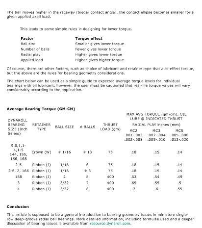
Participant@turbineguyI looked at the friction torque of the three ball bearings that will fit in my existing Drag Turbine 3 housing. Dynaroll is the supplier of the ball bearings and gave the guidelines shown below for the resistance torque. The 1/8” shaft size ball bearing has a total of 6, 1/16” diameter balls. The 5/32” and 3/16” shaft sizes ball bearings have a total of 10, 0.039” diameter balls. The load on the ball bearing closest to the rotor is the largest and is primarily axial with bending moment. The smallest shaft size has fewer but larger diameter balls so the reduction in torque for a smaller number of balls is offset by the larger ball size. Likewise, the larger shaft sizes have more but smaller diameter balls so the reduction in torque for smaller diameter balls is offset by the larger quantity. The pitch diameter of the balls in the bearing with the 1/8” diameter shaft is 0.227” and for the bearings with the larger shafts is 0.253” so that is not much of a factor. It appears that the resistance torque of the ball bearings will be about the same regardless of shaft size. The resistance torque of ball bearings is normally considered insignificant, but I found in the testing of my other turbines it can affect performance. I was able to gain an additional 0.8 watt of power just by balancing the rotor as discussed in the post of 30/05/2020 Link. The following was copied from that post.
"When I first put a shaft in the cast rotor Werner Jeggli gave me, I was anxious to test it and ran the test before balancing the rotor. The maximum speed running on air for the unbalanced rotor was 18,000 rpm. The maximum speed running on air for the balanced rotor was 21,500 rpm. This is an increase in power of approximately 0.8 watts due to balancing".
Edited By Turbine Guy on 23/03/2021 14:42:58
24 March 2021 at 14:36 #535806Turbine Guy
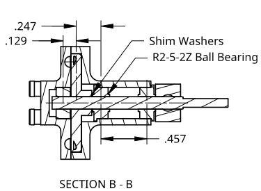
Participant@turbineguyI tried running Drag Turbine 3 with the flangeless ball bearing between the existing ball bearings as shown in the following drawing and using a GWS EP 2.5×0.8 propeller. With a total shim thickness of 0.007” the maximum speed was 14,000 rpm and the pressure was 4.0 psig. With the third ball bearing added, there was slight contact of the rotor with the cover plate with the 0.007” total shim thickness. With a total shim thickness of 0.006” there was no contact of the rotor with the cover plate or housing and the maximum speed was 13,500 rpm and the pressure was 3 psig. The performance was about the same for the 0.007” and 0.006” total shim thicknesses. Moving the rotor 0.001” further away from the cover plate eliminated the contact but dropped the pressure 1 psig. When I removed the third bearing, the maximum speed with 0.006” total shim thickness was 15,000 rpm and the pressure was 3.3 psig. With a total shim thickness of 0.007” the speed was 18,500 rpm and the pressure was 4.0 psig. Adding the third bearing reduced the performance. Apparently any improvement for reducing deflection was more than offset with the extra friction caused by the increased bearing load.
27 March 2021 at 16:28 #536551Turbine Guy
Participant@turbineguyI tried adding a sleeve between the ball bearings as shown in the following drawing. The sleeve was reamed to a very close sliding fit with the rotor shaft. Even the slightest bending of the rotor shaft would cause contact with the sleeve. The sleeve diameter of ¼” is twice the diameter of the rotor shaft so the effective moment of inertia of the rotor and sleeve increases by a factor of 16. I thought that this would stop the shaft from deflecting without increasing the bearing loads. The ball bearings were starting to make noise indicating they needed lubrication, so I added a drop of Krytox GPL102 oil to each ball bearing. This oil has a higher viscosity than the Aeroshell 12 oil that comes with the ball bearings but is the best replacement I have found. The maximum speed with a total shim washer thickness of 0.007” and a GWS EP 2.5×0.8 propeller was 15,500 rpm with or without the sleeve. The extra stiffness added by the sleeve appeared to make no difference. This was a much larger drop in speed from the 18,500 rpm that I was able to reach before I heard the bearing noise than oil viscosity would cause. I don’t know if the axial load the ball bearings get with the flow channel on only one side has shortened the life and the ball bearings are worn out, but the noise is gone.
I made a mistake in the machining of the rotor for Drag Turbine 3 that was explained in the 17/01/2021 post on page 13. The loss of most of the rotor boss compromised its strength and I need to make a new rotor rather than try fixing the existing one. I ordered the casting for a rotor like mentioned in the 23/02/2021 post on page 13. Maybe with the rotor machined correctly, Drag Turbine 3 will perform like it should.
9 April 2021 at 19:54 #538907Turbine Guy
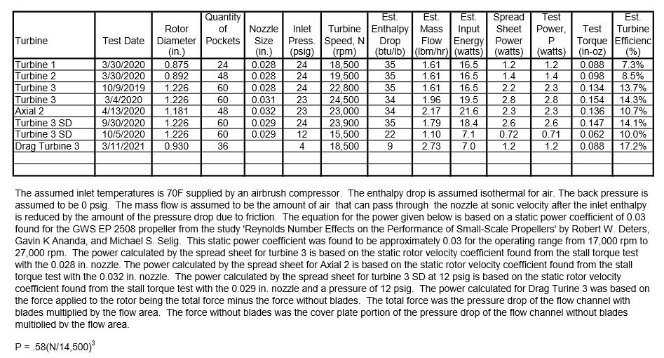
Participant@turbineguyI updated the following table to include the performance of Drag Turbine 3 running on air. It is interesting that it had one of the lowest power outputs but was the highest in efficiency. The higher efficiency of the drag turbine compared with the impulse turbines at very low pressures and speeds is what attracted me to this concept. I still believe it can outperform my impulse turbines running on my airbrush compressor, if I can reduce the leakage. My airbrush compressor can't supply enough air to get the pressure up to the design pressure of 10 psig with the existing leakage. My new cast rotor is scheduled to arrive late today. I’ll see if what I believe to be design improvements and hopefully better machining will get me closer to my goal with Drag Turbine 4.
10 April 2021 at 03:27 #538947 Blue HeelerParticipant@blueheeler
Very interesting thread to read through, this is a DIY Steam Turbine that i built recently and its first test on steam –
-
AuthorPosts
- Please log in to reply to this topic. Registering is free and easy using the links on the menu at the top of this page.
Latest Replies
Home › Forums › Stationary engines › Topics
-
- Topic
- Voices
- Posts
- Last Post
-
-
Some help with a Cowells speed controller needed.
Started by:
Hollowpoint in: Electronics in the Workshop
- 3
- 8
-
28 April 2025 at 09:45
Hollowpoint
-
minimag set up
Started by:
Dalboy in: General Questions
- 4
- 4
-
28 April 2025 at 09:42
 JasonB
-
Lantern Pinion
1
2
Started by:
Alan Charleston in: General Questions
- 10
- 26
-
28 April 2025 at 09:40
bernard towers
-
Bending EN24t
Started by:
vintagengineer in: Workshop Techniques
- 10
- 19
-
28 April 2025 at 09:16
Keith Bloor
-
Anyone know about wells and Victorian plumbing?
Started by:
Ian Parkin in: The Tea Room
- 14
- 19
-
28 April 2025 at 08:36
Andrew Crow
-
Emco FB2 and Maximat Mill?
Started by:
beeza650 in: Beginners questions
- 4
- 6
-
28 April 2025 at 07:00
 JasonB
-
Museum of Science and Technology of Catalonia
Started by:
 Sonic Escape
in: The Tea Room
- 2
- 2
-
28 April 2025 at 06:51
 Michael Gilligan
-
Fitting DRO to Myford VME mill.
Started by:
Martyn Cozens in: Manual machine tools
- 5
- 5
-
27 April 2025 at 23:59
Nigel Graham 2
-
Geography lesson required? Crossley Engine
Started by:
duncan webster 1 in: The Tea Room
- 11
- 16
-
27 April 2025 at 23:02
Nigel Graham 2
-
Boiler Examinations: 7-yearly External Query
Started by:
Nigel Graham 2 in: Traction engines
- 5
- 13
-
27 April 2025 at 22:45
Nigel Graham 2
-
Amazing Fellow and his musical machines..
Started by:
Joseph Noci 1 in: The Tea Room
- 2
- 2
-
27 April 2025 at 22:19
Plasma
-
Small horizontal mill – capabilities?
Started by:
ell81 in: Beginners questions
- 15
- 18
-
27 April 2025 at 21:50
Nigel Graham 2
-
Scam email
Started by:
Ian McVickers in: General Questions
- 11
- 12
-
27 April 2025 at 21:40
Nigel Graham 2
-
Armortek series 1 landrover kit
1
2
Started by:
Plasma in: Miscellaneous models
- 7
- 34
-
27 April 2025 at 20:44
noel shelley
-
24cc DIESEL ENGINE FROM SOLID
Started by:
 dean clarke 2
in: I/C Engines
- 10
- 25
-
27 April 2025 at 20:29
bricky
-
Building Bernard Tekippe’s Precision Regulator
1
2
3
Started by:
Chris Raynerd 2 in: Clocks and Scientific Instruments
- 11
- 52
-
27 April 2025 at 20:25
Chris Raynerd 2
-
Stuart Twin Victoria (Princess Royal) Mill Engine
1
2
…
49
50
Started by:
Dr_GMJN in: Work In Progress and completed items
- 32
- 1,234
-
27 April 2025 at 18:01
Dr_GMJN
-
mt4.5
Started by:
Matt Smith in: General Questions
- 3
- 3
-
27 April 2025 at 15:43
DC31k
-
French Curves
Started by:
 Michael Gilligan
in: CAD – Technical drawing & design
- 2
- 2
-
27 April 2025 at 13:02
 JasonB
-
Change Wheels
Started by:
Julian Goodyear in: Workshop Tools and Tooling
- 10
- 24
-
27 April 2025 at 12:22
halfnut
-
Power hacksaw – powerful banging when running
Started by:
ell81 in: Beginners questions
- 8
- 11
-
27 April 2025 at 08:21
John Haine
-
How To Make A Pressure Gauge Syphon?
Started by:
 MEinThailand
in: CAD – Technical drawing & design
- 4
- 7
-
27 April 2025 at 07:10
 JasonB
-
Drummond round bed
Started by:
old mart in: Manual machine tools
- 3
- 4
-
27 April 2025 at 07:10
 David George 1
-
Dodgy car parts a new low
Started by:
jon hill 3 in: The Tea Room
- 11
- 13
-
26 April 2025 at 22:57
 Robert Atkinson 2
-
Metric Thread Cutting Without Conversion Wheel
Started by:
Nigel Graham 2 in: Hints And Tips for model engineers
- 7
- 10
-
26 April 2025 at 21:04
Nigel Graham 2
-
Some help with a Cowells speed controller needed.
-
Latest Issue
Newsletter Sign-up
Latest Replies
- Some help with a Cowells speed controller needed.
- minimag set up
- Lantern Pinion
- Bending EN24t
- Anyone know about wells and Victorian plumbing?
- Emco FB2 and Maximat Mill?
- Museum of Science and Technology of Catalonia
- Fitting DRO to Myford VME mill.
- Geography lesson required? Crossley Engine
- Boiler Examinations: 7-yearly External Query


