Model Turbines

Advert

Model Turbines

Home Forums Stationary engines Model Turbines

Viewing 25 posts - 226 through 250 (of 562 total)
  • Author
    Posts
  • #512726
    Turbine Guy
    Participant
      @turbineguy

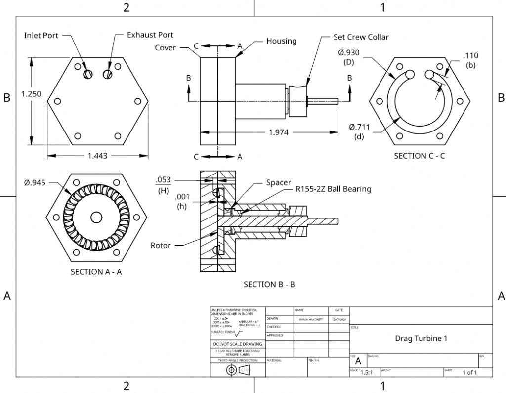
      To obtain the efficiency shown in the last post, my Drag Turbine 1 must meet certain requirements. I will list some of these requirements below and some in the next post. The requirements that apply to the cover and housing shown in the following drawing are:

      The channel diameter/width ratio, D/H needs to be approximately 17.5. The channel diameters ratio, D/d, needs to be between 1.3 to 1.5 The rotor clearance to channel width ratio, h/H, needs to be less than 0.02

      Drag Turbine 1

      Edited By Turbine Guy on 10/12/2020 20:51:15

      Edited By Turbine Guy on 10/12/2020 20:52:05

      Advert
      #512736
      Turbine Guy
      Participant
        @turbineguy

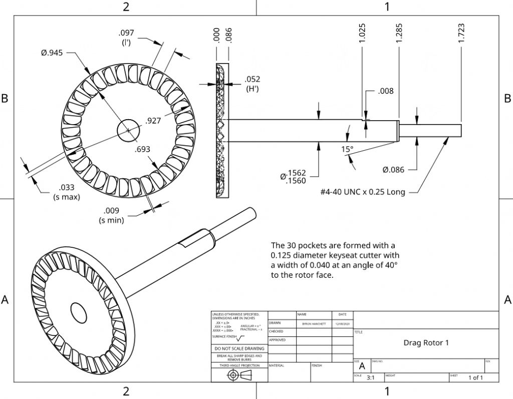
        The requirements of the rotor shown in the following drawing to obtain the efficiency shown in the post of 09/12/2020 are:

        The rotor pocket depth to cover channel depth ratio, H’/H, should be approximately 1. The angle of the rotor pockets should be 40 degrees. The blade thickness to cover channel depth ratio, s/H should be less than 0.20. The pocket spacing to cover channel depth ratio, l’/H, should be between 1 and 2.

        Drag Rotor 1

        #513099
        Turbine Guy
        Participant
          @turbineguy

          In the last posts I gave the drawings showing the dimensions for Drag Turbine 1. I also gave the requirements that had to be met to achieve an estimated efficiency of 30%. The following is a copy of the requirements and at the end of each requirement the corresponding values of Drag Turbine 1 are shown in parentheses.
          The channel diameter/width ratio, D/H needs to be approximately 17.5 (17.5). The channel diameters ratio, D/d, needs to be between 1.3 to 1.5 (1.3). The rotor clearance to channel width ratio, h/H, needs to be less than 0.02 (0.02). The rotor pocket depth to cover channel depth ratio, H’/H, should be approximately 1 (1.0). The angle of the rotor pockets should be 40 degrees (40 degrees). The blade thickness to cover channel depth ratio, s/H should be less than 0.20 (0.17 min 0.62 max) The pocket spacing to cover channel depth ratio, l’/H, should be between 1 and 2 (1.8). In addition to these requirements the ratio of the inlet gas density to the outlet gas density needs to be less than 2. For air at an inlet pressure of 10 psig and exhausting to atmosphere pressure, the ratio is approximately 1.7. Drag Turbine 1 meets all the requirements except for the blade thickness. Dr. Balje’s report assumes a constant blade thickness and has a chart showing the loss of efficiency with s/H ratios greater than 0.2. Since Drag Turbine 1 has varying blade thickness, I make a few assumptions to use the chart. Because the flow enters the bottom of the pockets and flows out the top of the pockets, I assume that the blade thickness on the lower half should be used. The average blade thickness on the lower half is approximately 0.015”. This makes the s/H ratio for the lower half 0.015/0.053 = 0.28. For a s/H ratio of 0.28, Dr. Balje’s chart gives an efficiency correction of 0.95. With this correction, the estimated efficiency of Drag Turbine 1 is approximately 28%.

          #513167
          Turbine Guy
          Participant
            @turbineguy

            The estimated efficiency for Drag Turbine 1 is based on what my airbrush compressor is capable of. When I determined that I needed the air pressure to be 10 psig, I ran tests with a nozzle to see what throat size took all the flow at 10 psig. I found that a nozzle bore of 0.047 diameter could pass all the flow my airbrush compressor was capable of at 10 psig. The mass flow for 10 psig inlet pressure, atmospheric exhaust, and a nozzle efficiency of 95% is estimated to be 3.0 lb/hr. The enthalpy drop for these pressures, assuming isothermal flow, is approximately 19 btu/lb. For this mass flow and enthalpy drop the input energy of the air is approximately 16.6 watts. With the estimated efficiency of 28% given in the last post, the estimated power at 25,000 rpm is 4.6 watts. The maximum power of any of my turbines or steam engines running on my airbrush compressor was the 4.7 watts my Chiltern steam engine was able to produce Testing Models. The Chiltern is a very nice engine with a fully supported crankshaft, piston valve, and Teflon piston rings. If Drag Turbine 1 can be built and is able to reach the estimated efficiency, it would be pretty impressive performance for a small turbine running at only 25,000 rpm. Probably the biggest advantage of the drag turbine over the impulse turbines running on very low input energies, is the effect of Reynolds number. The Reynolds number tends to drop dramatically with very low input energies. This causes a corresponding loss in efficiency for impulse turbines but has almost no effect on drag turbines. The drag turbines were given their name since they relied on increasing the drag force on the rotor to much higher levels than the drag force on the flow channel. Even though the increased drag on the rotor is caused by the dynamic effects of the spiral flow, it is treated like a viscous drag in the analysis.

            #514223
            Turbine Guy
            Participant
              @turbineguy

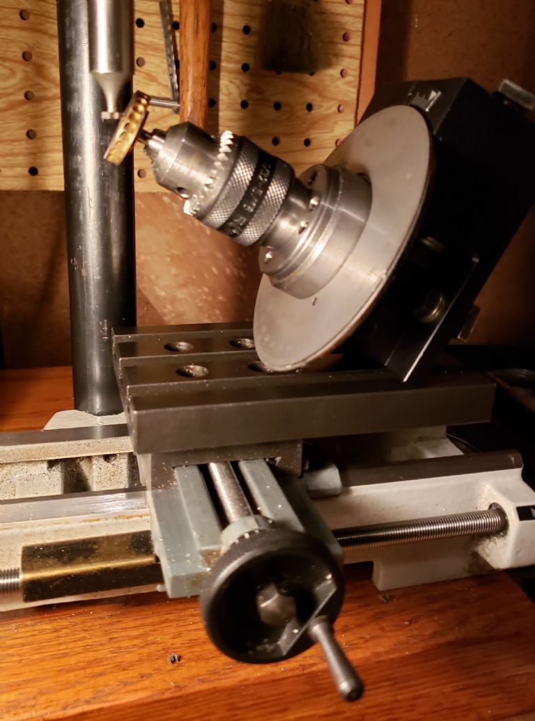
              The following photo is a mockup of the best setup I have been able to come up with to make the pockets in the rotor of Drag Turbine 1. The rotor used in the mockup is approximately the size of the drag rotor. The keyway mill is the only one I have and is much bigger than the size needed. Also, the indexer is just set at the approximate angle. I used this mockup to determine If I had room to get everything in position. A 45 degree angle bracket shown in the next post is available and could be used for mounting the indexer to the carriage mounting plate. This bracket could be used instead of the 40 degree optimum angle with just a slight loss in drag coefficient.

              Drag Rotor Setup 1

              #514226
              Turbine Guy
              Participant
                @turbineguy

                The following is a copy of the bracket I mentioned in the last post. This has a hole spacing that I think will fit in the space available. I placed an order for this set of brackets since I want to make sure they will work before purchasing the expensive keyway cutter needed to make the pockets in the drag rotor. Angle Bracket

                #514232
                Werner Jeggli
                Participant
                  @wernerjeggli14222

                  Byron,

                  Your having a go at a drag turbine is very commendable and I wish you success. But instead of machining the rotor it would be much simpler to have it lost wax cast by shapeways. It really does not cost that much!

                  #514243
                  Turbine Guy
                  Participant
                    @turbineguy
                    Posted by Werner Jeggli on 18/12/2020 20:01:56:

                    Byron,

                    Your having a go at a drag turbine is very commendable and I wish you success. But instead of machining the rotor it would be much simpler to have it lost wax cast by shapeways. It really does not cost that much!

                    Hi Werner,

                    You make a good point. The pockets in the drag rotor are much easier to cast than the blades in your rotors and are more accessible for cleanup, so this probably would be good to try. By casting the rotor, the thickness at the entrance to the pockets could be made the same all the way across and that would help the flow. I'll take a look at designing for casting both the rotor and housing. Thanks for the idea.

                    Hope your projects are going well,

                    Byron

                    #514983
                    Turbine Guy
                    Participant
                      @turbineguy

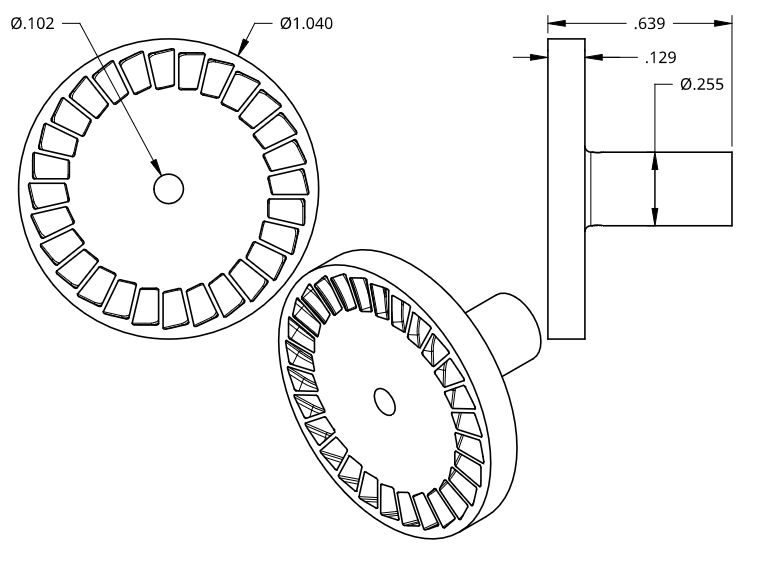
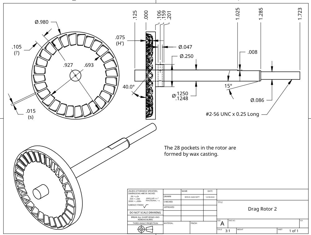
                      I designed a wax cast rotor that would work in place of the machined rotor in Drag Turbine 1. I added a couple of what I think are improvements. I added a boss on the rotor to replace the spacer in Drag Turbine 1. This extends the grip on the shaft and would allow a pin to be inserted through the rotor and rotor shaft. I also extended the shaft so that it passes through the rotor. This would allow balancing the rotor using Werner’s method described in the post of 29/11/2020. I made a 3D model of the rotor adding an allowance for machining the critical surfaces to their final dimension. I then scaled up the solid model 2% to allow for shrinkage. The following drawing of the solid model was made to show enough dimensions to confirm the scale. I went to the Shapeways Website and followed their instructions for getting a quote. The instructions were very straightforward except they always call it 3D printing even if you select materials like the bronze I requested, that is only available with wax casting. To get a quote you need a 3D solid part file. I made a step file for my drag rotor and dragged and dropped it where they requested. Their program responded that the file was very complex and would take a little time to analyze. After a short time, their program showed a 3D model that looked correct, but their assumed scale was wrong. I used the dimensions in the following drawing to correct the scale. The only thing left to do was select the material. After selecting the material, the price, expected ship date, and shipping cost were shown. My rotor cost $63.46 including shipping and has an estimated ship date of 13/01/2021. I thought the cost was reasonable for a quantity of 1, so I placed an order. The keyway cutter I required for making the machined rotor cost $52. Werner was right, this is a better way to go.

                      Drag Rotor Casting

                      Edited By Turbine Guy on 22/12/2020 19:49:25

                      #515278
                      Turbine Guy
                      Participant
                        @turbineguy

                        The following drawing shows the dimensions of the cast drag rotor after machining. This drawing assumes the casting will clean up to these dimensions. These dimensions assume the minimum amount I think will have to be taken off. There is quite a bit of additional allowance for cleanup if needed. The changes from Drag Rotor 1 are reducing the shaft diameter from 5/32” to 1/8” and adding a boss to extend the contact surface of the cast rotor to the shaft. The extra contact length also provides enough room to add a pin through the rotor and shaft. The change in shaft diameter was made since the ball bearings for the smaller diameter had higher load capacity and a higher allowable speed. Also, shims were available in 0.001” thickness where 0.004” was the minimum thickness for the larger shaft. The drag turbine requires the minimum clearance of the rotor and housing to get the best performance and the 0.001” shims will be very helpful in lining up the rotor with small clearances. The cast rotor allowed the pockets to have a full radius on each side, whereas the shank of the keyway cutter limited the depth of cut. Also, the blades of the casting have the same thickness from the bottom to the top of the pocket.

                        Drag Rotor 2

                        Edited By Turbine Guy on 24/12/2020 15:10:22

                        #515309
                        Turbine Guy
                        Participant
                          @turbineguy

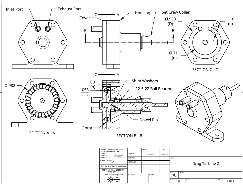
                          The following drawing is the assembly with the cast rotor, cast housing, and cast cover. After seeing the cost of the cast rotor, I thought I would look at using castings for the cover and housing. If Shapeways can cast them and the cost is reasonable, I will probably place an order. The castings save a lot of machining and simplify adding fillets and rounding surfaces which reduces the mass and improves the appearance.

                          Merry Christmas,

                          Byron

                          Drag Turbine 2

                          #516307
                          Turbine Guy
                          Participant
                            @turbineguy

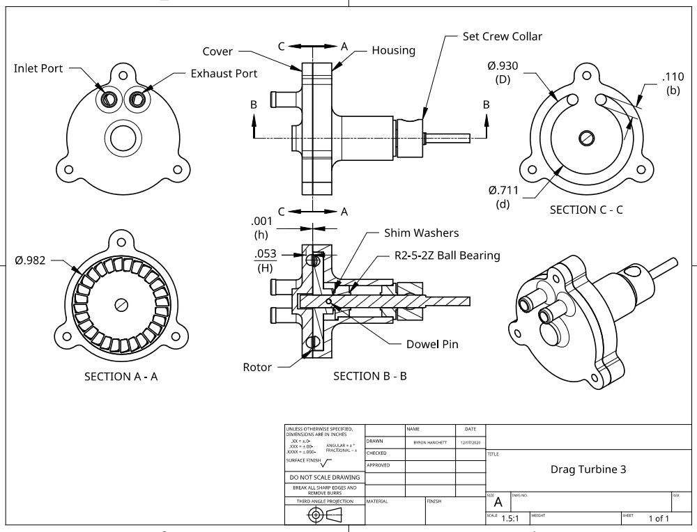
                            I requested a quote for casting the housing and cover plate shown in the last post. The cost was higher than I thought it would be, so I asked Shapeways for some guidelines to reduce the cost. This is the link to the guidelines they sent me Shapeway Guidelines. They also said bronze models are first printed in wax and then cast in bronze. After reading their guidelines, I found that I needed to reduce the volume and overall length of the castings as much as possible. I got quotes on a few changes to the hexagonal shape and then tried reducing the volume even further by changing the shape to what is shown in the following drawing. My goal was to get the cost for casting the rotor, housing, and cover plate down to around $200. The castings for the parts shown in the following drawing cost a total of $229 including taxes and shipping. This was close enough to my goal, so I placed an order for the housing and cover plate that are expected to be shipped 21/01/2020.

                            Drag Turbine 3

                            #517299
                            Turbine Guy
                            Participant
                              @turbineguy

                              While working on the cast housing and cover plate, I asked Shapeways what the minimum allowable thickness was and was given this link Shapeways Materials. Since I had already looked at the materials, I took a closer look and found there was a separate tab called ‘Design Guidelines’. This section gave the minimum thickness as 0.6mm for supported or unsupported sections with a natural finish. Since the minimum thickness of the blades of Drag Rotor 2 is approximately .01” (.3mm), I was concerned that the rotor would not be able to be cast as designed even though it passed the initial review by Shapeways. I mentioned what I had discovered to Shapeways and Mitchell Jetten of Shapeways Customer Service sent me the following response.

                              “The minimum acceptable wallthickness for this material is 0.6mm. For details, parts that stick out, you should be able to go down to as low as 0.35mm thick and 0.35mm long. If the detail sticks out more than 0.35mm this will be classified as wall instead and would require to be 0.6mm thick.
                              The main reason we have this guidelines is because we need to actually be able to 3D print the wax model, clean this and create a negative mold around this before we are able to cast the model in brass. Since the wax material is really fragile, going below this guideline greatly increases the risk of parts breaking or warping.
                              On our materials page by clicking on the Design Guidelines tab you can read more about this:

                              That said, our checking process is manual, it does happen from time to time that a model that is below the design guidelines gets approved. In your case the model was successfully printed and cast, however it often also happens that a model gets accidentally accepted and then gets printed or cast but fails at either of these stages, which will result in the model being rejected".

                              After receiving this response I was notified by Shapeways that Drag Rotor 2 was cast and cleaned up successfully and has been shipped. I thought I would share Mitchell's explanation of the importance of the minimum thickness, The reason the blades of Drag Rotor 2 were able to be cast was probably because their unsupported length is so short.

                              Edited By Turbine Guy on 03/01/2021 20:11:36

                              #517308
                              DrDave
                              Participant
                                @drdave

                                That is really useful feedback on Shapeways. Their customer support & turn-around time are impressive, especially over the feastive season. I am intending to try their 3d printing in aluminium shortly, based on the input from Werner & yourself.

                                Dave

                                #517312
                                Roger Best
                                Participant
                                  @rogerbest89007

                                  cool Its amazing they work but I just love it.

                                  The 3D Printing is wonderful too.

                                  Keep up the good work Turbine Guy.

                                  #517319
                                  Turbine Guy
                                  Participant
                                    @turbineguy

                                    Thanks for the responses Dave and Roger. I see a lot of possibilities for having parts made by Shapeways. It's interesting the different ways they can make the parts, like binder jetting, wax casting, and selective laser melting. Also the different materials they have available for the parts. I am also very pleased with the way they respond to questions and how quick they can make a quote.

                                    Happy New Year

                                    Byron

                                    #517879
                                    Turbine Guy
                                    Participant
                                      @turbineguy

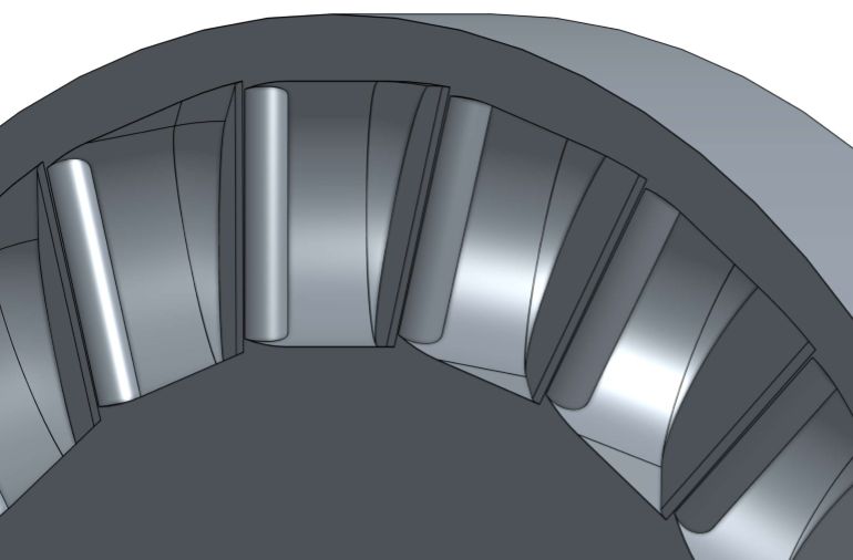
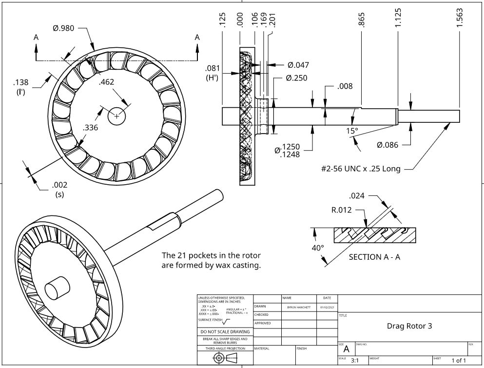
                                      I designed Drag Rotor 3 following all the guidelines from Shapeways. The two guidelines I missed on Drag Rotor 2 were keeping the minimum thickness greater than 0.6mm minimum for bronze and having a sharp edge on a thin section. The blades on Drag Rotor 3 are 0.6mm thick and have a round end. The following picture shows a 3D view of the blades. The drawing for this rotor will be shown in the next post. I should point out that Shapeways minimum thickness is not the same for all materials so should be checked. I may try this rotor if I have a problem with Drag Rotor 2 since it will work with the cast housing and cast cover plate of Drag Turbine 3.Drag Rotor 3 Blades

                                      #517880
                                      Turbine Guy
                                      Participant
                                        @turbineguy

                                        This is the drawing for Drag Rotor 3. I had to make the pockets deeper and reduce the number of blades to open up the flow area with the extra blade thickness.  

                                        Drag Rotor 3

                                        Edited By Turbine Guy on 06/01/2021 14:01:08

                                        #517909
                                        Werner Jeggli
                                        Participant
                                          @wernerjeggli14222

                                          Am I correct in assuming that the use of the Spencer one sided blower principle to a turbine rotor would result in a bidirectional turbine while your adaptation is uni-directional. Would be a big disadvantage for model applications!

                                          Werner

                                          #517935
                                          Turbine Guy
                                          Participant
                                            @turbineguy

                                            Hi Werner,

                                            If the Spencer blowers use 90 degree blades they would be truly bidirectional. You are right that using the 40 degree blades makes the turbine almost unidirectional. My design would have some torque running in the opposite directions if the flow in the ports is reversed. You bring up a very interesting point about running in both directions, I have not looked at that. Using the 90 degree blades would make the drag turbine truly reversible but quite a bit less efficient. The maximum efficiencies found for the tests of 90 degree blades and 40 degree blades in 'A STUDY OF HIGH ENERGY LEVEL, LOW POWER OUTPUT TURBINES' by Dr. Balje are 20% and 33% respectively. These were from actual tests so should give an indication of the difference in efficiency. We have both seen that things don't always work out the same for miniature steam models so there might not be this much difference. I may try a rotor with 90 degree blades and see how it does.

                                            Thanks for bringing this up,

                                            Byron

                                            Edited By Turbine Guy on 06/01/2021 15:30:55

                                            #518923
                                            Turbine Guy
                                            Participant
                                              @turbineguy

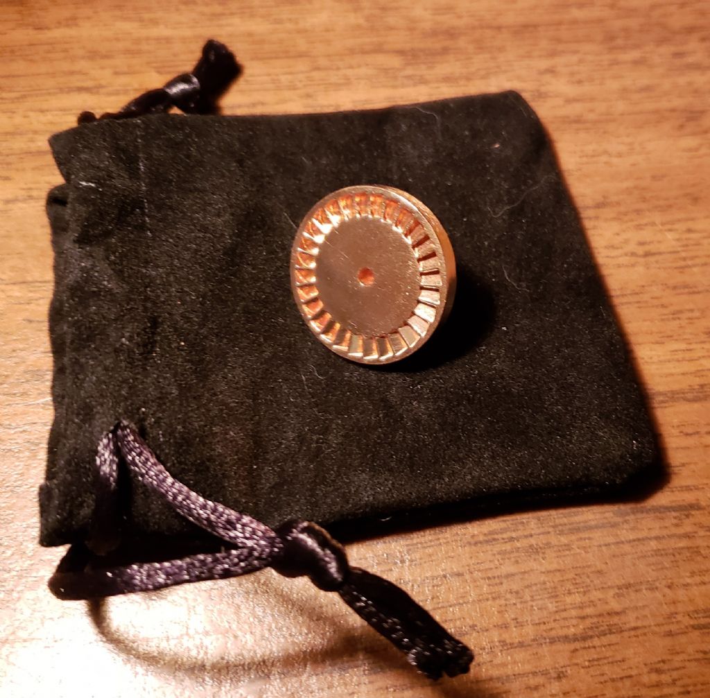
                                              My casting for Drag Rotor 2 arrived and looks very good. The following photo shows it sitting on the bag it was shipped in. Putting it in a jewelry bag was a nice touch. The measurement around the OD and across the face of the rotor varied by approximately +/- 0.002" (0.05mm). The actual OD after casting averaged approximately 1.026”. This OD on the 3D model used to make the casting, shown on the drawing in the post of 22/12/2020, is 1.04”. From Shapeways Bronze Guidelines the average shrinkage is given as 2.5%. For a after casting OD of 1.026” and a shrinkage of 2.5%, the mold ID would be approximately 1.05” before casting. This is approximately 0.01” larger than the 3D model, so the accuracy of the mold should also be considered. The machining allowance I assumed for Drag Rotor 2 was for the casting to be +/- 0.020" and is probably about right for this size of casting.

                                              Drag Rotor 2-1

                                              #518969
                                              Roger Best
                                              Participant
                                                @rogerbest89007
                                                Posted by Werner Jeggli on 06/01/2021 14:26:08:

                                                Am I correct in assuming that the use of the Spencer one sided blower principle to a turbine rotor would result in a bidirectional turbine while your adaptation is uni-directional. Would be a big disadvantage for model applications!

                                                Werner

                                                Hey Werner, what model needs a shaft speed of 25000rpm? Almost everything, other than a noise maker, will need a reduction gearbox and that means direction control is possible.

                                                The main problem all small models have is efficiency, so optimising for power is a good start. yes

                                                #519131
                                                Werner Jeggli
                                                Participant
                                                  @wernerjeggli14222

                                                  Hi Roger,

                                                  You are right of course, but then you will have problems with remote controlling the reversing gear because of unsynchronised tooth positions. In addition it will not be possible to dynamically brake the model with counter steam. I built such a gauge 1 turbine loco drive many years ago – that's why I know.

                                                  #519178
                                                  Turbine Guy
                                                  Participant
                                                    @turbineguy

                                                    Hi Roger and Werner,

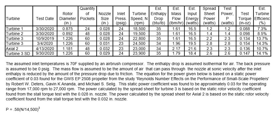
                                                    If the drag turbine works well enough to demonstrate the efficiency estimated by Dr. Balje can be approached with my tiny model, that would indicate that an efficiency in the range of 15% to 20% could be obtained with 90 degree blades. The best efficiency I have been able to obtain from my tangential and axial impulse turbines using my airbrush compressor and smallest propeller is approximately 14% as shown in the table below. If an efficiency of over 15% can be obtained with 90 degree blades, it would be higher than I have been able to obtain up to date and have full power in both directions. This would be quite a bit less than the 28% efficiency I hope to get with the 40 degree blades but would still be a major improvement and I think worth testing.

                                                    Thanks for the feedback,

                                                    Byron

                                                    Turbine Test Results 11

                                                    #519355
                                                    Turbine Guy
                                                    Participant
                                                      @turbineguy

                                                      In the post of 10/01/2021 I discussed how the shrinkage on the casting for Drag Rotor 2 did not seem to match Shapeways average of 2.5% for bonze. After discussing this with a Shapeways customer service representative, I found that the shrinkage is not an exact amount. It varies with the size and shape of the casting and can be different for some locations in the casting. For my size and type of casting he suggested 2% shrinkage would be a better estimate. This is about what the shrinkage was on the OD, the longest dimension of this casting. If the shrinkage is critical in your design it might be a good ideal to discuss this with a Shapeways customer service representative.

                                                    Viewing 25 posts - 226 through 250 (of 562 total)
                                                    • Please log in to reply to this topic. Registering is free and easy using the links on the menu at the top of this page.

                                                    Advert

                                                    Latest Replies

                                                    Home Forums Stationary engines Topics

                                                    Viewing 25 topics - 1 through 25 (of 25 total)
                                                    Viewing 25 topics - 1 through 25 (of 25 total)

                                                    View full reply list.

                                                    Advert