Mixing fractions and decimal units in an imperial drawing

Advert

Mixing fractions and decimal units in an imperial drawing

Home Forums CAD – Technical drawing & design Mixing fractions and decimal units in an imperial drawing

Viewing 15 posts - 51 through 65 (of 65 total)
  • Author
    Posts
  • #265277
    JasonB
    Moderator
      @jasonb

      Sarah, dependingon what drawing program you are using you may not need to do a reprint, as there is often an option to have a secondary form of dimensioning.

      This one is decimal imperial and fractions, note that it has a tendancy to round to teh nearest fraction hence the 3mm (0.118" ) dimension is rounded to 1/8" , the drawing is set to use the nearest 64th.

      This one has decimal imperial and metric, which is handy as although the engine is basically being built in imperial you can see I have used some metric thickness plate

      J

      Advert
      #265282
      Ian P
      Participant
        @ianp

        Jason

        Purely out of interest. Are these drawings just examples that you have dimensioned for illustration to Sarah?

        It look like the original source data was imperial fractional measurements, but why does 1/8" not convert to 0.125" ?

        Ian P

        #265288
        Mark P.
        Participant
          @markp

          Martin C, it could have been but many moons have come and gone since then!
          Mark P.

          #265294
          JasonB
          Moderator
            @jasonb

            Ian, I just added the extra dims as an example for Sarah. I draw them for my own use and the original print just had decimal imperial as that is my prefered choice.

            The horizontal part that is on my original drawing dimensioned as 0.118" is a piece of 3mm plate. If it was 1/8" flat bar then that would convert to 0.125. or vica versa. you can see this on the 5.125" dimension between the feet which has correctly converted to 5 1/8". When choosing fractional dimensions Alibre gives the option of what denominator to use, the list is 2, 4, 8, 16, 32, 64,128 and 256, I happened to choose 64 for this example.

            So given that the 3mm plate is 0.118" thick Alibre will print the nearest fractional size which in this case is 1/8". Had I set it to a demominator of 4 then you get the interesting dimension of 0 as .118 is closer to 0.000" than it is to 0.250". alternatively if I set the denominator to 128 then the nearest fraction is 15/128"

            #265408
            SarahJ
            Participant
              @sarahj

              Hi,

              I have interest from a couple of friends for finished Progress engines and one or two people might like copies of the drawings when I finish them. Also I like to have good references/notes in case I need them at a later date, so I would like to do the drawings as best as I can.


              I haven't changed anything on the example in the picture yet, but from the replies I need to show the 1/2" bore as a decimal to some higher degree of tolerance. Most of the other dimensions aren't too critical but the depth of the cover retaining screws and their PCD needs to be controlled so presumably I should do these in decimal? I'd appreciate your thoughts.

              st progress cylinder.jpg


              Regards,

              Sarah

              Edited By Sarah Frazer 1 on 08/11/2016 11:49:50

              #265430
              JasonB
              Moderator
                @jasonb

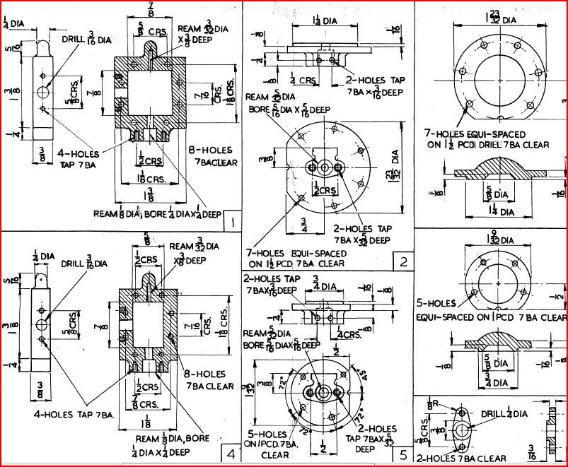
                Sarah, this is a typical bit of a Stuart drawing, there is no tollerance on the cylinder that goes with it just 1 1/4 dia

                typical stuart.jpg

                #265431
                Martin Connelly
                Participant
                  @martinconnelly55370

                  For the holes in a PCD you are getting towards the area where geometrical tolerancing is required on the drawing. Have a look at this tutorial on this subject. **LINK**

                  For the bore of a cylinder you could use ISO fits such as H11, see **LINK**

                  As stated earlier though all this is based on the assumption that you are mass producing parts at different times or locations that you want to be able to assemble without additional fettling. For the average hobby machinist working on their own making a one off or two off assembly they will make parts that match what they made the day /week/month/year before.

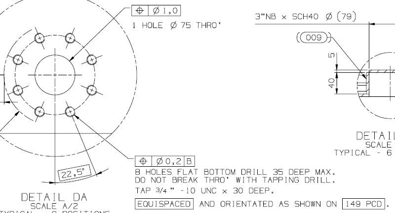
                  Do remember though that sometimes words are all that are required. I was looking at a drawing produced this month for real world engineering production that had some holes for studs with the note "Tapping drill must not break through".

                  Martin

                  #265432
                  Martin Connelly
                  Participant
                    @martinconnelly55370

                    Here is a clip from the drawing I referred to above, slight variance on the wording but the meaning is the same. Also a mix of metric and imperial dimensioning.

                    Martin

                    drawing example.jpg

                    Edited By Martin Connelly on 08/11/2016 13:45:12

                    #265435
                    Stephen Benson
                    Participant
                      @stephenbenson75261

                      Stuarts drawings are a nightmare, I would love to make several of their engines but the drawings are terrible to work to decimal inches no problem it is fractions I have a problem with could not be bothered to finish the SS50 I bought from them.

                      I know that lots of people on here seen it as a challenge and good luck to them I hope there are enough to keep Stuarts flourishing but model engineering is supposed to be fun I will stick to metric

                      #265436
                      SarahJ
                      Participant
                        @sarahj

                        Hi ,

                        Jason, I definitely think I'm capturing the Stuart sytle of drawing.

                        Martin, thanks for the links and the drawing with the notes. I will add some notes as I really hate it when I come back to a project after a big gap and I can't remember details or reasons for what I've already done. Which is all too common with me .

                        Also I've just started machining on the cylinder and realised that I've missed a dimension from my drawing for the spacing of the ports, ah well back to the drawing board

                        Regards,

                        Sarah

                        #265484
                        Neil Wyatt
                        Moderator
                          @neilwyatt

                          I think toleranced drawings can be the worst possible thing to give a beginner for several reasons.

                          Firstly they can be confusing and even intimidating.

                          More importantly, they lead the beginner to focus on exact dimensions in ways that slow them down and can even stop them progressing. An example could be a cylinder – how many people post worrying about reaming a cylinder for a steam engine because they need to get it an exact size? Or struggle to measure it accurately?

                          It's far more productive to tell someone to make the bore as close as they can to the specified dimension but to put their energy into achieving a good finish for the bore. The next step is to make the cylinder piston an appropriate fit using the bore as a gauge.

                          A good understanding of the whys and wherefores of fits is far more useful in the home workshop than an encyclopaedic knowledge of ISO tolerancing.

                          Very much my personal view and I know some will totally disagree.

                          Neil


                          Edited By JasonB on 08/11/2016 18:22:07

                          #265551
                          Neil Lickfold
                          Participant
                            @neillickfold44316

                            The Cox model engine maker used to make their engines so good that any piston could fit any bore if it was new. They were the exception for a long time. Neil Wyatt has hit upon a very important part in manufacturing. The service fit is far more important than the actual size in most cases, especially with a home built 1 off project. Making a piston to fit a bore is far easier than making a bore to fit a piston. Went through some old drawings from the 1960's for injection plastic moulds. They used both fractions and decimal inches down to 4dec places. On the parts that mattered it had a statement like 0.0002 clearance fit, or 0.0003 air vent etc On fraction dimensions they were to 1/64 inches unless otherwise stated. Nominal 1.0 inch dimensions were to +/- 0.01 inches, 0.01 inches +/- 0.002 0.001 inch +/- 0.001 inches all these were unless stated. So the drawings have notes all over like FIT or 0.0015 clearance etc.

                            Now days it is all metric with the ISO standard of fits and clearances , but on important parts, there is a note about the Fit or the detail pertaining to that part for it's function.

                            Neil

                            #265593
                            Circlip
                            Participant
                              @circlip

                              Same old question, How many thousand are you making? and are they for NASA? Industry and hobby are worlds apart. It matters not a jot whether you mix fractions, decimals or dogs danglies on the same drawings as long as the corresponding FITTED components match and forget geometric tolerancing and limits and fits. It's a toy engine so treat it as such and FIT the parts to suit. For the metric converters, metric for 1/2" IN TOY ENGINE TERMS is 13mm so don't expect a piece of 1/2" bar to fit without a fair bit of "Clearance"

                              Fell into the trap of "Company" oddities years ago when told the 1 1/2" "Machined" dimension I'd had some shafts made to at 1.500" dia. was wrong. A list of "Machined" sizes for shafts and bores was produced that bore no resemblance to the fractions stated as these were specific machining sizes for "Our" products, to ensure competitors bits (Chainwheels and Pulleys) couldn't be substituted for ours, thus ensuring an active Spares supply.

                              Regards Ian.

                              #265599
                              Martin Kyte
                              Participant
                                @martinkyte99762

                                NASA have been known to confuse metric and imperial before now. And signed and unsigned integers. (Height above planet is what?)

                                :0)

                                Martin

                                #265609
                                Muzzer
                                Participant
                                  @muzzer

                                  If you are going to attempt to get a workable fit between 2 components in the workshop such as an interference fit or a running fit, it's probably helpful to have an idea what tolerances are appropriate. With something like a press fit bearing, you aren't going to get a second chance and with a squishy part such as a sintered bush, the bore will reduce when you press it in to its hole. You need to take that data from the standards / manufacturer's info unless you insist on using trial and error – how long have you got?

                                  In my mind, home workshop practice is more akin to machine fitting than serial production. So you make stuff fit together and work rather than define components that must be made independently and fit flawlessly. Nothing wrong with that but on occasion (such as above), you have to also be an engineer ie design something with a degree of profound knowledge.

                                  Murray

                                Viewing 15 posts - 51 through 65 (of 65 total)
                                • Please log in to reply to this topic. Registering is free and easy using the links on the menu at the top of this page.

                                Advert

                                Latest Replies

                                Viewing 25 topics - 1 through 25 (of 25 total)
                                Viewing 25 topics - 1 through 25 (of 25 total)

                                View full reply list.

                                Advert

                                Newsletter Sign-up