Thanks for posting; interesting that they use a diaphragm rather than Bourdon tube. But I suppose the pressures are quite low. And diaphragms in aircraft instruments detect unbelievably small pressure changes.
Last night, at the fourth attempt, I've finally made a working Bourdon tube. It moves about 3/16" at 250psi, which is my intended full scale. It's not quite where I want, but having got one to work I can now fine tune wall thickness and material. I also need to design a better way of bending the flattened tube. Brass tends to kink rather than bend uniformly. I've just knocked up an embryo tube in copper, so we'll see if that is better behaved.
Or trying Henry Woods method in the latest ME, looks quite a good article and shows how he bends the tube made from 0.003" shimstock though I have just had a skim over it.
I hadn't considered electroforming, although I need a wall thickness of around 8 thou, which I suspect would take some time. At least in an amateur (my) environment.
In due course I will read the article In ME, when I get my copy. I vaguely recall an article in ME using shim for Bourdon tubes (probably in the 1970s) so I made two 'tubes' from 4 thou copper shim. The first one was a total disaster; couldn't remove the mandrel. The second one worked; briefly before the seam split. In its short life it was clear that 4 thou was far too thin a wall by the amount of movement trying to reach 20psi. Of course wrapping up from shim, with a lap joint, puts material just where you don't want it. So I prefer to use tube, thinned, flattened and rolled.
I am aware that Kozo has written on pressure gauges, but there appears to be no information on the internet. Of course I could buy the book(s), but they're expensive. And I suspect may take a different approach to me. I'm not really interested in descriptions of making pressure gauges, that's relatively simple. It's the engineering design of the components that interests me. Having said that, we have a Shay nut at the gliding club, so next time I see him I'll ask if he has any of the Kozo books.
Andrew wont be able to read this because he has blocked me, but the Master of miniature pressure gauges was Freddie Dinnis. All his were individually calibrated and made of proper drawn phos bronze of 'D' section.
I really cannot see how someone making them out of brass shimstock can be the correct way to go or deserves paying for an article by ME. I have a drawer full of old miniature gauges with brass bourdon tubes, some of the shimstock variety, and all were given to me because the brass bourdon tubes had corroded. This was was not dezicincification but corrosion.
Roy Amesbury described how to make them properly in ME, though a different approach from Freddie Dinnis, in ME 1973/4.
Andrew – you really need to read Kozos' pressure gauge articles, as he explains how he rolls the tubes out of bronze, and how he silver solders them. And, how he makes the dead weight tester, and…
Now, I can absolutely understand one wanting to figure it out for oneself, but I can almost – ALMOST – use the name "Kozo Hiraoka" and "Cherry Hill" in the same paragraph.
The books really are not that expensive, and, if you find a used one, you can always sell it on later and you have probably not lost anything, but gained lots.
If you want to know which books contain pressure gauge articles in the back, just ask and I'll dig what books of his I have out, and I'm sure others would, too.
The reason for writing this note is that you do really impressive work, and I want to see you progress faster, so it is a bit selfish on my part…
The Freddie Dinnis type has not. At various times I have mentioned Freddie on here.
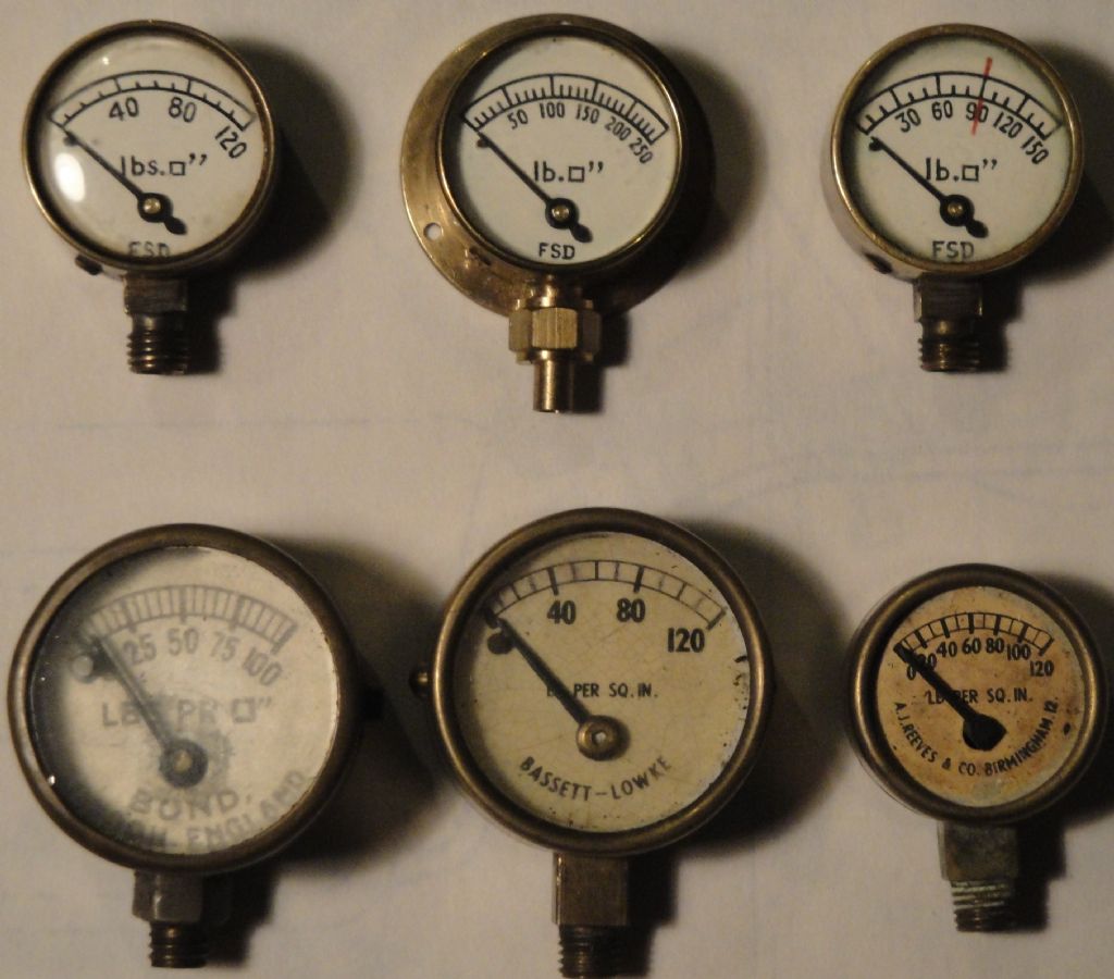
Ask any decent miniature loco builder what pressure gauge he wants on his loco and they will say a Freddie Dinnis (FSD) gauge. They were so good they were used by Rolls Royce.
All
All the bottom row in the above pic have corroded bourdon brass tubes. The top row are all Freddie Dinnis (FSD) gauges.
Here you go – the pressure gauge build is in Kozo Hiraoka's Climax book, back pages. I think it's also described in his Heisler book (in inches) and, probably in Live Steam magazine.
I do have the ME articles in my files – all are good designs, by master craftsmen – but what Kozo Hiraoka brings to the table is a clear description of the manufacturing process that lets those like me follow along.
Camden sells the Kozo books – here's a link to the Climax book:
The Freddie Dinnis type has not. At various times I have mentioned Freddie on here.
Ask any decent miniature loco builder what pressure gauge he wants on his loco and they will say a Freddie Dinnis (FSD) gauge. They were so good they were used by Rolls Royce.
.
Yes, Julian … you posted that back in November **LINK**
I mean no offence to you, or to Mr. Dinnis; but I do not understand why the fact that he made good things one way should preclude others from considering alternative methods.
That said … I choose to abstain from further debate of the matter.
MichaelG.
.
P.S. for convenient reference, here is Bourdon's patent:
Michael: Thanks for posting the link to the original Patent; very interesting. There are some pretty amazing things made using electroforming. It'd be interesting to experiment, but I really need to stop getting diverted!
I have now read the recent pressure gauge article in ME and, thanks to a kind offer from a forum member, have also read the relevant pages by Kozo. In some ways they are similar, but crucially have different methods of forming and soldering the Bourdon tube. I also did a search on Dinnis. No doubt he made very nice pressure gauges, but none of the above made what I am trying to achieve.
My traction engines are 4" scale so the pressure gauge is going to be around 1¾" diameter, so possibly a little larger than most miniature ME gauges. My engines run at 170psi so I need a gauge with a FSD of around 250psi, rather higher than most locos. Both of these factors mean that I should be able to get away with making a Bourdon tube from drawn tube rather than folding and soldering shim, based on the mathematics of Bourdon tubes and practical experience.
The other important issue is that I am not interested in a gauge where the scale is only about a 30° arc. I want to make one with the needle pivot central and a scale arc of around 270°. That requires a much higher 'gain' from Bourdon tube to pointer, which I think requires a simple gear train. I'm not sure what DP yet, but probably around 80DP, which should be an interesting challenge. I suspect that if I want involute gears (as opposed to cycloidal) I'll need to make my own cutters.
Andrew
Could you not source some gears from an old (French) clock or possibly a watch? Or is that a sacreligious suggestion?!
A local fellow makes replacement gauges, or "fixes" old gauges for full size steam, including CPR 2839 (which will never move) and CPR 2816, and…
What he does is take commercial gauge innards, and places them in cases he makes, with dials and hands he engraves.
What that gives are gauges that look the part, but actually work.
At first, I was agast that someone would do that, but – these steam locomotives actually work, and need gauges that are accurate and reliable first and foremost, and should look the part as a secondary consideration.
(apologies if this is old news to you, or a path you have decided NOT to go down – the coffee's brewing and not doing its job quite yet!)
Just thought this might be useful info for anyone contemplating making their own gauges.
Dave
The Emerald Isle
I've done this for my bench boiler, it happily reads up to about 35 psi+ FSD once I took the ring that 'stiffens' the action out. I red lined it at 30PSI which is more than ample for my small stationary engines. Against my expensive (but not certificated) gauge it seems to have good repeatability.
Most fire extinguisher ones have bourdon tube in and I think the only way to reduce their FSD would be to change the pivot etc. I think this could affect accuracy and sensitivity.
I think we are rather straying off how the best commercial and amateur makers made these gadgets in miniature.
It would help if John Alexander Stewart would provide links for Kozzo he quoted.
With the greatest of respect , the topic is actually the conversion of fire extinguisher gauges, rather than the continued celebration of the work of Fred Dinnis.
I do wonder if Mr Dinnis would have been rather quicker to encourage rather than disparage the efforts of others.
And just to derail the thread further I was looking at an old ME yesterday and there was a write up on a Bourdon Engine. Used a Bourdon tube as a single acting "piston" with one end connected to the conrod, the other to a simple valve to fill or empty the tube.
Fortunately I'm not building a loco, so I can ignore the exhortations of our resident expert.
Thanks for the gear cutter links and ideas. PPThornton list cutters down to 0.1mod, but I'm pretty sure they're all cycloidal form, for use in clocks.
I hadn't considered using the innards of a commercial gauge; I guess the issue might be finding one that is small enough?
I had considered using watch parts for the gears and hands, or even old aircraft instrument parts. The problem is not only finding what I need, but two sets of same. There are jumbo packs of watch parts available but what you get is what you get, not necessarily what you need.
There's another possible issue. In order to get high angular 'gain' through the gear train the pinion needs very few teeth, probably 8 or 10. In theory, even for 20°PA, that means undercut teeth, so you lose the conjugate action for part of each tooth engagement. The problem can be cured by using a different PA, say 30°. But for that one would have to make cutters.
Being a paid up member of the awkward squad part of the fun is to see if I can design the gears, make the small cutters and then cut the gears so that they mesh smoothly with minimal backlash.