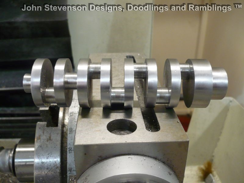
milling crankshaft on cnc mill using A axis
milling crankshaft on cnc mill using A axis
- This topic has 35 replies, 12 voices, and was last updated 31 March 2021 at 21:30 by
 Retired Barry.
.jpg")


- Please log in to reply to this topic. Registering is free and easy using the links on the menu at the top of this page.
Latest Replies
-
- Topic
- Voices
- Last Post
-
-
How to identify a thread, ACME vs TR
Started by:
moonman
in: Beginners questions
- 11
-
7 February 2025 at 12:55
Bazyle
-
Alibre Workshop/Meshcam pro
Started by:
Ian McVickers
in: CNC machines, Home builds, Conversions, ELS, automation, software, etc tools
- 5
-
7 February 2025 at 11:48
Ian McVickers
-
ZYTO mini Lathe – need help!
Started by:
theshonkymachinist
in: Beginners questions
- 10
-
7 February 2025 at 11:46
Roderick Jenkins
-
speed control dc motor problem.
Started by:
mark smith 20
in: Workshop Tools and Tooling
- 2
-
7 February 2025 at 10:57
mark smith 20
-
What Do These Mean; Why So Many Loop Errors? (Alibre Atom)
Started by:
Nigel Graham 2
in: CAD – Technical drawing & design
- 5
-
7 February 2025 at 10:20
Nealeb
-
Parting off – Left over nib
Started by:
Blue Heeler
in: Workshop Techniques
- 7
-
7 February 2025 at 09:48
JasonB
-
Eastern European Steam
Started by:
parovoz
in: Introduce Yourself – New members start here!
- 11
-
7 February 2025 at 08:27
james rumble
-
A New Scam Format?
Started by:
Nigel Graham 2
in: The Tea Room
- 6
-
7 February 2025 at 07:05
Diogenes
-
OKMO Microcosm Model M31 Vertical Steam Engine Single Cylinder with DIY Mods
Started by:
Blue Heeler
in: Stationary engines
- 1
-
7 February 2025 at 01:07
Blue Heeler
-
Solid Edge – Spring Designer – Help!
1
2
Started by:
SillyOldDuffer
in: CAD – Technical drawing & design
- 7
-
6 February 2025 at 17:51
SillyOldDuffer
-
New member – hobby engineer
Started by:
zymurgy2289
in: Introduce Yourself – New members start here!
- 3
-
6 February 2025 at 17:06
zymurgy2289
-
Drill press will not start
Started by:
AStroud
in: Help and Assistance! (Offered or Wanted)
- 13
-
6 February 2025 at 16:57
Andrew Tinsley
-
Lidl spray aerosol items
1
2
Started by:
Bootlegger Blacky
in: Hints And Tips for model engineers
- 20
-
6 February 2025 at 16:53
Mick B1
-
Totally unacceptable treatment
1
2
Started by:
Me.
in: General Questions
- 14
-
6 February 2025 at 15:49
John Hinkley
-
Changes to Well-Known Auction Site
1
2
Started by:
Chris Crew
in: The Tea Room
- 21
-
6 February 2025 at 13:48
Tony Pratt 1
-
Vickers Inverted Engine
Started by:
JasonB
in: Stationary engines
- 9
-
6 February 2025 at 13:14
JasonB
-
CAD – Target Enigma
1
2
3
4
Started by:
SillyOldDuffer
in: CAD – Technical drawing & design
- 17
-
6 February 2025 at 11:36
SillyOldDuffer
-
The most difficult project?
Started by:
Tony Martyr
in: Stationary engines
- 5
-
6 February 2025 at 11:25
Chris Gunn
-
Brian’s 1″ Minnie Traction Engine
1
2
…
13
14
Started by:
Brian Abbott
in: Traction engines
- 38
-
6 February 2025 at 10:55
Brian Abbott
-
Small butane torch refilling.
Started by:
YouraT
in: Workshop Tools and Tooling
- 13
-
6 February 2025 at 08:21
Nicholas Farr
-
Calling all Little John and other Raglan users
Started by:
David Senior
in: General Questions
- 1
-
6 February 2025 at 07:17
David Senior
-
CNC mill on its stand
Started by:
Dave S
in: CNC machines, Home builds, Conversions, ELS, automation, software, etc tools
- 2
-
6 February 2025 at 06:54
JasonB
-
shopmade single flute end mill
Started by:
celso ari schlichting
in: General Questions
- 4
-
6 February 2025 at 06:34
Diogenes
-
Pittler spiral cutting test
Started by:
vic newey
in: Workshop Techniques
- 9
-
5 February 2025 at 20:16
vic newey
-
Pennsylvania A3 Switcher
1
2
3
Started by:
Mark Elen 1
in: Work In Progress and completed items
- 18
-
4 February 2025 at 17:52
Mark Elen 1
-
How to identify a thread, ACME vs TR
Latest Issues


Newsletter Sign-up
Latest Replies
- How to identify a thread, ACME vs TR
- Alibre Workshop/Meshcam pro
- ZYTO mini Lathe – need help!
- speed control dc motor problem.
- What Do These Mean; Why So Many Loop Errors? (Alibre Atom)
- Parting off – Left over nib
- Eastern European Steam
- A New Scam Format?
- OKMO Microcosm Model M31 Vertical Steam Engine Single Cylinder with DIY Mods
- Solid Edge – Spring Designer – Help!

