Milling a 45 degree ‘v’ slot

Advert

Milling a 45 degree ‘v’ slot

Home Forums Workshop Techniques Milling a 45 degree ‘v’ slot

Viewing 25 posts - 26 through 50 (of 68 total)
  • Author
    Posts
  • #473475
    JasonB
    Moderator
      @jasonb

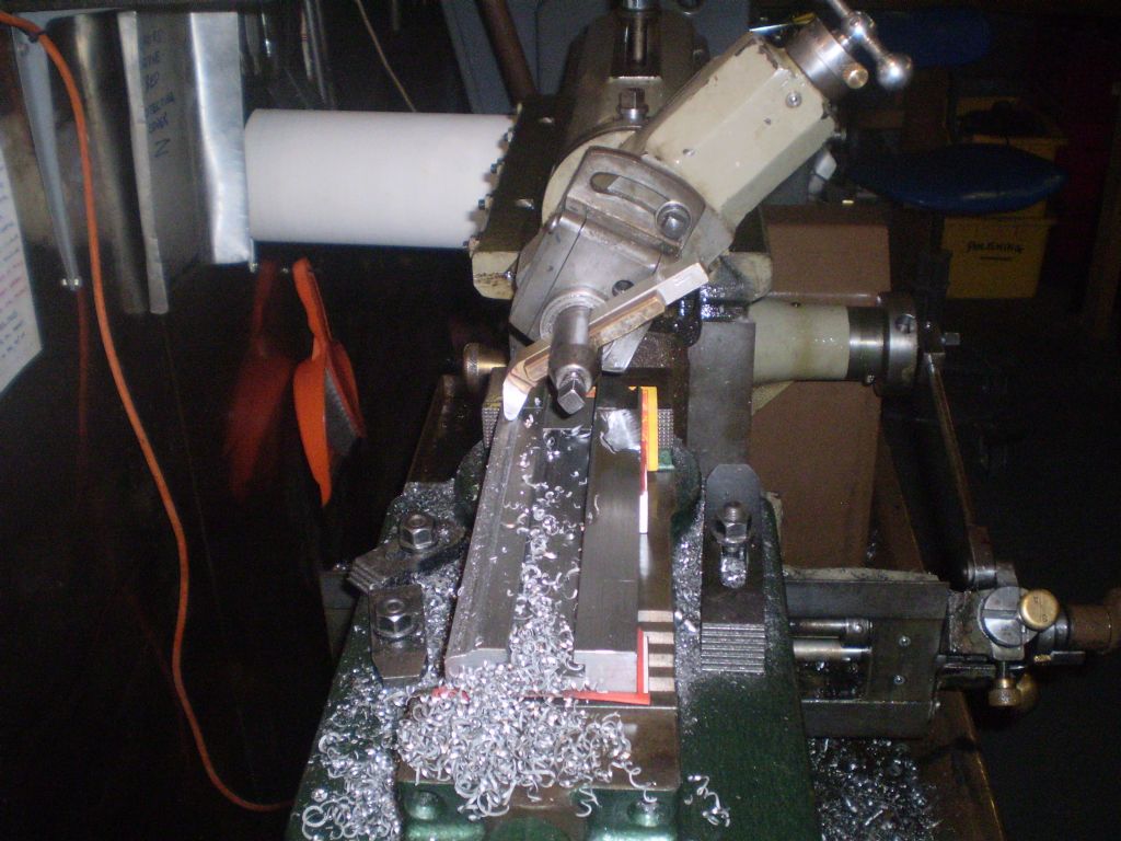
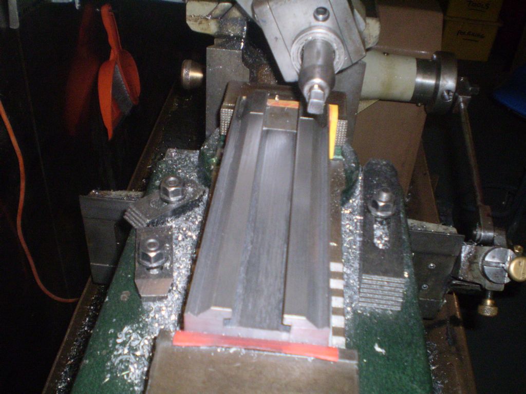
      If it is not too late rig up some form of stop against one side of the work, left would seem best. That way you can turn the work 180 degrees to do the other side which I think would be better than tilting the head the otherway.

      You can then repeat the cuts on the other side to the same settings (which you made a careful not of) and have a good chance of getting a similar cut either side. If the width ends up a bit large then take half off one side and flip again to keep the cuts symmetrical as you work your way down to the required measurements, scribed line is best used as a guide for parts that need to fit accurately like this..

      If it woks on this one then do them all before hanging the head position to do the Tee slot but keep the vice and stop in position.

      Advert
      #473480
      Lee Jones 6
      Participant
        @leejones6
        Posted by Michael Gilligan on 21/05/2020 08:10:26:

        Go for it, Lee …

        ‘though it’s interesting to ponder how much simpler it would be to cut the vees on a shaper.

        Fair comment. I'll just nip out and get one. laugh

        #473483
        Lee Jones 6
        Participant
          @leejones6

          Thanks Tony. That's the plan (although I'm still relying on Morris the moose to make good).

          I've already taken the work out of the vice Jason.

          Plan is to flip the work. I have taken notes of the *relative* measurements.

          #473493
          John Baron
          Participant
            @johnbaron31275
            Posted by Michael Gilligan on 21/05/2020 08:10:26:

            Go for it, Lee …

            ‘though it’s interesting to ponder how much simpler it would be to cut the vees on a shaper.

            MichaelG.

            +1

            #473496
            JasonB
            Moderator
              @jasonb
              Posted by Michael Gilligan on 21/05/2020 08:10:26:

              Go for it, Lee …

              ‘though it’s interesting to ponder how much simpler it would be to cut the vees on a shaper.

              MichaelG.

              I the user has even less idea of how to use a shaper than they do about using a milling machine I wonder too.smile p

              Otherwise an ideal machine for the job in the right hands.

              Edited By JasonB on 21/05/2020 10:06:12

              #473497
              John Baron
              Participant
                @johnbaron31275

                Hi Lee, Guys,

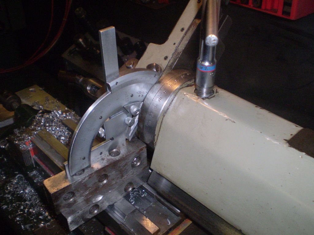
                Two things here, first it is almost impossible to accurately set the head at an angle of 45 degrees, which you will find out when you come to mate it up with the face that it is supposed to fit.

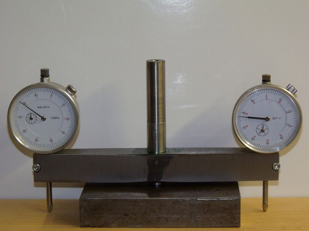
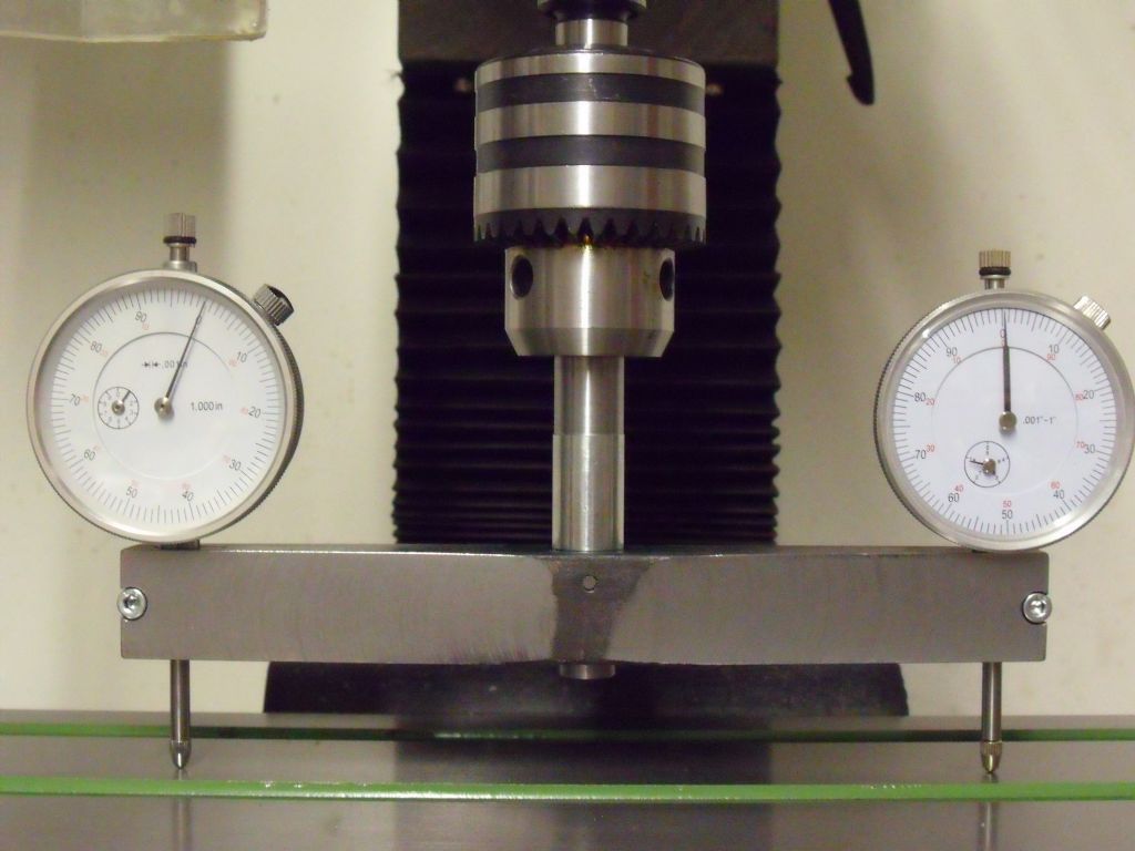
                Second when you come to re-tram the head you will find that as soon as you tighten the securing bolts the head will move slightly. I've spent hours tramming the head on my mill and whilst it is now nearly spot on you will find that the tram moves as soon as you tighten the head locks. Not only that but the tram will change with the position of the head on the column.

                I even went as far as making a tramming tool that gets me spot on ! Until I tighten something up.

                Edited to add pictures

                Tram tool 12.jpg

                Here its just sat on a steel block.  Since this picture the dial gauges have been changed for a pair of 0.01 mm identical ones.

                Tram tool 15.jpg

                This picture shows it in use. The out of tram is quite obvious, nearly 5 thou.  Using this tool I can get 1/2 a thou sometimes.


                Edited By John Baron on 21/05/2020 10:17:42

                #473499
                Buffer
                Participant
                  @buffer

                  I have often wondered how you are supposed to acurately position a V on work with a head tipped over or even with the work tipped over. None of the usual edge finding techniques that I know of would work.

                  #473500
                  John Baron
                  Participant
                    @johnbaron31275
                    Posted by Buffer on 21/05/2020 10:14:49:

                    I have often wondered how you are supposed to acurately position a V on work with a head tipped over or even with the work tipped over. None of the usual edge finding techniques that I know of would work.

                    Actually its quite easy. Scribe lines to represent the centre line and "V" edges and work to those.

                    #473501
                    thaiguzzi
                    Participant
                      @thaiguzzi
                      Posted by Michael Gilligan on 21/05/2020 08:10:26:

                      Go for it, Lee …

                      ‘though it’s interesting to ponder how much simpler it would be to cut the vees on a shaper.

                      MichaelG.

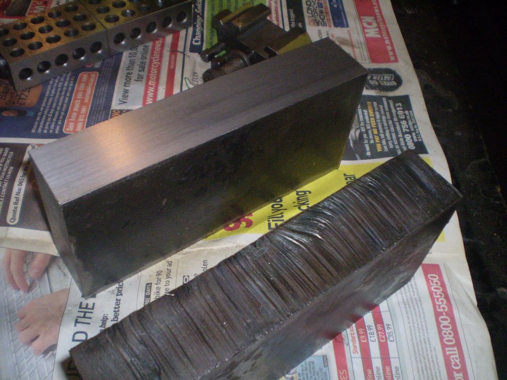
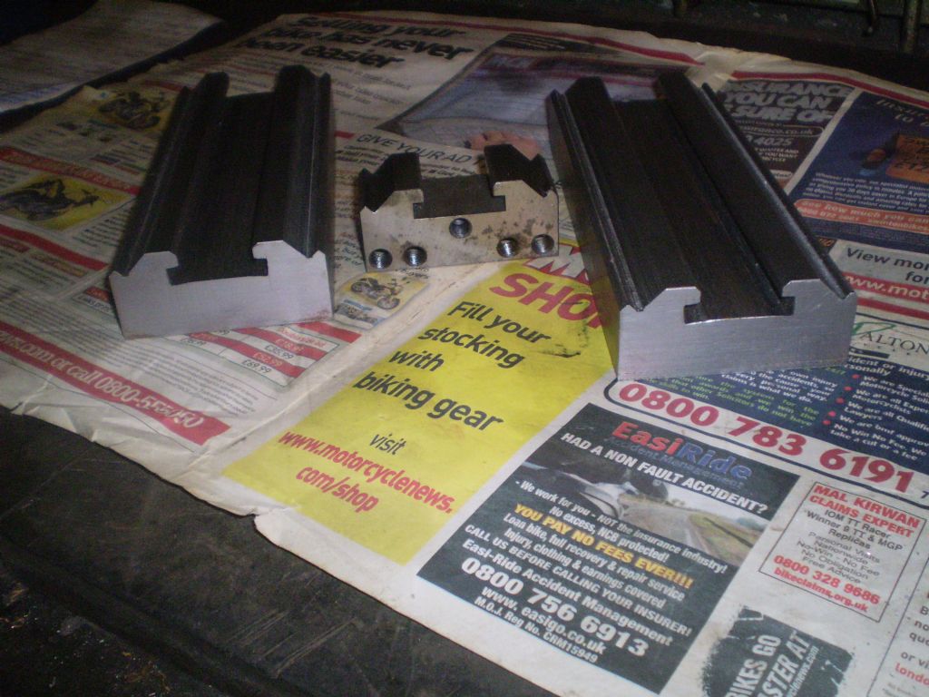
                      june - nov 2014 123.jpg

                      june - nov 2014 124.jpg

                      june - nov 2014 133.jpg

                      june - nov 2014 135.jpg

                      june - nov 2014 138.jpg

                      june - nov 2014 143.jpg

                      #473509
                      Lee Jones 6
                      Participant
                        @leejones6

                        Show off. laugh

                        Don't suppose you want to make me some, do you? smile p

                        Edited By Lee Jones 6 on 21/05/2020 10:51:14

                        #473513
                        thaiguzzi
                        Participant
                          @thaiguzzi
                          Posted by Lee Jones 6 on 21/05/2020 10:50:32:

                          Show off. laugh

                          Don't suppose you want to make me some, do you? smile p

                          Edited By Lee Jones 6 on 21/05/2020 10:51:14

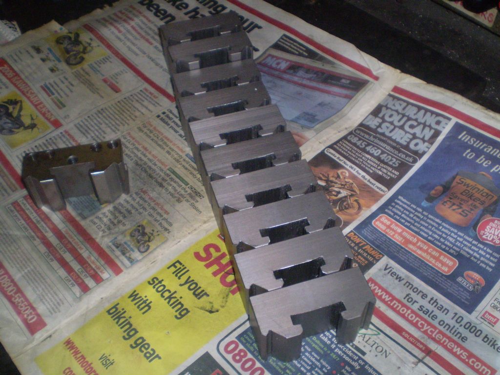
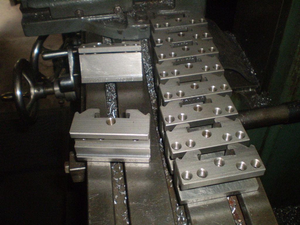
                          That was a block of steel to make 5.

                          No probs in making some more, but the postage back to Blighty could sting a bit…..

                          june - nov 2014 068.jpg

                          june - nov 2014 146.jpg

                          june - nov 2014 161.jpg

                          june - nov 2014 198.jpg

                          #473515
                          Lee Jones 6
                          Participant
                            @leejones6

                            That's my plan, although I'm limited to 4 at a time with my set-up.

                            It's okay, I was only jesting.

                            My plan is to make say 4 or 8 of my own and buy some from knock-offs when they come back in stock.

                            Yours look amazing by the way.  Are they T1s or T2s?

                            Edited By Lee Jones 6 on 21/05/2020 11:00:48

                            #473516
                            Martin Connelly
                            Participant
                              @martinconnelly55370

                              You do realise that the two vees are only there so that the holder can be used from both ends don't you? In reality a single vee at one end and a flat at the other will work as well as long as the vee is at the end the tool sticks out of. The two vees is actually bad tooling practice. The other issue with these tool holders is that in some of them the plunger does not pull in far enough to over centre and toggle, relying instead on friction alone to stop the holder coming loose in use.

                              Martin C

                              #473517
                              Clive Foster
                              Participant
                                @clivefoster55965

                                Lee

                                It may not be obvious but the Dickson toolpost & toolholder design is technically over-constrained with more locating surfaces than are strictly needed. There are engineering reasons but of a sort which folk line us don't need to worry about.

                                I would forget about accuracy on the outside Vee face and simply set things up so as to get the best possible finish on the wide, inner, Vee face cutting a little deeper so the outer Vee face is in the wind. Interestingly the wear, polish actually, marks on my factory Dickson / Rapid posts are on the outer Vee not the inner suggesting that maybe thats where location occurs. I really ought to blue things to find out what touches where, but life is short! However the inner Vee face is probably easier to cut and clearly equally functional. The narrower outer ones could be done with a smaller, cheaper, cutter tho'. Whatever works.

                                With several to do I'd not mess around with a vice or trying to tram the head at 45°. Use what you have and make a simple sturdy sine plate jig with a solid fence and clamps to hold the work in the right place. Forget angles, too fussy and we home shop types don't need to spend on the super accurate measuring equipment to get it really right.

                                Do it the old fashioned way by slope. An accuracy of one thou at one foot, or the metric equivalent, is well within ordinary capabilities and corresponds to about 1/20 th of a degree, 3 minutes of arc. No way will you tram a head to that sort of accuracy. If you have a decent DRO set up making an accurate sine plate is a piece of cake as is making a one time use block to get the angle.

                                We home shop types tend to fight a little shy of one time jig "disposable" tooling and tend to spend money on versatile equipment that can do lots of things which, mostly, never actually happen.

                                DRO sets really are a game changer here.

                                I'd expect to make up a sine plate style jig in less time than it takes to set up the head tram and vice. Takes a little longer but more useful to make the plate face a grid of tapped holes style, 1/4" or 6 mm in 5 spot dice in 1" or 25" square base pattern will hold anything we want to make. Stamp the riser block with the thickness / angle and pop it in box should you ever need it again. Probably will at 45°. Different angle. Make an new block just like that. I have nice gauge block sets and a fancy 3 way sine plate style stack but for all reasonable use a DRO will cut one to whatever size you need to set the sine plate when you need it.

                                Obviously set the fence so you can just flip the job to do the opposite Vee in the right place with the vertical head travel on the same DRO number or, better, hard stop.

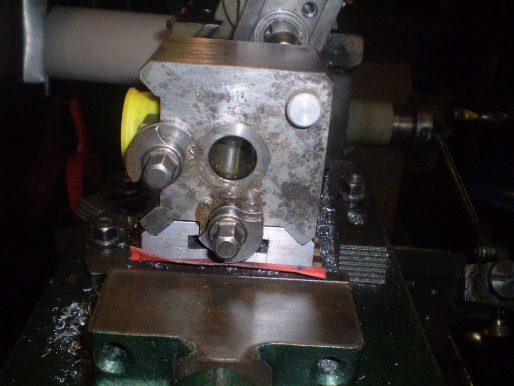
                                The T shape slot in the back is hard to cut and harder to get in the right place. I'd cheat. Cut a plain slot then screw and glue the flanges on. Check that the slot depth is right before gluing. Having done number one lock the head setting for the finish cut on all the others. Theoretically its not as strong as factory carved from solid but I seriously doubt if anyone could prove weakness in practical use.

                                When you finish machine the tool slot it may well be easiest to dismount the tool post, lay it on its side on the mill table and use it as a jig to mount the holder for final machining. That way you know the slot floor is correctly aligned. I'd clamp the base of the new holder against a fence on the table which would work fine if you machine that face on the block first and use as the reference for all subsequent one.

                                Hafta say that if you are using carbide inserts there is much to be said for making some fixed holders with no adjustments for use with the insert holders only. With a good set-up and efficient machining habits 8 holders is as easy to make as 4.

                                Clive

                                #473518
                                John Baron
                                Participant
                                  @johnbaron31275
                                  Posted by thaiguzzi on 21/05/2020 10:22:58:

                                  Posted by Michael Gilligan on 21/05/2020 08:10:26:

                                  Go for it, Lee …

                                  ‘though it’s interesting to ponder how much simpler it would be to cut the vees on a shaper.

                                  MichaelG.

                                  june - nov 2014 123.jpg

                                  june - nov 2014 124.jpg

                                  june - nov 2014 133.jpg

                                  june - nov 2014 135.jpg

                                  june - nov 2014 138.jpg

                                  june - nov 2014 143.jpg

                                  Nice !

                                  #473520
                                  Lee Jones 6
                                  Participant
                                    @leejones6

                                    Blimey.

                                    Thanks for taking the time to draft that Clive.

                                    I'm going to need some time to digest all of it (do you have pictures? laugh).

                                    #473523
                                    Clive Foster
                                    Participant
                                      @clivefoster55965

                                      Hi Lee

                                      Sorry no pictures. Not something I've done but its the way I'd do it if I had to.

                                      Just one of several fairly complex things that folk do on a fairly regular basis that, for a long time, have make me think "must be an easier way".

                                      Its easy to forget that what you are trying to do is make a functionally effective toolholder. If copying factory is too hard then cheat!

                                      I should thank you for providing the opportunity to get off my tail and finally putting my thoughts all together in coherent fashion. I will say that it wasn't until I was about half way through that I cottoned on to how much a DRO can be a game changer in the real world. I'd pretty much always "sort of known" but I've got the gear to do it the old style way. Lots and lots of ££££ over several decades worth.

                                      Clive

                                      #473526
                                      Lee Jones 6
                                      Participant
                                        @leejones6

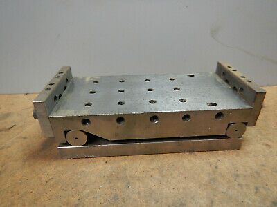
                                        This is what I have in my head.

                                        image.jpg

                                        In what way would you use the DRO to build the sine plate?

                                        #473537
                                        Tony Pratt 1
                                        Participant
                                          @tonypratt1
                                          Posted by John Baron on 21/05/2020 10:05:44:

                                          Hi Lee, Guys,

                                          Two things here, first it is almost impossible to accurately set the head at an angle of 45 degrees, which you will find out when you come to mate it up with the face that it is supposed to fit.

                                          Second when you come to re-tram the head you will find that as soon as you tighten the securing bolts the head will move slightly. I've spent hours tramming the head on my mill and whilst it is now nearly spot on you will find that the tram moves as soon as you tighten the head locks. Not only that but the tram will change with the position of the head on the column.

                                          Actually fairly easy to get the head to 45 degrees using a sine bar set to that angle & a DTI, basically you 'tram ' the sine bar.

                                          All heads will move when the bolts are tightened so you have to allow for that movement so when the bolts are tightened up fully they move the head into the correct position.

                                          Tony

                                          #473557
                                          Paul Fallert
                                          Participant
                                            @paulfallert28101
                                            Posted by Martin Connelly on 21/05/2020 11:00:53:

                                            "You do realise that the two vees are only there so that the holder can be used from both ends don't you? In reality a single vee at one end and a flat at the other will work as well as long as the vee is at the end the tool sticks out of. The two vees is actually bad tooling practice." Martin C.

                                            ——

                                            Observation: The two vees vs one vee question came up when Haro!d Hall (HH) presented his simplified "easy" toolholder design (although his was not a vee, it was one half-round and a flat). Tests proved the repeatability of HH toolholders. I have found the real value in having a QCTP is in having many dedicated toolholders. HH design made that possible using simple tools (no shaper, no dovetail cutters, no tramming, no math, etc).

                                            Paul

                                            #473564
                                            Martin Connelly
                                            Participant
                                              @martinconnelly55370

                                              John Reese, that matches with some of my bought toolholders which have a slot at the bottom of the vee. This is not necessary from a fit point of view as the peaks of the vees on the tool mount are truncated.

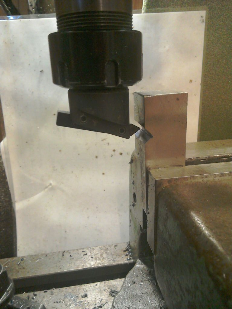
                                              It does remind me of gashing a blank before cutting teeth on a gear using a form tool. I am starting to think that a form tool used like a fly cutter would be a relatively simple set up compared to all the messing around with angle plates, tilted head or special jigs. For a beginner grinding a HSS blank to two 45 degree faces should be quite simple, a home made holder based on a small fly cutter but not angled is an easy tool to make and there are lots of how to videos on using these types of tools to make gears. Spacing the vees becomes relatively simple as a result provided the tool is stiff enough for the necessary stick out for the two vees to be cut with just a move of the quill.

                                              Martin C

                                              Been out and mocked up this as an example.

                                              img_20200521_141928.jpg

                                              Edited By Martin Connelly on 21/05/2020 14:23:04

                                              #473572
                                              John Baron
                                              Participant
                                                @johnbaron31275

                                                Hi Guys,

                                                I notice that nobody has commented about my suggestion of using a 45 degree countersink. HSS or Carbide.

                                                Using one would mean that the work could be securely fastened down to the mill table without any messing about with the mill head and then having to tram it all up again.

                                                #473577
                                                John Baron
                                                Participant
                                                  @johnbaron31275

                                                  Hello Martin, Guys,

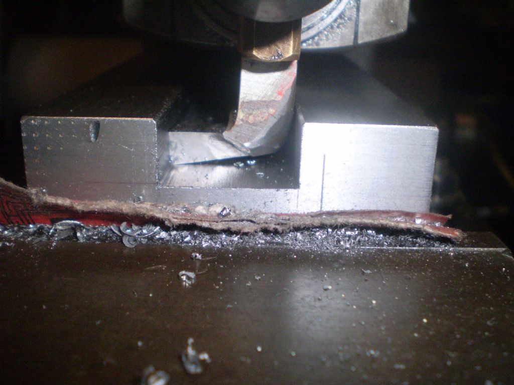
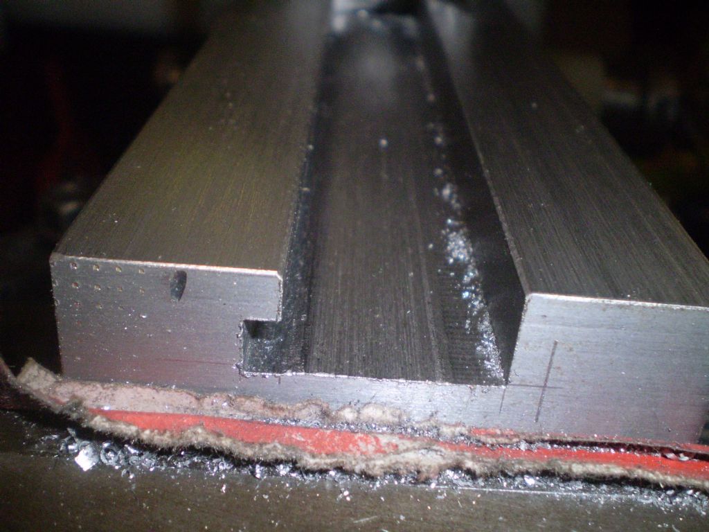
                                                  That is basically how I cut the dovetails for this slide.

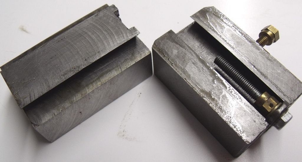
                                                  26-01-2018014.jpg

                                                  #473578
                                                  Martin Connelly
                                                  Participant
                                                    @martinconnelly55370

                                                    John, had to go back to page 1 to find it, I didn't see it because I was busy in the garden most of yesterday and never looked at the posts from then. It seems like a good idea to me. As in all these things there are probably hundreds of ways to do it and it's going to be up to the OP to decide what he can do and wants to do to get the work done. All we can do is suggest options until he decides on something.

                                                    Martin C

                                                    #473581
                                                    Clive Foster
                                                    Participant
                                                      @clivefoster55965

                                                      Lee

                                                      Got it in one!

                                                      The point about using a DRO is that it makes it pretty much routine to get the spacing of the two rods and the ledges they butt up against correct to any practical level of accuracy. Its equally easy to make the riser block required for whatever angle you want to sufficient accuracy.

                                                      Equally getting a nice regular pattern for the tapped holes is almost trivial. Consider locating dowel fittings to get the fence square or make the fence L section so the working part is above the table and trim it dead square in situ.

                                                      Plenty of variations on the theme to get the best balance between what material you have on hand, what machining facilities you have and what you plan to do. I'd probably make flat bottom Vee carriers for the rods with bolt holes to fix to the table or riser. Rods sticking out about 1" each side for clamps. Except for very shallow ones risers are probably most convenient to handle if made with tapped holes in top and bottom. Top ones take the Vee trough for the rod, bottom ones hold a plate extending either past the ends or to one side drilled so it can be bolted to the table. Shallow ones would need the fixing plate and riser made in one.

                                                      I'd make the riser in situ. Start with some stock a bit too deep, fit bolt holes, fix to base, bolt on machine table and cut it exact to size. Fit Vee troughs and sine plate and get to work.

                                                      Or you could make a complete unit on its own baseplate like the one in your picture. Invert it to bolt the riser on. Simply clamping the rods to a flat top ought to be satisfactory. Especially if you use the proper sine plate layout with deep ledges. Although I'd go for shallow ledges and a Vee trough but realistically its 6 of one half a dozen of the other.

                                                      Being a lazy type I'd probably base the device around a drilled and tapped 1/2" thick alloy breadboard from optical suppliers like Thor Labs **LINK** . The smaller ones aren't too silly spendy but double density versions might be a little too much. Something in the 8" x 8" to 10" x12", 200 x 200 mm to 250 x 300 mm might suit. The anodising is tough. Some stiffening underneath would be desirable for most jobs. Glued on strips perhaps.

                                                      The drilled and tapped breadboards are roughly comparable in price to 1" aluminium tooling plate or ordinary 25 mm steel plate so its not an unreasonable way to go about things.

                                                      So DIY "all new" you are in a similar price range to an import 4" tilt and swivel vice or a bit more than a swivel 6" vice. Much, much less if your finder-fu is good on used and handy scrap.

                                                      Its what I would do if starting out saving maybe £3,000 on stuff I'd most likely no longer need to have. Probably half of which I've not exploited. My finder-fu is usually pretty good too.

                                                      With a bit of creativity in the fence line, think limitless vice and carved in situ style, a device like this can make a larger machine vice unnecessary. If one piece style you can take it to the bench for preliminary set up too, of-times on a smaller mill the head gets in the way.

                                                      Clive

                                                    Viewing 25 posts - 26 through 50 (of 68 total)
                                                    • Please log in to reply to this topic. Registering is free and easy using the links on the menu at the top of this page.

                                                    Advert

                                                    Latest Replies

                                                    Home Forums Workshop Techniques Topics

                                                    Viewing 25 topics - 1 through 25 (of 25 total)
                                                    Viewing 25 topics - 1 through 25 (of 25 total)

                                                    View full reply list.

                                                    Advert

                                                    Newsletter Sign-up