Mill Wobble

Advert

Mill Wobble

Home Forums Manual machine tools Mill Wobble

Viewing 25 posts - 26 through 50 (of 59 total)
  • Author
    Posts
  • #466390
    Neil Lickfold
    Participant
      @neillickfold44316

      Use a marker pen, on the outside of the spindle. Mark where the high side is and the low side and 1/2 way between. Now keep rotating, to see if it is consistently high on the high side and low on the low side. If it is, then the bearing is unlikely the cause. You can tilt the head over, and reskim the inner taper of the spindle to get it true on the front taper. If you snug the gibs and raise and lower the column, should be able to make it as round as the concentricity of the spindle bearings. The more difficult part to test is the concentricity of the parallel register, further up inside the spindle. If that has a run out of 0.02mm, that error will show about 75mm below the spindle .

      Neil

      Advert
      #466427
      not done it yet
      Participant
        @notdoneityet

        I have a chinese morse taper that is not the correct angle. I suspect (even expect) there might be some chinese sockets that are similarly inaccurate.

        Mine ‘easily rattled’ after fitting to a proper morse socket such that blueing was totally unnecessary to diagnose the fault. Lesser inaccuracies in a socket would show up as lesser faults than the carp I got. It may just be that sort of case with this machine. Time for using some engineer’s blue I might suggest?

        Clearly not quite so easy on a socket such as an R8 than a Morse taper🙂

        #466438
        Michael Gilligan
        Participant
          @michaelgilligan61133
          Posted by Iain Downs on 22/04/2020 15:25:29:

          […] 'everyone knows R8 is better'.

          .

          ‘everyone’ is right, Iain … insofar as that ^^^ statement goes

          BUT ‘everyone’ also knows that re-working a product requires some design effort.

          [ rather than some ill-considered bloating of a specification for marketing purposes ]

          Evidently, the group ‘everyone’ does not include some of our suppliers crying 2

          Sorry

          MichaelG.

          #466779
          Iain Downs
          Participant
            @iaindowns78295

            I got out to the shed last night for some more measurements, but unfortunately (?) I was mugged by a bottle of wine on the way back in and failed to report!

            I looked at the runout on the 50mm face mill. On the body of the mill I saw 30 microns, On the arbor I saw 10 microns and on the spindle 6 microns.

            A less capable indicator inside the spindle showed about 3 or 4 microns – barely a twitch on a 0.01mm indicator.

            I also put a spot on the point on the rotation of all (body, arbor, inside spindle and outside spindle) of a minimum and they were reasonably in line.

            I tried again with the 20mm bar. This time (for variety) with the 3rd of the 20mm collets I own. Before I installed this, though I backed the set screw out half a turn or so and the drawbar screwed up nicely. At 100mm down from the spindle I had a run out of about 46 microns or less than 2 thou, which is unlikely to make me lose sleep.

            But this didn't marry up with the results of the machining test, so I decided to pull the quill all the way down and test again. With this mill, if you want to reach near the bed, you have to pull the quill pretty much all the way out, so that's how the machining in the previous post was done.

            The result shocked me.

            The first (and not particularly shocking result) was that the runout went up to 60 microns.

            Then I noticed that if I pulled the bar to the left, it moved quite a bit and slowly (1 second) settled back to a lower value (about 20 microns, perhaps). If I pulled the bar to the right, it moved quite a bit and settled back to a higher value. That it moved slowly was alarming, but that there was 33 microns between each of the two 'settled' points was 33 microns or thereabouts. This was repeatable.

            When I was turning the spindle to check the runout with the quill extended, I noticed that it was really quite rough, so I thought I'd try it under power.

            Here are some videos – forgive me if they aren't quite as slickly embedded as others manage.

            First the spindle rotating about as fast as I thought the indicator could cope with: here

            Then running about as slow as it will go : here

            And finally returning the quill to the top and running at a reasonable speed : here

            You will see that the rotation with quill up is reasonably smooth, but with the quill down it's a mess.

            I've left a message on the Amadeal ansafone, but heard nothing back yet. I'm not even sure if they are open. I will keep trying.

            If this sounds like anything you've come across or have any ideas for more investigation, I'd appreciate it!

            Iain

            #466785
            Martin Connelly
            Participant
              @martinconnelly55370

              Have you got a spindle lock that can be snugged up a little to take out play but still allow movement up and down?

              Martin C

              #466787
              JasonB
              Moderator
                @jasonb

                check the preload on the spindle bearings if you are getting excess movement when pulling on the bar

                #466796
                Iain Downs
                Participant
                  @iaindowns78295

                  Thanks both.

                  I've got a spindle lock which stops it going up and down, but nothing to stop it going from side to side!

                  Can this be done, do you think without taking the whole damn thing apart? It's been suggested that that might void the warranty, though I think taking this sort of machine apart is normal behaviour.

                  Time for tea – making chicken fajitas!

                  Iain

                  #466800
                  Martin Connelly
                  Participant
                    @martinconnelly55370

                    Are you doing these checks with the spindle lock tight?

                    Martin C

                    #466811
                    Ex contributor
                    Participant
                      @mgnbuk

                      From the later description I would suspect that the splined spindle drive shaft is bent.

                      Nigel B.

                      #466953
                      Graham Meek
                      Participant
                        @grahammeek88282

                        Hi Ian,

                        While there is obviously run-out shown on the clocks in the video. There is little to tell me what you are clocking. Clocking the body of a drill chuck, milling cutter body proves very little as these diameters do not need to be concentric from a manufacturing point of view.

                        Provided the jaws of the drill chuck hold a drill fairly concentrically then this is the bit that counts. Similarly as long as the tips in the face mill cutter are all co-planar then it makes little difference if each of them are not all exactly the same distance from the centre line. The requirement would be different if the cutter was an inserted tip end mill.

                        Similarly there is no requirement for the outer diameter of the spindle nose to run spot on. Just because this may be ground does not mean it is concentric. There may be a good chance if it was ground off the centres used to grind the bearing journals, but who can say.

                        Clocking the internal R8 taper should produce ZERO run-out, anything more is wrong. Depending on the quality of the bearings used, even with a perfect spindle, this will show some run-out, but I would expect this to be of the order of 0.01 mm, but not a lot more.

                        Collets are usually specified as having X, Y or Z run-out at about 25 mm from the collet nose. The X,Y or Z depends on the quality and therefore the cost of each individual collet. The less run-out the dearer the collet. Therefore expect to have a larger than specified run-out at 100 mm away from the collet nose.

                        I am a little confused as to why you are extending the quill. There is a vertical slide shown on this machine. This should be used to get the head as low as possible. Having the quill extended is the worst case scenario as regards any milling operation. As there is a great loss of rigidity due to the protrusion of the quill from the milling head.

                        Regards

                        Gray,


                        Edited By Graham Meek on 25/04/2020 11:26:48

                        #466968
                        Iain Downs
                        Participant
                          @iaindowns78295

                          Hi, Graham.

                          The videos are taken with the indicator on a 20mm silver steel bar, 100mm down from the nose of the spindle and the quill fully extended.

                          The internal runout is well under 0.01mm. I can't get to it with my micron indicator (without building some 'interesting' extenders) and the 0.01mm indicator shows less than half a tick.

                          The Y axis stops with the un-extended spindle nose around 4 inches above the bed. So to mill something ON the bed I need to lower the quill. I've assumed that this is by design and not defect!

                          In the meantime, I've just got hold of Hugh from Amadeal who's been helpful. He's agreed that taking the machine to bits doesn't void the warranty (as some one suggested) and apparently you can release the spindle without taking the head off, which, if correct in this case would be rather nice.

                          I will document this, but first I'm going to make a hash of some welding as part of my saw table. There's a vague chance that I will be successful at this (or good enough for me), which will put me in a better frame of mind for stripping machinery – or to dive early into the bottle….

                          I will document then disassembly.

                          Thanks all.

                          Iain

                          Iain

                          #466976
                          Hopper
                          Participant
                            @hopper

                            Be kind to your micron dial indicator and don't run it on a shaft under power like that. It will flog the insides out of the gauge. Rotate the spindle by hand only when the gauge is on it.

                            Have you checked your piece of 20mm bar on a sheet of glass or surface table to make sure it is straight and true and measured it to make sure it is round?

                            #467021
                            Howard Lewis
                            Participant
                              @howardlewis46836

                              Hopper is right to question the roundness of the bar. It is not unknown for "round" bar to be lobed.

                              Three diameter readings taken at 120 degree intervals may all be the same, but do not guarantee freedom from lobing!

                              You could try rotating the bar while resting (lightly clamped ) in a V block with a DTI resting on the top of it. If the readings vary, some of the errors reported may be coming from the bar.

                              Howard

                              #467029
                              Graham Meek
                              Participant
                                @grahammeek88282

                                Just as a tip to add to Howard's post,

                                The classical check for lobed bar is a 60 degree vee block. Not everyone has them in their toolbox I know, but a good substitute can be improvised.

                                Provided the tops of the milling machine vice are level with one another. Gripping a bar in the base of the vice equal to the radius of the bar being checked with give two contact points that assimilate to the 60 degree contact points of the vee block. This will give 3x the actual lobe error.

                                To check to see if the bar has a bend, place the bar in the tee slot of the milling table. With a clock over the centre of the bar in the middle of its length, gently rotate the bar and note any deflection. Ideally a matched pair of Vee blocks on a surface plate is the acid test. With a Vee block at each end and the clock over the centre in the middle of the length of the bar. Again the bar is gently rotated under the clock.

                                Regards

                                Gray,

                                #467034
                                Iain Downs
                                Participant
                                  @iaindowns78295

                                  Hi, all.

                                  I've actually used two bars and some round toolbit, all of which give deviations. However it's worth double checking. I did check for roundness with calipers when I got it, but have not so far tested to see if it is bent.

                                  Today I started taking the spindle out, but rapidly got stuck.

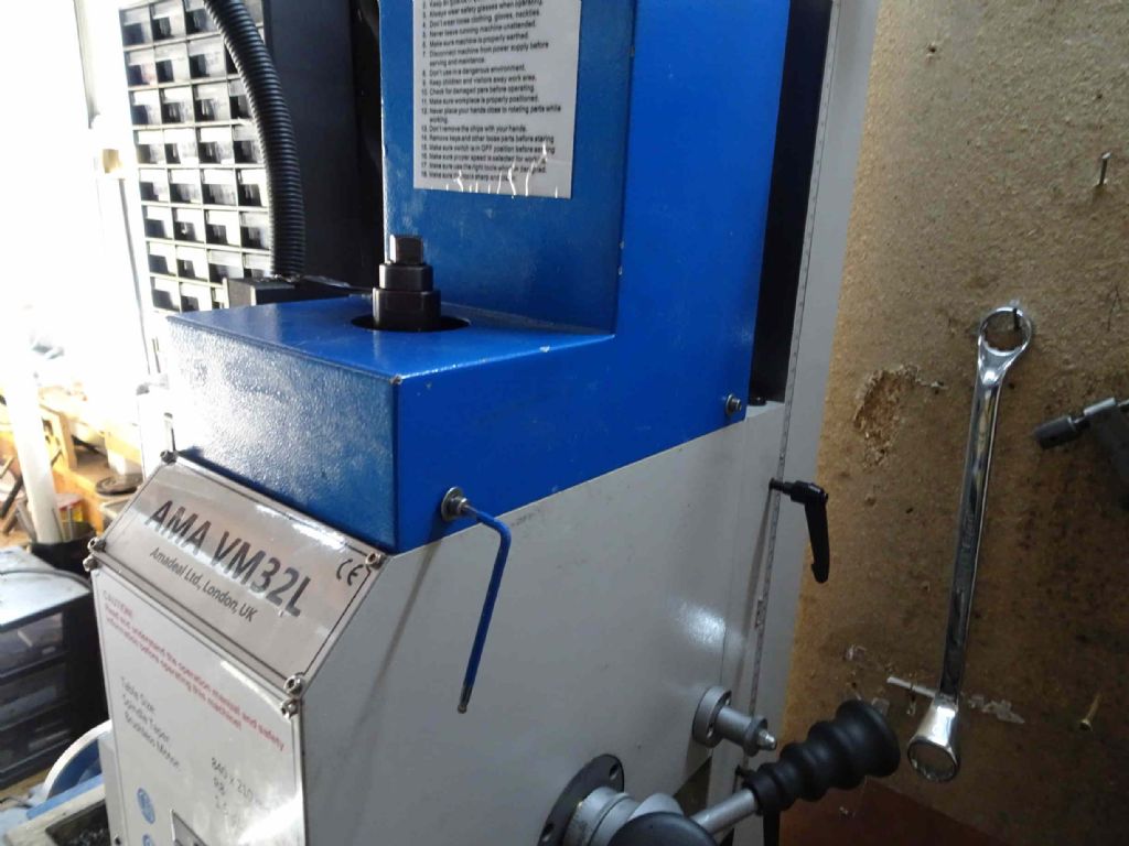
                                  First the top cover

                                  vm32l disassembly 01.jpg

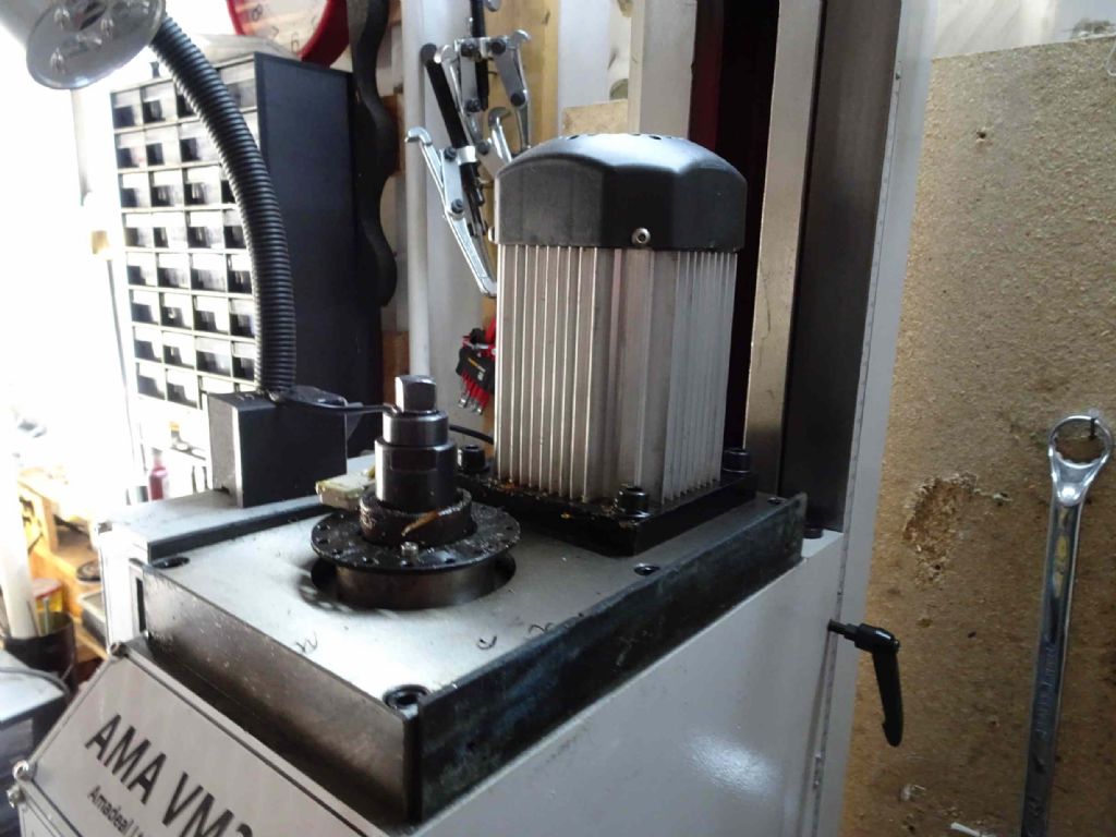
                                  Inside looks like this

                                  vm32l disassembly 02.jpg

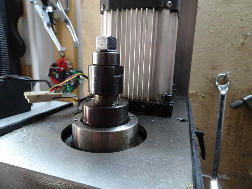
                                  Remove the drawbar and the 'retainer cup'

                                  vm32l disassembly 03.jpg

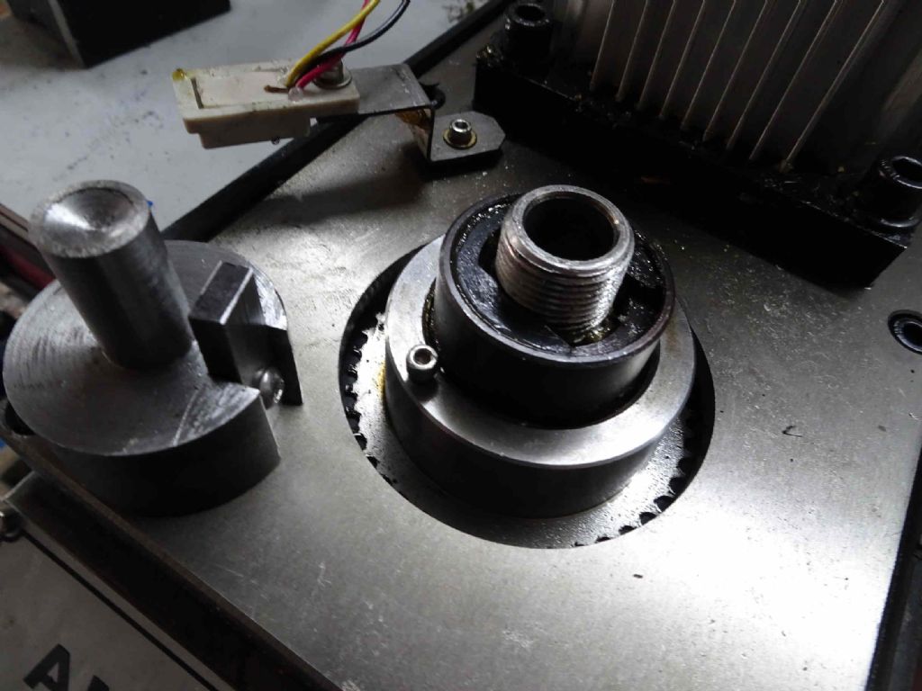
                                  Then I got stuck

                                  vm32l disassembly 04.jpg

                                  So there's a thing which looks a bit like a circlip (part 201 a 'position washer) but with the straight sides.- sorry not a particulary good picture. it will move about 10 degrees and then stops. I made the thing on the left because I thought it unscrews and needed a bit of help (I've learnt about bearings and hammers). However, it doesn

                                  ………………………………………………………………………

                                  ………………………………………………………..

                                  That was me having a thought and a quick trip out to the shed. In the diagram there's a spring under the assembly and I wondered if I could push the bush down and release the position washer that way. It turns out I can indeed push the bush down, however, I am now showered and about to embark on the barbeque (who knows when we'll get the chance again) and the wine, so not a good time to start messing with dirty machines again.

                                  I will report back tomorrow all being well.

                                  Iain

                                  #467286
                                  Iain Downs
                                  Participant
                                    @iaindowns78295

                                    I've decided to pull back from this. At least for now.

                                    Overnight I realised that my last milling test was done with the spindle unlocked, so I thought I'd try facing again with the spindle locked.

                                    So I did, and it was better – not quite the mirror surface you see above, but OK. And I realised I have no idea what metal I was cutting on. It should be EN1A, but it just came from my bits box.

                                    I then tried without the lock and it was OK. Tried different cut depths and it was OK – with and without the lock.

                                    I believe that my initial problem (the drill thing) is simply due to a bad chuck. I will, in due course either but another one or take it to bits and see if I can fix it.

                                    I will also double check the bar (thanks for the advice on that). But I decided not to take the machine apart today.

                                    Instead I spent some time on my saw table. MY welding is as bad as I thought, though after tweaking various settings on the welder (Clarke 150EN – second hand!), at least the bits of metal stayed together after 'welding'. Don't ask about the sputtering and grinding required!

                                    So I think that I will just try and use the mill for a bit. It's possible that I've got over-excited and it's really the same mill I bought.

                                    My apologies for any stress and excitement I may have caused here, though … well, there may still be something wrong!

                                    Iain

                                    #471366
                                    Graham Meek
                                    Participant
                                      @grahammeek88282

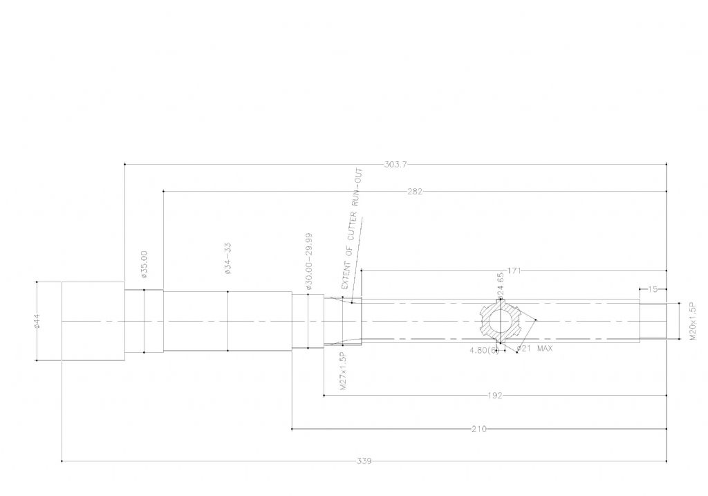
                                      cracked r8 spindle .jpg

                                      I eventually found the rough sketch I made of the defective spindle which was eventually salvaged. Just in case anyone finds themselves in a similar position and need to make a new spindle I have uploaded a rather poor Jpg drawing.

                                      If there is a requirement for a better image of this drawing then I can furnish a PDF. If there is a method to make this available to the Forum, this would save a lot of exchanges of emails. Perhaps Neil or Jason can help here?

                                      Regards

                                      Gray,

                                      #471376
                                      Neil Wyatt
                                      Moderator
                                        @neilwyatt

                                        Hi Gray,

                                        If you email me a PDF I can make it available on the forum.

                                        Thanks

                                        Neil

                                        #471457
                                        Iain Downs
                                        Participant
                                          @iaindowns78295

                                          Just an update.

                                          I clearly buggered up the original chuck and there was something I wanted to do, so I ordered a cheap one which could come quickly from Amazon.

                                          It arrived and I tried it out on with a 4.4mm drill into some mild steel (my task was drilling some holes for an M5 thread). The result was 4.6mm entry hole and 4.5 mm exit hole.

                                          That one's for the bin.

                                          However, I then did something which I'd been thinking about, which was to take my older big chuck (another 13mm) off the MT2 mandrel (which took quite a bit of welly) and set it on the R8.

                                          The result was a 4.4mm hole through the mild steel!

                                          So the long and the short is that the chuck that came with the mill was rubbish (or I managed to break it somehow) and that I need to get a decent 13mm / B16 chuck (probably from ARC) when my next budget period strikes.

                                          In passing, I see that Ketan has keyless chucks on there. Do the add any value or is it just so you spend less time looking for the chuck key?

                                          Iain

                                          #471458
                                          old mart
                                          Participant
                                            @oldmart

                                            You can get MT2 to R8 adaptors, with or without tangs if the drill chuck is also used on a lathe.

                                            #471473
                                            Iain Downs
                                            Participant
                                              @iaindowns78295

                                              HI, Old Mart.

                                              I can easily find R8 to MT2 but haven't seen one the other way round. I'd be surprised unless the R8 was basically stuck on the end of the MT2 as the R8 is thicker!

                                              I had thought of getting an R8 to MT2 so that I could use tooling from my mill and lathe, but I don't think there's a right lot which I've not got an R8 mandrel for. Some centres, but that's not a lot of use on a mill.

                                              Iain

                                              #471474
                                              John Rutzen
                                              Participant
                                                @johnrutzen76569

                                                I have an Amadeal VM25L with an R8 taper so I just went and checked it. No crack thankfully but i don't tighten the drawbar very much, just snug it up. My spindle isn't very hard at all, I can scratch the outside very easily with an ordinary steel scriber and the nut flats show some wear after 4 years use. I was a bit concerned the spindle wasn't hard enough but I'm glad now it isn't harder. There is not a lot of metal around the taper, only about 4mm. Would it be a good idea to turn up a steel ring and loctite it in place?

                                                #471490
                                                Neil Wyatt
                                                Moderator
                                                  @neilwyatt

                                                  Gray has kindly sent me the PDF of his R8 spindle drawing. To make it easier to upload I've shortened the name but it is here:

                                                  Graham Meek's Cracked R8 Spindle Drawing

                                                  Thanks Gray!

                                                  Neil

                                                  Edited By Neil Wyatt on 13/05/2020 19:02:31

                                                  #471493
                                                  Michael Gilligan
                                                  Participant
                                                    @michaelgilligan61133

                                                    Thank you both … Gray & Neil

                                                    I remain slightly bewildered however … as I was hoping to see a section showing the thin wall and any stress raisers in the defective original.

                                                    Just for ‘academic interest’

                                                    MichaelG.

                                                    #471509
                                                    John Rutzen
                                                    Participant
                                                      @johnrutzen76569

                                                      The drill chuck that came with my Amadeal mill wasn't accurate but I had a spare new [30 years ago] Jacobs chuck that I took off the MT3 arbor and fitted to a new chinese arbor I bought on eBay. That is much more accurate.

                                                    Viewing 25 posts - 26 through 50 (of 59 total)
                                                    • Please log in to reply to this topic. Registering is free and easy using the links on the menu at the top of this page.

                                                    Advert

                                                    Latest Replies

                                                    Home Forums Manual machine tools Topics

                                                    Viewing 25 topics - 1 through 25 (of 25 total)
                                                    Viewing 25 topics - 1 through 25 (of 25 total)

                                                    View full reply list.

                                                    Advert

                                                    Newsletter Sign-up