Mill spindle runout

Advert

Mill spindle runout

Home Forums Beginners questions Mill spindle runout

Viewing 25 posts - 26 through 50 (of 55 total)
  • Author
    Posts
  • #613000
    Pete Rimmer
    Participant
      @peterimmer30576

      DTI's and plunger-style dial indicators can both act as comparators and both take direct measurements.

      One of the most common mistakes made whilst taking direct measurents with a DTI is the one shown in Steve's video (sorry Steve) where the lever is not tangential (or parallel, if it's a flat surface) to the work. Steve's is a particularly good example because the lever is so far from tangential the cosine error will be large. In the video it is showing 3 thou TIR but if the DTI were moved down so the stylus was parallel to the floor that reading would probably be less than 0.002".

      Other things which can cause false readings are:

      Using the instrument held rotated in the holder so that the lever is not swinging perpendicular to the axis of the shaft being rotated. Always make sure the instument is held perpendicular to the part.

      Using the instrument with a different length stylus than it was designed to use. Fit a longer stylus, it will under-read. A shorter one will over-read.

      Plunger type dial gauges will also over-read if the stem is not perpendicular to the work, though the error is usually very small. If you're taking runout measurements as in the video it must also be reading on the centreline of the part, to again avoid cosine errors.

      Advert
      #613002
      Michael Gilligan
      Participant
        @michaelgilligan61133
        #613007
        Pete Rimmer
        Participant
          @peterimmer30576

          Yes the pear shaped stylus is designed to reduce cosine error but it won't prevent the over-reading error that Steve's setup would incur.

          #613009
          Pete Rimmer
          Participant
            @peterimmer30576

            Steve, looking at this video:

            *LINK*

            Since you are measuring directly over the vee block this should be showing no runout. Possible causes are:

            • Bearing diameter out of round
            • Burr or ding on the egde of the bearing register causing it to ride up on the vee block. You can eliminate this by putting slip gauges in the vee blocks to raise the spindle off the wider vee so it doesn't get affcted by any edge ding.
            • Bent spindle
            • Top bearing register not concentric with bottom bearing register, or it has a ding/burr.

            Another good check you could do is put the vee block under the chuck register then use your DTI to check the taper and the bearing register. If the taper runs true but the bearing register does not, one solution could be to knurl the register to raise the diameter a bit then turn or grind it back down to the bearing diameter, whilst supporting the spindle in a lathe between a 4-jaw and a fixed steady on the chuck register. It won't be perfect but it'll get your TIR down to a couple of tenths rather than a couple of thou.

            #613015
            SillyOldDuffer
            Moderator
              @sillyoldduffer
              Posted by Michael Gilligan on 11/09/2022 06:59:04:

              Bill,

              It is my belief that the distinction is entirely artificial: Both instruments are more logically classed as Indicators; unless and until they are mounted in such a way that there is a Zero reference and the ‘system’ is calibrated.

              Even then, the dial mechanism and the [likely] cosine error both serve to make them poor Gauges.

              The use for which both were originally devised was that of a Comparator

              That's my understanding too – relying on gears limits this type of instrument's suitability for taking absolute measurements. To be repeatedly accurate the gears would have to be perfectly round, with perfectly shaped and spaced teeth, running in perfect bearings, with zero backlash. Such gearboxes are difficult and expensive to make, and highly prone to error due to wear. In practice though, geared instruments make excellent indicators because they're able to show small movements with considerable sensitivity and fit-for-purpose accuracy. But they become less reliable with increasing distance. Lever indicators are 'better' because they measure a smaller range than plunge types, and thus have less opportunity to accumulate error. The shortcomings show up when several comparators are used to take the same measurement; my dial is almost certainly different to yours!

              Digital Calipers and DROs take a different approach; their accuracy depends on a 'scale' of microscopic proportions and a differential pair of encoders that detect capacitive, magnetic or optical changes. The mechanics are very simple, not prone to wear, and – although conceptually difficult – so are the electronics.

              Most micrometers are based on a precision thread. The threads aren't made on a lathe or with a die because these methods are far too coarse; instead they're ground using specialist techniques. Despite the cost and difficulty of making micrometer threads, they're much easier than accurate gear-boxes and there's not much to go wrong when they're fitted in a micrometer. However, they can't be blindly trusted because micrometer threads and anvils wear out and frames bend if the instrument is dropped. For a micrometer to be considered accurate, it either has to be new, or recently recalibrated. In my humble opinion chaps who buy elderly second-hand 'quality' micrometers aren't buying accuracy. For rough work they can be checked with slip gauges, but here again I suspect too much faith is placed in ebay bargains!

              In my workshop none of this matters much. My machines and measuring equipment all work to about ±0.02mm which is good enough for most of my purposes. I mostly work by 'fitting', whereby parts are combined by gauging and adjusting them relative to each other, not by absolute measurements. In this type of construction a certain amount of slackness is often helpful.

              Dave

              #613018
              Pete Rimmer
              Participant
                @peterimmer30576

                Dial gauges are the easiest thing in the world to check for reading accuracy. Pass a slip under the stylus or anvil, record the reading, pass another slightly different thickness slip under it. If the dial records the difference accurately the instrument is reading correct.

                #613035
                old mart
                Participant
                  @oldmart

                  The accuracy of lever type indicators is less important than their ability to detect runout. For accuracy in actual measurement, the plunger type is designed to be fixed to a dedicated stand sitting on a surface table, and easy to check using slip gauges. With the lever type, each model is designed to work wilh a compatible length arm at right angles to the workpiece. As the angle changes, small errors accumulate. That has no importance if, for instance you are adjusting round work in an independent 4 jaw chuck, the final zero needle movement is all you are aiming for.

                  An instance of a dial indicator not being accurate in measurement, but functioning perfectly well is the co-axial type indicator used in milling for centering a bore with the spindle. The numbers on the dial are meaningless as there are a number of different types and lengths of lever probes and angles set used with one instrument, which mean the movement bears very little relationship to the pointer movement. Since the object is normally to attain zero pointer movement, that doesn't matter.

                  #613036
                  martin haysom
                  Participant
                    @martinhaysom48469
                    Posted by Pete Rimmer on 11/09/2022 11:08:44:

                    Dial gauges are the easiest thing in the world to check for reading accuracy. Pass a slip under the stylus or anvil, record the reading, pass another slightly different thickness slip under it. If the dial records the difference accurately the instrument is reading correct.

                    but firstly you need to check the slips so you KNOW they are correct

                    #613038
                    Pete Rimmer
                    Participant
                      @peterimmer30576
                      Posted by martin haysom on 11/09/2022 14:52:40:

                      Posted by Pete Rimmer on 11/09/2022 11:08:44:

                      Dial gauges are the easiest thing in the world to check for reading accuracy. Pass a slip under the stylus or anvil, record the reading, pass another slightly different thickness slip under it. If the dial records the difference accurately the instrument is reading correct.

                      but firstly you need to check the slips so you KNOW they are correct

                      Slips are unlikely to be out by any measurable amount. If they are still shiny, they will very likely be good. If you really wanted to be anal then do the check twice or thrice with different sizes of slip. The chances that several slips will all be worn by a similar amount are infinitesimal.

                      #613040
                      old mart
                      Participant
                        @oldmart

                        The slip gauges at the museum would all fail testing even to workshop grade. A stack of 4 would probably be 0.0001" undersize, which is plenty good enough for our requirements. When I got the box, I had to remove a thin film of rust from most of them, with a scraper and oil, not abrasives. A new Stanley knife blade works well and won't scratch the surface if used carefully.

                        #613241
                        Bill Phinn
                        Participant
                          @billphinn90025

                          Thank you particularly to Michael, Pete and Dave for enlightening me.

                          #613249
                          not done it yet
                          Participant
                            @notdoneityet
                            Posted by Bill Phinn on 12/09/2022 17:40:02:

                            Thank you particularly to Michael, Pete and Dave for enlightening me.

                            Thanks, Bill, for enlightening you.

                            Slip gauges are likely perfectly adequate, for most of us, if they can be wrung together. Likely good enough, even when they won’t, for most applications as long as they are not actually rust stained.

                            #613281
                            Bill Phinn
                            Participant
                              @billphinn90025
                              Posted by not done it yet on 12/09/2022 18:10:50:

                              Thanks, Bill, for enlightening you.

                              Thanks for the example of a category mistake.

                              #613284
                              old mart
                              Participant
                                @oldmart

                                Our slips will never wring together, but rust is a danger as it stands proud of the surface and must be scraped gently off. The tiny pits left would be bad if they covered most of the surface, but ours are about 10%, fortunately. While I have instruments that can measure down to 1 micron, in real life, I would be content with 10 microns at best for actual work and 50 generally.

                                #613299
                                Steve355
                                Participant
                                  @steve355

                                  Gosh, a lot of posts since I last looked. I put some time into it at the weekend, including refurbing a tenths dial gauge I have to put the cosine error issue to bed. But alas, every time I measured I got different results. I will post a bunch of videos in the morning to illustrate.

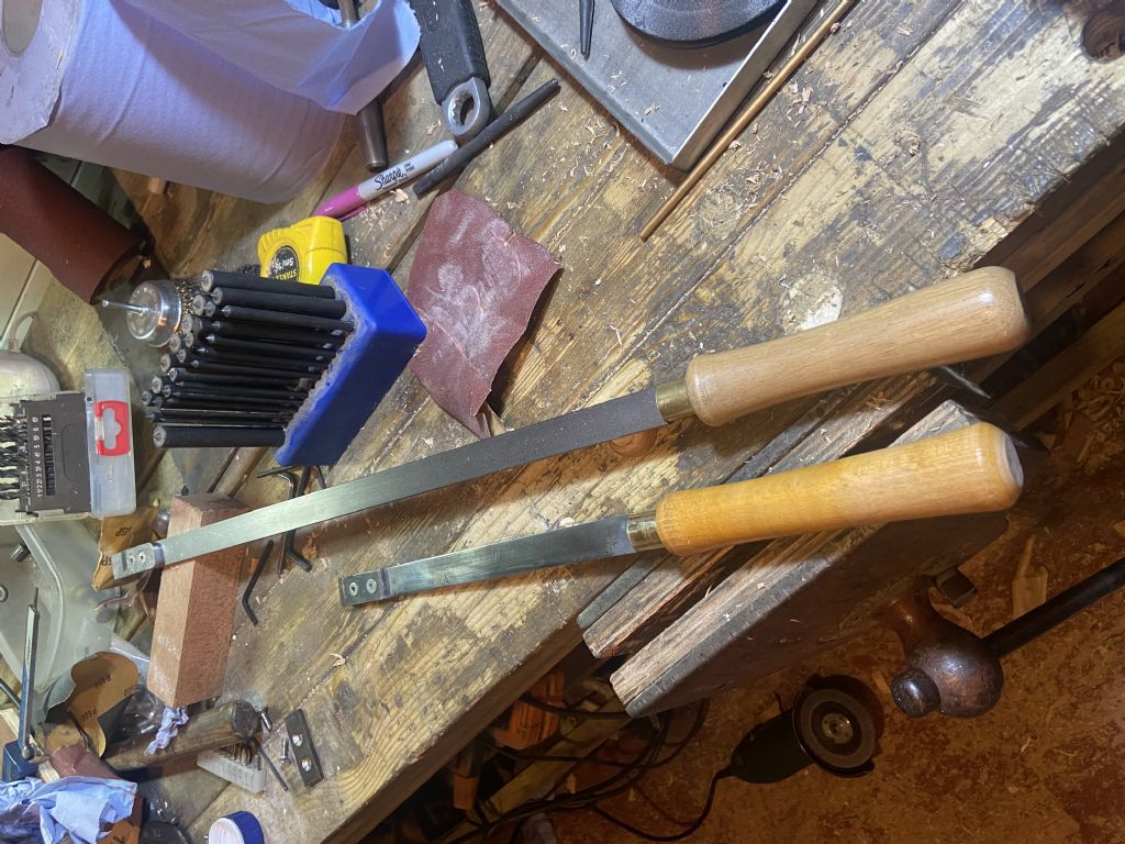
                                  after a very frustrating few hours I got fed up and decided to make myself a smaller scraper to go with the big one I bought from eBay. Big one, 60 quid. Small one, nothing.

                                  48d3afbc-5f82-4f22-9e22-b989e5d21693.jpeg

                                  #613354
                                  Steve355
                                  Participant
                                    @steve355

                                    DW Spindle Video

                                    See latest video…..

                                    Calibration of clock gauge

                                    Runout on spindle

                                    Runout on nose

                                    Runout on test bar and drill adapter

                                    Binding of spindle in bearings.

                                    So it looks like 2 problems:

                                    1) Not very well made spindle, more runout than would usually be acceptable

                                    2) Bearing issue, binding up when only finger tightness is applied to the preload nut.

                                    ”Change the bearings” everyone will say… but, is that the cause? One bearing is fairly loose and the other is very difficult to get in or out. Could the quill not be straight? The bearing seats misaligned? how could I tell? They run smoothly with no preload. New bearings = another £80!

                                    Any advice appreciated.

                                    Steve


                                    Edited By Steve355 on 13/09/2022 10:00:35

                                    #613357
                                    Graham Meek
                                    Participant
                                      @grahammeek88282
                                      Posted by Steve355 on 13/09/2022 09:59:50:

                                      Could the quill not be straight? The bearing seats misaligned? how could I tell?

                                      Any advice appreciated.

                                      Steve

                                      Edited By Steve355 on 13/09/2022 10:00:35

                                      In an earlier post I did mention how to check to see if the spindle is bent. I would check this first before I did anything else.

                                      You are half way there with your set-up above.

                                      Also if the run-out on the taper test bar is getting progressively larger away from the spindle nose then this will also point to a bent spindle, but, it will also point to a Morse taper that is not true to the spindle centre-line, i.e. at an angle.

                                      To check the quill bearing registers set one bearing inner face on a circular parallel, (Old ball bearing outer races are good for this). Using your DTI clock the exposed bearing inner face. You are only interested in the face alignment with this test.

                                      In the vee blocks rotate the quill to check for run-out of the outer bearing diameter registers. Mark any high spots on the outside of the quill with a magic marker pen.

                                      If the run-out is the same magnitude and in line then do not worry.

                                      If the run-out is 180 degrees opposite then you have a problem. It is salvage-able but only if you have the equipment.

                                      If the faces are out then it is a case for setting up in the lathe with a fixed steady and skimming the face or faces. This set-up will also allow you to bore the bearing diameter register oversize and insert a sleeve to correct the 180 degree problem.

                                      Regards

                                      Gray,

                                      #613360
                                      not done it yet
                                      Participant
                                        @notdoneityet

                                        If, as a last resort,I were to have to make a new spindle, I would machine the socket first and then machine the spindle around that. The soft blank arbors, I mentioned earlier, would be used as one centre for the workpiece.

                                        #613387
                                        peak4
                                        Participant
                                          @peak4

                                          When you have got your head around Graham Meek's advice re proving whether the spindle is bent and whether the morse taper is axially correct, but off centre, I wonder if a sensible and cost effective option, will be to change the bearings for taper rollers.
                                          I believe it was a mod sometimes done using Timken Timken 15578/15520 TS Single-Row Taper Roller Bearing 1×2.25×0.6875 inch. This wouldn't directly help you, as everything would still run off-centre.
                                          If you have a look through the various catalogues and websites, such as this one you should be able to find one with the correct OD, and a larger ID, say 1.0826"/1.125" x 2.25"
                                          https://simplybearings.co.uk/shop/Taper-Roller-Bearings-Taper-Roller-Bearings/c1_5459/index.html?selection=Tapered+Roller+Bearings+Cup+and+Cone+Assemblies

                                          You could then sleeve the bearing surfaces on the centre spindle, and run it between centres.
                                          This would allow you to re-machine where the bearings sit, and thus have them concentric with the morse taper and Myford chuck register.

                                          I have lots of documentation, recovered from the old Dore Westbury Yahoo group before its demise.
                                          PM me your full contact details, and I can burn it to a CD/DVD, or maybe zip it up into a large file for one of the free file transfer services.
                                          I'll not reproduce it here for copyright reasons.

                                          p.s. an alternative way of seeing what's not concentric might be to use your lathe.
                                          If it has a Morse headstock, get an MT2 blank arbor, fit directly in the headstock taper, via a size adaptor sleeve if need be.
                                          Take a light skim off the outer stub, to make sure that it is concentric and axial.
                                          Hold this newly finishes stub in your independent 4 jaw, and dial it in with your tenths clock.

                                          You now have an MT2 taper, on which to sit your DW inner spindle. Your clock can now sit on the cross slide/saddle and move up and down the DW spindle to give you an idea what's happening.

                                          This arrangement could also be used for re-machining the aforementioned sleeves, and might even allow a slight correction if the female taper is very slightly off axially.

                                          Bill

                                          Edited By peak4 on 13/09/2022 13:40:10

                                          #613390
                                          Tony Pratt 1
                                          Participant
                                            @tonypratt1

                                            Following on Graham's observations, when I made my DW mill back in the 1970's I rejected the first part machined spindle as the Morse taper was not in line with the part and rear centre axis so if I had carried on and ignored this issue when I applied the tail stock centre to support the part it would have flexed said part and created in effect a bent spindle when machined. they were surprised I picked up this fault but precision engineering is my profession so these things get noticed, the spindle was replaced with a correct part and I suppose some one else got the faulty one?

                                            Tony

                                            #613398
                                            old mart
                                            Participant
                                              @oldmart

                                              To make sure that any error is in the spindle and not the MT arbor fitted would be to mark the spindle and tool and then refit the tool at 180 degrees to its original position. If the error is the same, it is the spindle and if it changes, the tool is suspect.

                                              I have a couple of test bars,one about 7" long and the other 12" with MT2 ends and centres, bought for the lathe. They are both more accurate than my measuring equipment. Very useful also for testing Morse tapers, but care must be taken freeing them from the taper for fear of damaging the centre at the end.

                                              Edited By old mart on 13/09/2022 14:28:32

                                              #613416
                                              John P
                                              Participant
                                                @johnp77052

                                                Hi Steve

                                                Looking at your latest video it is clear that the bearing seats
                                                on the shaft are not round.
                                                Just watch this video here it may be of some use

                                                Some of the suggestions on this thread have not taken into account
                                                this in your opening posting,
                                                ———–
                                                "The spindle doesn’t have a very good finish (home made obviously). But I’m
                                                not in a position to remake it as it’s too long for my lathe."
                                                ——————-
                                                With that in mind it would seem pointless to even try to re-machine
                                                this spindle.
                                                ———–
                                                This part of Tony Pratt's posting struck a chord with me

                                                "when I made my DW mill back in the 1970's I rejected the first part machined
                                                spindle as the Morse taper was not in line with the part and rear centre axis so
                                                if I had carried on and ignored this issue when I applied the tail stock centre
                                                to support the part it would have flexed said part and created in effect a bent
                                                spindle when machined."
                                                ————————–
                                                I think that you have to go back to the way the Dore westbury kit of parts
                                                were supplied, Most of the major parts of the machine are already made and
                                                finished to complete the machine some additional work mostly drilling
                                                and tapping holes for assembly .
                                                Some parts like the Quill and spindle are only part made ,my own spindle
                                                supplied as a piece of bar stock with through hole for the draw bar
                                                and pre-machined 2 morse taper and centered 2 morse taper plug ,it was
                                                obvious from the start that the through hole about 15 inch in length had been
                                                drilled from each end as the junction could be easily seen by looking through.
                                                Being a complete beginner at this then, i did not fully realize the significance that
                                                this would have and as you may guess the taper runs out in an axial direction.
                                                Nearly 40 years on correcting this would be a simple job.

                                                Your shaft seems to have many errors so much so it would be easier to
                                                remake the shaft ,as you have a lathe that is too small you could consider
                                                just making the lower part and the spline upper part as two parts and
                                                using loctite to join them together. I think the biggest problem you may face
                                                is first drilling a through hole through a piece of barstock of about 7 1/2 inches
                                                on a lathe that is only 12 1/2" between centres, if you could manage to do that
                                                and set up each end of the through hole and turn the centre seating, this
                                                cutting from an old book shows how the rest could be done using a sprung
                                                dog centre and fixed steady.


                                                John


                                                sprung centre  dog .jpg

                                                Edited By John P on 13/09/2022 17:06:49

                                                #613430
                                                Graham Meek
                                                Participant
                                                  @grahammeek88282

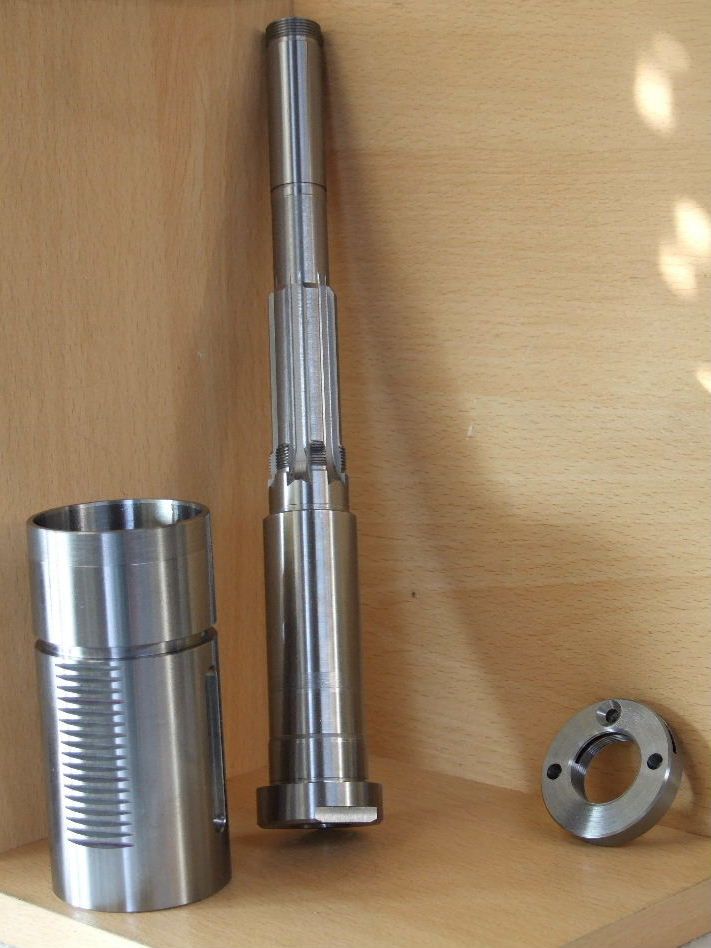
                                                  As regards making a new spindle the socket would be the last thing to do in my book. There is always a very good chance with the amount of material being removed that the new spindle will distort due to the locked up stresses in the bar stock. Far better to rough out and finish machine such an item.

                                                  This is how I made the spindle below,

                                                  new parts for redesigned fb2 quill.jpg

                                                  Regards

                                                  Gray,

                                                  #613432
                                                  Michael Gilligan
                                                  Participant
                                                    @michaelgilligan61133
                                                    Posted by John P on 13/09/2022 17:06:02:

                                                    Hi Steve

                                                    […]

                                                    .

                                                    Nice to see the material specification in that post of your, John

                                                    “crucible steel spindle forging” … those were the days !!

                                                    MichaelG.

                                                    #613446
                                                    John P
                                                    Participant
                                                      @johnp77052

                                                      Posted by Michael Gilligan 13/09/2022 20:08:05

                                                      Nice to see the material specification in that post of your, John

                                                      “crucible steel spindle forging” … those were the days !!

                                                      MichaelG.
                                                      ————————————————–
                                                      Hi Michael,

                                                      Was from a re-print of an original book that was published
                                                      in 1920's useful method for the OP as his lathe is short on
                                                      centre distance.

                                                      Later on a similar illustration for finishing still using
                                                      the same setup sprung type centre and fixed steady which
                                                      is useful for finishing if you have such a thing.grinding internal taper.jpg

                                                    Viewing 25 posts - 26 through 50 (of 55 total)
                                                    • Please log in to reply to this topic. Registering is free and easy using the links on the menu at the top of this page.

                                                    Advert

                                                    Latest Replies

                                                    Home Forums Beginners questions Topics

                                                    Viewing 25 topics - 1 through 25 (of 25 total)
                                                    Viewing 25 topics - 1 through 25 (of 25 total)

                                                    View full reply list.

                                                    Advert

                                                    Newsletter Sign-up