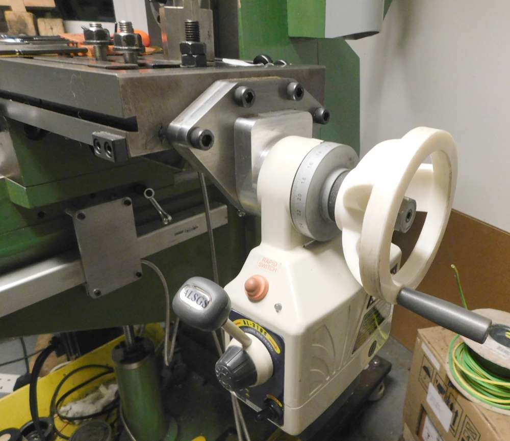
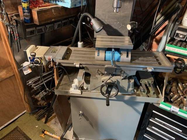
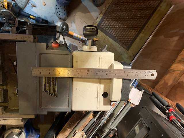
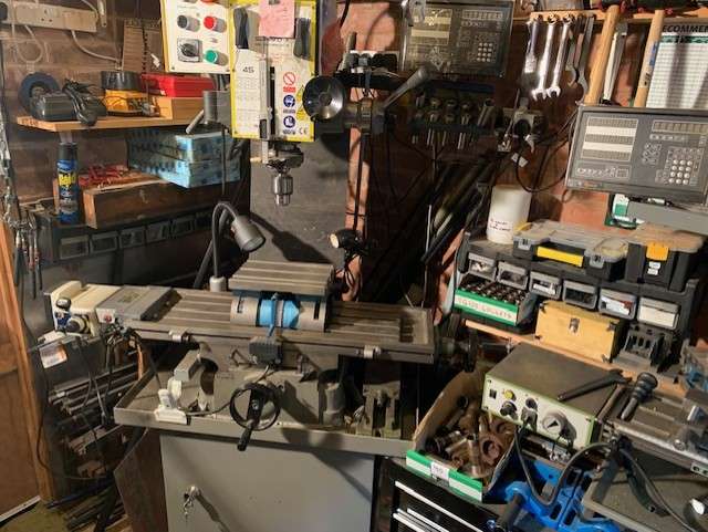
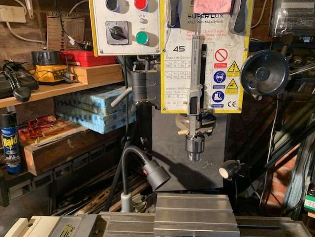
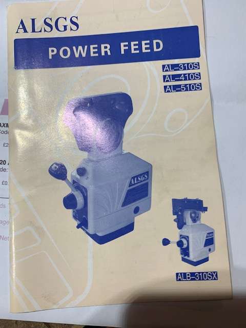
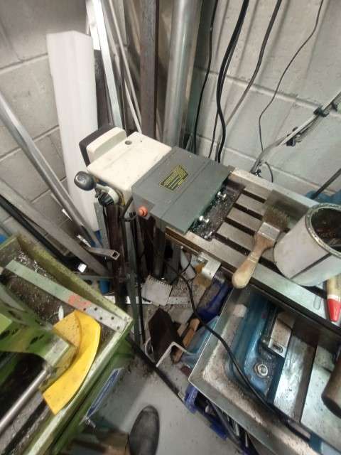
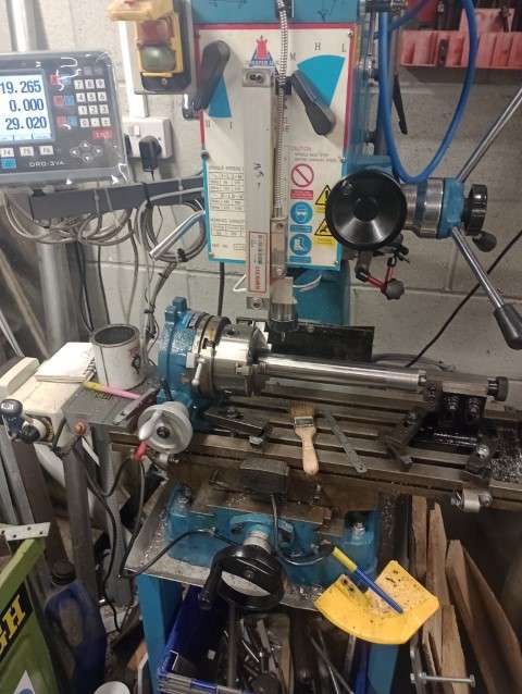
Mill Power feed unit.
Mill Power feed unit.
- This topic has 57 replies, 21 voices, and was last updated 13 January 2025 at 15:47 by
 old mart.

- Please log in to reply to this topic. Registering is free and easy using the links on the menu at the top of this page.
Latest Replies
-
- Topic
- Voices
- Last Post
-
-
Old plastic handled screwdrivers
Started by:
Dave Halford
in: Workshop Tools and Tooling
- 9
-
8 July 2025 at 18:04
John Purdy
-
Easiest/cheapest source of R8 socket
Started by:
Beardy Mike
in: Workshop Tools and Tooling
- 1
-
8 July 2025 at 18:03
Beardy Mike
-
Transwave converter – plugged in motor, tripped RCD
Started by:
ell81
in: Beginners questions
- 1
-
8 July 2025 at 17:58
ell81
-
in line oil check valve
Started by:
Garry Coles
in: General Questions
- 4
-
8 July 2025 at 17:32
Speedy Builder5
-
Angle grinder woes
Started by:
Speedy Builder5
in: Workshop Tools and Tooling
- 5
-
8 July 2025 at 17:25
Speedy Builder5
-
motor and switch wiring Myford ML7
Started by:
1957jmh
in: Workshop Tools and Tooling
- 2
-
8 July 2025 at 17:08
noel shelley
-
Square end on round stock – Milling?
Started by:
Roger TheShrubber
in: Workshop Tools and Tooling
- 15
-
8 July 2025 at 16:55
old mart
-
File backup to external hard drive, incremental etc?
Started by:
Peter Bell
in: The Tea Room
- 8
-
8 July 2025 at 16:53
Peter Bell
-
Chester Champion, warco ZX15 drawbar
Started by:
martian
in: Manual machine tools
- 4
-
8 July 2025 at 16:49
martian
-
Bridgeport ways and wear
Started by:
inline
in: Manual machine tools
- 6
-
8 July 2025 at 15:44
duncan webster 1
-
Drilling holes in blades?
Started by:
Bo’sun
in: The Tea Room
- 8
-
8 July 2025 at 15:28
Bazyle
-
Need help choosing a lathe chuck
1
2
Started by:
th1980
in: Workshop Tools and Tooling
- 21
-
8 July 2025 at 13:30
JasonB
-
Bosch PBD 40 bearing upgrade
Started by:
th1980
in: Manual machine tools
- 4
-
8 July 2025 at 13:16
th1980
-
After all these years … I fell for a scam :(
Started by:
Michael Gilligan
in: The Tea Room
- 4
-
8 July 2025 at 12:58
Robert Atkinson 2
-
Boiler Design – issue 4765
1
2
…
7
8
Started by:
Charles Lamont
in: Model Engineer & Workshop
- 26
-
8 July 2025 at 11:00
Nigel Graham 2
-
Starrett and other tool manufacturer wood boxes
Started by:
Ian Owen NZ
in: Workshop Tools and Tooling
- 12
-
8 July 2025 at 10:28
Ian Owen NZ
-
How many spokes do I really need?
Started by:
Fulmen
in: Related Hobbies including Vehicle Restoration
- 6
-
8 July 2025 at 08:27
Fulmen
-
Hi, new member from Liphook,Hants
Started by:
Chris Rushton
in: Introduce Yourself – New members start here!
- 1
-
8 July 2025 at 04:01
Chris Rushton
-
A grasshopper of unknown vintage
Started by:
mikemunson
in: Stationary engines
- 4
-
7 July 2025 at 23:43
Nigel Graham 2
-
Maisie lubricator
Started by:
ferroequinologist
in: Locomotives
- 8
-
7 July 2025 at 23:23
Nigel Graham 2
-
Herbert B drill – a question and a curiosity…
Started by:
gerry madden
in: Manual machine tools
- 4
-
7 July 2025 at 21:15
gerry madden
-
Bridgeport Series 1, table power feed.
Started by:
Daedalus
in: Manual machine tools
- 1
-
7 July 2025 at 21:04
Daedalus
-
road registration and traction trailer.
Started by:
RRMBK
in: Traction engines
- 8
-
7 July 2025 at 19:36
here again
-
Twin Engineering’s heavy mill/drill quill removal
1
2
Started by:
Martin of Wick
in: Manual machine tools
- 11
-
7 July 2025 at 17:18
Nicholas Farr
-
A Persistent Scam
Started by:
Chris Crew
in: The Tea Room
- 7
-
7 July 2025 at 17:05
Trevor Gale
-
Old plastic handled screwdrivers
Latest Issue

Newsletter Sign-up
Latest Replies
- Old plastic handled screwdrivers
- Easiest/cheapest source of R8 socket
- Transwave converter – plugged in motor, tripped RCD
- in line oil check valve
- Angle grinder woes
- motor and switch wiring Myford ML7
- Square end on round stock – Milling?
- File backup to external hard drive, incremental etc?
- Chester Champion, warco ZX15 drawbar
- Bridgeport ways and wear

