Re Terry D `s post today @ 0345. Could it be that back in 1955 and earlier, Metric threaded bolts were made from Imperial sized Hex. bar as this was probably all that was cheaply available but since industry has gone over to Metric, metric sized Hex. bar is now the el cheapo stuff to use, even for Imperial/USA threaded bolts?
For sometime now, it has been necessary to use Metric spanners on certain BA sized Hex. Hd. screws, as Metric Hex bar is all thats available.
Lots of interesting stuff here. A couple of observations:
I use Tubal Cain’s drill sizes as a starting point but sometimes go one, or for larger threads two, sizes smaller as sometimes the amount of thread looks really shallow using his sizes (ebven with new drills). These sizes ARE much kinder on taps but beginners really should remember to use cutting oil on the tap as well.
I had an interesting one the other day – 12 BA machine screw and standard nut overtightened – the head of the screw sheared off and I was tightening from the nut side i.e. the thread engagement in the nut was strong enough to more or less pull the head off the screw!
I contemplated this and realised that the core area is less than the cross section of the full length of engaged thread, and that as long as the threads can deform slightly under load the whole length will share the load.
Neil
Now the real question – should the lock nut go on top or underneath?
Being ex-aircraft industry myself it is either lock wired or castellated nut and split pin as far as I am concerned, why fit two nuts when you can fit one, you have to think of the weight may be that’s why the beam engine as a source of power for flying did not catch on, too much weight due to all those locknuts.
snip
Rob
I suppose it depends on the application. In my experience in industrial vibrating screens and conveyors, locking wire or castellated nut and split pins, just snap. I was always under the impression that these methods were used to retain nuts/set screws in their locations, should they become loose for some reason or other, e.g. you do not want a loose set screw working its way out of a hole inside a gearbox and getting mangled up with the gear teeth. Nylocs seldom vibrate loose in my experience.
Hi all, further to the question about tapping drill sizes, below is a couple of quotes from a Presto Engineers Cutting Tools booklet.
Tap Drill Size
“Use the correct tap drill size, ensure that the hole is round and true. Those tap drill sizes given in pages 23 t0 27 generally afford a thread depth o 75% or more – which we recommend for short hole tapping. For long thread lengths, fine pitches and small diameters a reduced amount of thread depth is sometimes desirable.”
Hand Taps
“For hand tapping, the conventional set of 3 taps with straight flutes is recommended. It is essential that the tap is presented squarely to the work and that the taps are correctly aligned. When these taps are used in a machine it is not usually necessary to use the taper tap.”
Nowhere in this booklet do they give different tapping drill sizes for machine or hand tapping. The tables fall within the max/min minor dia’s of the respective nut standards Metric BS3643; Unified BS1580; Whitworth BS84; BA BS3643
The sizes given in pages 23 -27 for the Metric taps are the same as those in the Zues booklet and other booklets that I have and I have never had any real problem with them and will continue to use them in general terms, but please note that I’m not trying to convince others not to use Tubal Cain’s references or any any one else’s ideas for that matter. You must draw you own conclusions from the information above.
There’s no right or wrong figure that must be obeyed. The point was simply that for a neglible loss of thread engagement, there is a huge reduction in the risk of breaking the tap. Tubal Cain argues that in the vast majority of cases likely to be encountered by the model engineer, the benefits of driling a few points larger massively outweigh the disadvantages. It could be argued that 80% engagement is even better but even the Zeus tables draw a line. It’s just a question of where the builder wants to draw it. The figures TC uses to illustrate the principles and prove the maths are based on the specs of what metric nuts and bolts should be and as mentioned earlier on, allows for a slight increase in bearing surface due to extrusion effect. As with all these things, the builder should work with whatever figures they feel comfortable about given the materials and quality of tools they have to work with.
For the record, here is a direct quote by TC from “The Model Engineer’s Handbook” :
“The majority of published tapping drill tables are intended for use with tapping machines or adaptors. These have slipping clutches and/or automatic reversal to cope with overload or bottoming of the tap. The tables are designed to accept the higher thread engagement found in ‘production’ workshops and are not suitable for hand tapping.”
From the same page:
“The other type of failure – shear across the thread, or stripping – is unaffected by any reduction of thread engagement until at least 50% of the thread has been removed; even then the screw would still be stronger in shear than in tension.”
I note that the pictures of a stripped thread show that teh thread has parted with the stock at or near the root of the thread- Tubal Cain was right, as iif it breaks off at the root, thread depth is irrelevant.
Neil
P.S. Locknut on top – Tubal Cain demonstrated why this is right, why many tutors were wrong and generations of peple actually fitting the things were right. But I ain’t digging out the reference tonight!
Neil, I’ll save yer t’ trouble. The article is entitled ‘Bolts, Nuts & Screws’ and appeared in ME volume 140, number 3500, page 1069, 1st November 1974. How’s that for memory!
Oh, alright, it just happened to be open on my desk, as I was reading the article last week following on from a discussion on locknuts on the TractionTalk forum.
OK , Andrew proberbly knows about Pal nuts, they are proberbly still in use as lock nuts on the cylinder base nuts on Continental engines, and I think Lycoming too, there must have been some particular reason why these nuts were used, my thought is that they ensure that the nut locks the full nut, and does nt take the load as an over tightened lock nut can.
I was looking at the subject the other night, length of thread/ thickness of nuts was being discussed, it has been found that 1/3 of the load is taken on the first thread, then in deminishing amounts through the nut. Ian S C
Ian, yes I do know what Palnuts are; ! couldn’t look on the Lycoming in the Pawnee this morning to check as flying was cancelled. Too windy! Palnuts were definitely used on VW conversions to aero engines. Rumour has it that the flat four VW engine was originally designed as an aero engine.
It would seem that Palnuts are better able to resist cyclic loading than conventional locknuts. I don’t why; may be they are a little more flexible?
Hi, this may interest some of you, but may make some of you cringe, by some of the posts in this thread.
Today a colleague and myself were somewhere in England away from civilization, fitting an access assembly to a structure, which was made in our workshop. Two components of the assembly were to be bolted on with four 12mm nuts and bolts each, however, because of the way the scaffolding was erected, it was not possible to reach the other side of the holes that we had to drill for the bolts, to put on the washers and nuts. We were around 50 miles away from the workshop and the job had to reach the first stage today, so the only way was to drill and tap the holes.
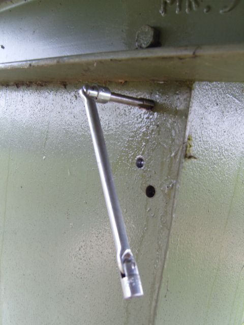
We had not intended to do any tapping of any nature, so the gear was not loaded on the van, therefore we had to look in our tool boxes to see what we could find. Between us we found a 10.2mm twist drill, a 12mm plug tap and a double ended swivel car brake adjusting spanner, which one end fitted the square of the tap. (I had a tap, wrench but it couldn't be swung in the position where the holes are)
I therefore proceeded to drill and tap all 8 holes which were needed, which have a depth of 25mm with the gear we had with total success, without breaking even one of the cutting teeth or tap and all the bolts fitted in without any straining what so ever. (Didn't break my wrists either)