metric drawings imperial workshop

Advert

metric drawings imperial workshop

Home Forums CAD – Technical drawing & design metric drawings imperial workshop

Viewing 25 posts - 1 through 25 (of 28 total)
  • Author
    Posts
  • #167305
    Martin Botting 2
    Participant
      @martinbotting2

      Forum posters,

      I have a project on the bench in it's infancy i.e. in my head. I have got some drawings that are annotated in german and my knowledge of that is as good as my knowledge of rocket science I would like to ask for some pointers from the brains trust would it be wise/ fool hardy, or downright brain damage if I convert the dimensions using a conversion app into Thou and attempt to machine to that. I would not like to think that the conversion of my lathe and mill to imperial lead screws and dials etc would cost so some recommendations please.

      Many thanks.

      Advert
      #21172
      Martin Botting 2
      Participant
        @martinbotting2
        #167308
        IanT
        Participant
          @iant

          Hi Martin,

          I don't think that you would have any problems at all.

          Most of my machines are 'Imperial' but I use quite a mix of imperial & metric tooling (increasingly metric – because it's cheaper here in UK). I tend to move between the two systems according to what I'm working on. If I'm working on an older machine – I'm thinking 'fractional' generally (Whit nuts & bolts etc), if I'm working on a 'published' 2.5" engine design it will probably be imperial (and I'm into thous & BA threads) but any new tooling or designs I make/design are in metric (mm) because its generally cheaper to use metric materials, fittings, taps/dies etc. these days.

          I've been working on drawings for my Sentinel (that I've mentioned elsewhere – seeking a GA) this evening and I prefer to start with a full sized drawing (where 1ft = 12" ) and then scale it down to G3 (1:22.6). Once scaled (it's still in inches) I then convert the drawing to metric (mm). It's very easy to move between the two systems when you have a CAD system – or even a calculator !.

          In the workshop, it's still pretty simple. I know that 1mm = 40 thou (well near enough for my purposes) – so even I can do most of the required math in my head. Working out that 0.5mm = 20thou or that 0.2mm = 8thou is really not that hard once you start doing it routinely…

          So my advice is convert your drawing directly into whatever system you prefer (or need to use) BUT if it specifies (say) metric fixings – then use them. Don't try going to "near equivalents" – use the material stated but convert the 'machined' sizes to suit yourself and/or your machines

          Hope this makes sense…it's getting late – so time for bed.

          Regards,

          IanT

          #167312
          IanT
          Participant
            @iant

            PS I'm also struggling with my technical German Martin.

            A while ago I discovered the web site of a very talented German marine modeller, Jurgen Eichart and spent some time reading his website via Bing Translate. I was interested enough in his techniques to buy his two 'milling' books from Amazon UK. { Fräsen für Modellbauer (Volumes 1 & 2) by Jürgen Eichardt } . Very useful for any small scale modeller…he states his methods for machining small items are a viable alternative to etching for instance…

            Unfortunately – it's not quite so easy to translate a book (as it is a web-page) so I'm having to work on my German. Anyone who wants a peek at his work should start here:

            **LINK**

            Regards,

            IanT

            #167313
            Ady1
            Participant
              @ady1

              Fit a DRO? Then Imp/Metric can be used at the push of a button

              #167318
              Bill Pudney
              Participant
                @billpudney37759

                Funnily enough I have a similar problem, but the other way round.

                Although I am "bilingual" in Imperial and metric, I much prefer the latter. To the extent that my machines and measuring stuff is all metric, apart from a bore mic, because I couldn't find a metric one that I could afford!. Even though I grew up with Imp. I find all the silly fractions, 3 places of decimal when clearly one place is sufficient, number drills, letter drills etc etc such a waste of time and so irritating, that now I would rather "metricate" all imperial drawings. Not trying to start any sort of upset here but it's the way I look at stuff.

                The way I do it, is to simply go over all dimensions and convert them to millimetres, mark up the drawing, neatly in red. Each dimension has to be assessed for the requirement for accuracy of course, but as I used to be a draftsman this is no problem. Drawing notes in a foreign language can be a problem. Frequently internet translators are not a lot of help because drawing notes can be somewhat cryptic. This is where forums like this can be of help.

                Best of luck!!

                cheers

                Bill

                #167320
                Stephen Benson
                Participant
                  @stephenbenson75261

                  This is something I do all the time just remember 0.040 = 1mm and 4 thou = 0.10mm and use a metric micrometer.,my mill and Cowells lathe are metric but my larger South Bend lathe is imperial

                  #167321
                  JasonB
                  Moderator
                    @jasonb

                    Although the app will do a direct conversion you will need to tweal sizes to suit nominal tooling and materials

                    eg a 6mm hole is easy enough to drill or ream to take a piece of 6mm bar but do you want to try and bore a hole 0.236" and turn down a length of 1/4 rod to 0.236"

                    As mentioned same with fixings trying to find one that is 0.118" dia is daft, either up it to say 5BA or stay with M3

                    Easiest way on the lathe is to zero your callipers/mic, open up to the metric size then zero, change to imperial reading and you know how much to take off in thou to get the finished size.

                    J

                    #167323
                    David Jupp
                    Participant
                      @davidjupp51506

                      Not directly imperial/metric, but I thought it worth mentioning that German (indeed most continental) technical drawings are likely to use 1st angle projection.

                      Depending upon which convention you are used to this could introduce an element of confusion.

                      #167325
                      Martin Kyte
                      Participant
                        @martinkyte99762

                        Personally I would leave all drawing packages in the units they were drawn in. I say this for 2 reasons. Firstly it's a lot of work to redraw everything and secondly you are far more likely to introduce either errors and or confusion if you do direct conversions because of the proliferation of decimal places. Really if you wanted to end up with an imperial drawing from a metric design you should redesign using appropriate preferred imperial dimensions. This however is even more of an ask.

                        I just do my conversions on the fly when needed. Digital calipers and mics go backwards and forwards between the two systems at the touch of a button. The main bug bear would probably be co-ordinate drilling for holes on the mill but then I have axis readouts which do this for me anyhow.

                        Regards Martin

                        #167327
                        Paul Lousick
                        Participant
                          @paullousick59116

                          A factor which you should also consider is the availability of materials and tooling. The engine which I am building was originally drawn in imperial units but the materials which are available now have changed and some are not available. Therefore I have re-designed the drawings so I can use metric materials. My mill is metric and my lathe is imperial. As most of my tooling is metric, I decided to build a metric version of the original engine.

                          I used to work for a German company, and as David has said, most of their drawings are drawn in 1st angle projection. Another reason to re-draw the original design.

                          #167429
                          Martin Botting 2
                          Participant
                            @martinbotting2

                            Dear all.

                            Thank you for your help I knew I could count on many heads to solve this problem. I have recently invested in digital callipers and mic so will try the push button cure first. Zero the calliper or mic and then switch between mm and imp…the fixtures will be metric as per drawing and the division work needed is bi-lingual.

                            The project is in fact a model marine one a voith propulsion unit the builder of the prototype propellors have produced some model drawing which I think is very good of them in these days of industrial secrets its nice that a big company like Voith have gone to the trouble of making up drawings for us miniature makers. Mr Ashley Best in his recent articles stated that his fantastic trams were not model engineering but merely models I disagree his work is engineering in the truest sense but just on a small scale.

                            If any other marine modellers or come to that engineers fancy having a go at this interesting mode of propulsion here is the link:

                            http://observethebanana.com/wp-content/uploads/2008/06/modelvsp.pdf

                            From personal experience these units in a 12" – 1 foot version are incredible to use you can literally make a boat dance.

                            thanks to everyone that posted a reply I might be bold and do a blog on the build as its a bit outside what I have done in the past, it will be a challenge. And like my usual method I am sure I will built at least 4, one that works and the other 3 in the scrap pile.

                            #167431
                            Martin Botting 2
                            Participant
                              @martinbotting2

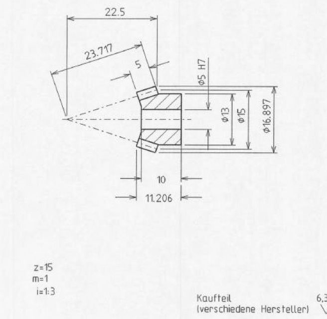
                              while I have my question head on would some kind person give me some help with this part of the project. its the drive gear (bevel gear) the annotation to the left i am presuming is the number of teeth? the module type and the ratio with its mate of 3 to 1.screen shot 2014-10-22 at 23.23.36 copy.jpg

                              #167438
                              Ady1
                              Participant
                                @ady1

                                Is that drawing meant to make sense?

                                First we have 16.897

                                Then 15?

                                Then 13?

                                followed by 5 H7

                                No wonder they lost the bloody war

                                Edited By Ady1 on 23/10/2014 00:45:10

                                #167442
                                Bill Pudney
                                Participant
                                  @billpudney37759

                                  My reading of that would be

                                  16.897 = in mm the theoretical max. diameter (actual diameter if the number of teeth was even)

                                  15 = in mm the PCD

                                  13 = in mm the diameter of the boss

                                  5H7 = in mm, the basic diameter of the bore is 5.0mm, the H7 is the tolerance +0.012/0.00mm

                                  Hope this helps clear your confusion, it's really simple actually

                                  cheers

                                  Bill

                                  Edited By Bill Pudney on 23/10/2014 01:46:54

                                  #167446
                                  JasonB
                                  Moderator
                                    @jasonb

                                    Bottom left

                                    Z = Number of teeth

                                    M = MOD1 (size of gear form)

                                    i = ratio 1:3 so mating gear likely to have z = 45 on it or 45 teeth

                                    Edited By JasonB on 23/10/2014 07:33:53

                                    #167450
                                    Martin Botting 2
                                    Participant
                                      @martinbotting2

                                      Thanks Bill and Jason I looked at the mating gear and that drawing has the same annotation but with the numbers 45 so problem is sol-ved.

                                      I am now reaching for the S H Muffet catalog to see if they have such items or bracing myself for the horrors of making them!

                                      #167462
                                      speelwerk
                                      Participant
                                        @speelwerk

                                        It also states that it is a "kaufteil" from "verschiedene Hersteller", so you should be able to buy it from several suppliers, such as http://www.maedler.nl/Article/36057600. Niko.

                                        #167484
                                        JasonB
                                        Moderator
                                          @jasonb

                                          HPC have them but make sure you are sitting down before clicking here

                                          #167489
                                          Keith Long
                                          Participant
                                            @keithlong89920

                                            Martin – as well as the EN8 steel bevels that Jason has linked to above, HPC also do the bevels that you are after in Delrin link at much better prices £20 + vat for the pair. EN8 is somewhat overkill in your application, the drawing suggests brass (CuZn) in the materials spec with mild steel as an alternative. Given the application and likely speed that you'd be using I'd think that the Delrin gears would be adequate. If they broke down eventually then they have the advantage of being standard parts that could be replaced or up graded quite easily.

                                            Brass bevel sets in 3:1 ratio used to be very common as they were used in the final drive for slot cars, but I don't know what module or dp they were. They were also fairly cheap from memory, they might still be around, a bit of "Googling" could bring them to light. Could also be worth asking at your local model shop to see if any of the RC helicopters, cars or trucks use a suitable gear set. If so they are very probably available as fairly cost efective spare parts.

                                            Just found moulded delrin bevels for your application at Motionco price even better – cheap enough to buy on an experimental basis

                                            Edited By Keith Long on 23/10/2014 14:55:50

                                            #167493
                                            JasonB
                                            Moderator
                                              @jasonb

                                              Just had a look through teh PDF, quite an interesting project and a novel method of propulsion, have I got it right that as the blade rotates the pitch varies and that is what gives the directional thrust?

                                              #167494
                                              Martin Botting 2
                                              Participant
                                                @martinbotting2
                                                Posted by Keith Long on 23/10/2014 14:45:01:

                                                Martin – as well as the EN8 steel bevels that Jason has linked to above, HPC also do the bevels that you are after in Delrin link at much better prices £20 + vat for the pair. EN8 is somewhat overkill in your application, the drawing suggests brass (CuZn) in the materials spec with mild steel as an alternative. Given the application and likely speed that you'd be using I'd think that the Delrin gears would be adequate. If they broke down eventually then they have the advantage of being standard parts that could be replaced or up graded quite easily.

                                                Brass bevel sets in 3:1 ratio used to be very common as they were used in the final drive for slot cars, but I don't know what module or dp they were. They were also fairly cheap from memory, they might still be around, a bit of "Googling" could bring them to light. Could also be worth asking at your local model shop to see if any of the RC helicopters, cars or trucks use a suitable gear set. If so they are very probably available as fairly cost efective spare parts.

                                                Just found moulded delrin bevels for your application at Motionco price even better – cheap enough to buy on an experimental basis

                                                Edited By Keith Long on 23/10/2014 14:55:50

                                                Thanks Keith for the leg work and again thanks to everyone for posting replies! I owe you all a cyber cuppa tea in the ether based canteen!

                                                #167496
                                                Martin Botting 2
                                                Participant
                                                  @martinbotting2
                                                  Posted by JasonB on 23/10/2014 16:39:29:

                                                  Just had a look through teh PDF, quite an interesting project and a novel method of propulsion, have I got it right that as the blade rotates the pitch varies and that is what gives the directional thrust?

                                                  Thats quite right Jason they are fantastic tools in the right hands and you can give it some wellie through 360 degrees you can wind on more thrust as needed and unlike conventional screw propulsion you don't have to wait for the engine to rev up. In ship towage the biggest danger is being "girted" where on conventional tugs the fixing point if about on the centre line at the natural turning point i.e. just slightly aft of centre. if the tow rope exerts pull to out do your thrust over she goes! brown trousers!. the towing point on a voith or "tractor" tug is right aft and if the ship starts to beat you all that happens is you follow it and not roll. My initiation with this kind of propulsion was a 15 minute chat over a cuppa and there get on with it! Needless to say my first job was one of lots of OOP's and Sorry!

                                                  You can buy pre made models of this unit for about £150 but what I have seen of them they work but boy they are noisy in a model anyhow buying one where is the challenge in that?

                                                  there were several ships like isle of Wight ferries had these in then around 1933/34 but come the war the parts were not easy to come by some red tape about not being a good idea having bits shipped in.. so were converted to standard screw props and shafts. same thing with Sulzer engines as they were built in Switzerland you could buy the bits but they had problems getting the parts out.

                                                  Sorry for a rambling post. They don't let me get out much.

                                                  #167498
                                                  Martin Botting 2
                                                  Participant
                                                    @martinbotting2
                                                    Posted by JasonB on 23/10/2014 13:19:11:

                                                    HPC have them but make sure you are sitting down before clicking here

                                                    Thanks Jason… I have just reminded myself what I had for lunch…

                                                    #167499
                                                    Martin Botting 2
                                                    Participant
                                                      @martinbotting2
                                                      Posted by Keith Long on 23/10/2014 14:45:01:

                                                      Martin – as well as the EN8 steel bevels that Jason has linked to above, HPC also do the bevels that you are after in Delrin link at much better prices £20 + vat for the pair. EN8 is somewhat overkill in your application, the drawing suggests brass (CuZn) in the materials spec with mild steel as an alternative. Given the application and likely speed that you'd be using I'd think that the Delrin gears would be adequate. If they broke down eventually then they have the advantage of being standard parts that could be replaced or up graded quite easily.

                                                      Thanks Keith for that my secondary education was not as good as I would have liked and if you had not pointed that out I was going to have a go at making them in common salt but realised that NaCl

                                                    Viewing 25 posts - 1 through 25 (of 28 total)
                                                    • Please log in to reply to this topic. Registering is free and easy using the links on the menu at the top of this page.

                                                    Advert

                                                    Latest Replies

                                                    Viewing 25 topics - 1 through 25 (of 25 total)
                                                    Viewing 25 topics - 1 through 25 (of 25 total)

                                                    View full reply list.

                                                    Advert

                                                    Newsletter Sign-up