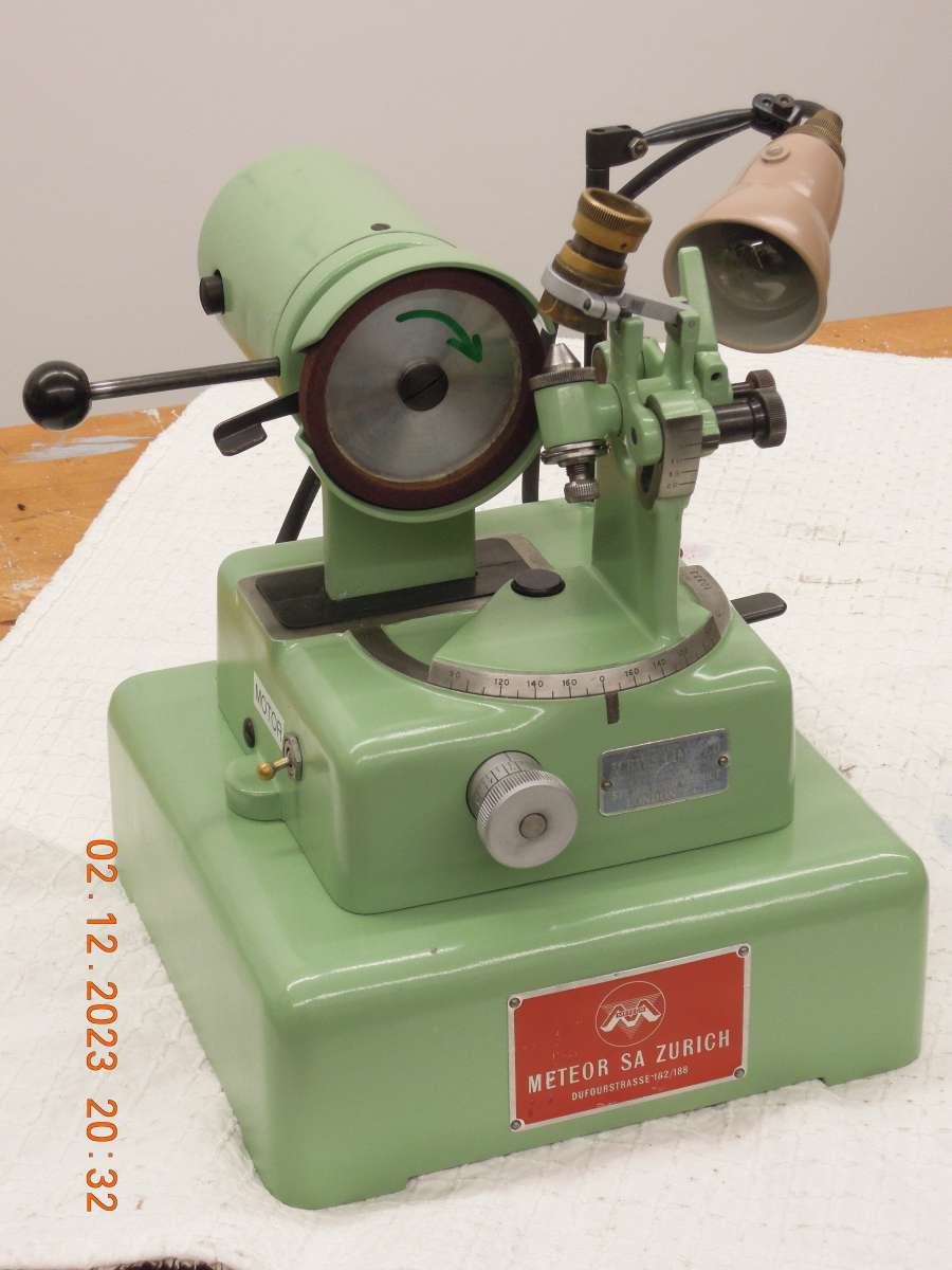
Meteor drill grinder

Advert

Meteor drill grinder

Home Forums Workshop Tools and Tooling Meteor drill grinder

Viewing 14 posts - 1 through 14 (of 14 total)
  • Author
    Posts
  • #697561
    gerry madden
    Participant
      @gerrymadden53711

      Finally today I have completed and re-assembled my drill grinder. Its a neat little machine made by a Swiss company called Meteor. There is a little bit about them on lathes.co.uk but as they rarely seem to show up in the UK I thought the forum might like to see one.

      DSCN0445

      DSCN0441

      The wheel is slightly out of balance but despite that it cuts nicely. The balancing weights sit on back of the wheel and are rusted up. I’ll have to make three new ones which is a bit of a faff so that’s a job that might have to wait.

      Unfortunately I don’t have a manual for this model. In fact I don’t even know the model number as the original machine plate has gone missing. I did however find a manual for what I thought was a similar machine on the internet. Unfortunately it must have been re-printed a number of times before getting on the net, as the critical diagrams regarding the initial set-up position for the drill in the chuck are somewhat ambiguous. As a result I seem to be creating negative clearance/relief angles on my trial parts !

      I’m a bit puzzled by this as its should all be quite straight-forward and intuitive. And it IS straightforward when I articulate a large 13mm drill in the same orientation of the tiny 2mm one in grinder’s chuck. One source of confusion is that the manual I have says “The optics of the microscope present the drill in a mirrorsymmetric inversion” but unless I’m slowly going round the bend, this doesn’t seem to be the case on my machine. But clearly, SOMETHING is not right.

      If anyone has a similar machine perhaps you can clarify the correct orientation for the microscope “cross-hairs” (as my manual calls them) against the drill cross section? Mine has no markings or detents to ensure this is correctly set after dismantling. Where I ‘think’ they should be set, might be the error that I clearly have.

      Gerry


      Advert
      #697563
      JohnF
      Participant
        @johnf59703

        Hi Gerry, Have a look on the groups.io under oldswismachines group search Meteor & Christen

        https://groups.io/g/oldswissmachines/topic/christen_drill_grinder/102092182?p=,,,20,0,0,0::recentpostdate/sticky,,,20,2,0,102092182,previd%3D1701596034196528688,nextid%3D1691056164506710618&previd=1701596034196528688&nextid=1691056164506710618

        I have a Christen and the full instructions on pdf — if you want these message me with your email

        John

        #697564
        DC31k
        Participant
          @dc31k

          There is a manual here for a machine with a different base, but a similar looking top end:

          https://forum.strojirenstvi.cz/download/file.php?id=103912

          #697628
          Mark Rand
          Participant
            @markrand96270

            It’ll be a KBS.3 if the chuck goes from .008″ to .125″

            or a KBS.6 if it goes from .008″ to .25″

            It will sharpen left handed and right handed drills, so presumably you’ve managed to set it up for the former. 😀

            I’ve got the larger ME.14 that goes from .125″ to 1.5″. It didn’t get any bids in the auction that I bought a Record 25 vice from, So was offered at the starting price of £50 + auctioneer’s rip.


            Unfortunately, I can’t help with a manual.

            #697652
            noel shelley
            Participant
              @noelshelley55608

              I have instructions for both the Brierley ZB32 and also the Clarkson attachment, though neither work like your machine. I can try to copy them if they would help. One point to note is that ANY imbalance in the wheel will effect the finish on the drill bit. I would deal with this before any serious trial of the machine. Good luck Noel.

              #698267
              Howard Lewis
              Participant
                @howardlewis46836

                Not being familiar with the machine, so purely guessing from the photographs.

                Having the machine to hand would make matters so much easier.

                The drill would be set with one cutting edge horizontal.

                The large horizontal scale would be set to give the 118 degree point angle.

                The higher vertical scale would be set to give the clearance angle (For four facet grinding, 30 degrees secondary clearance, and then 10 degrees primary clearance)

                The cut would be applied using the small handwheel on the front,

                The wheel would be traversed, using the lever behind the wheel head, unless the lever on the right of the base provides the traverse?

                The brass microscope would be used to check when the edge had been cleaned up, to minimise the quantity of metal removed.

                Having cleaned up one edge, the drill would be rotated through 180 degrees (Hopefully locked by the small black pin on the right) and the grinding process repeated.

                Then a final skim of the first edge, to endure that the lips are of equal length.

                Or should it all be the othjer way round?

                Some experimentation should clarify matters

                IF I have guessed correctly, the drill should then be sharp and cut to size.

                Please tell me if I am wrong.

                The awkward bit may be ensuring that when the holder is locked in position, to set the cutting edge horizontal.

                Howard

                #699302
                gerry madden
                Participant
                  @gerrymadden53711

                  Thanks for all your information chaps and useful to read other documents on this type of machine.

                  The good news is that I seemed to have solved my problem by playing about. The specific issue I had was to do with how the drill was presented to the wheel. Documents I had all referred to “aligning the cutting edges to the microscope crosshairs”. Perhaps mine is an older version but I had no crosshairs, only a crude silhouette, which you can see in the picture below.

                  DSCN0450

                  When looking through the microscope you see a view like this….

                  DSCN0447

                  Its therefore almost obvious that the diametral edge of the edge of the silhouette can be used as one of the pairs of lines in a set of crosshairs, and the tip of the drill can then be orientated as per the manual. All well and good.

                  Unfortunately microscope tube has a plain outside locating diameter and this sits in a plain clamp ring, as you see below.

                  DSCN0448

                  Orientation of the drill to the wheel therefore ultimately depends on the orientation of the microscope in its holder. Strangely there is nothing mentioned in the manuals about this or marks on the grinder to ensure after removal, the microscope can be easily reinstalled in its correct position. Basically I had to determine this by working backwards from where I ‘thought’ the drill should touch the wheel, to replicating the view that one is supposed to see in the microscope. After doing this, it seems to work. But whether my selected microscope position is exactly the same as the grinder maker would have used, I have no way of telling.

                  In my original post I did say that I seemed to be getting ‘negative’ relief angles in my early trials. This may have been partly to do with incorrect drill orientation, but I believe it was also partly an optical illusion. This work is of course a compound angle problem with curvatures, and consequently its easy to misjudge what you are looking at, or measuring, in such situations when working with such tiny and already worn/damaged drills. From now on, I don’t try to just ‘lick up’ the cutting edges, I simply recut the whole face.

                  I have now resharpened about 25 old drills and confirmed each one with a drilling trial. I’m happy with the results. What I have noticed though is that there is considerable variation in the length of the chisel-edge which is of course a direct consequence of the thickness of the spine of the drill. Unfortunately long chisel-edges tend make the initial diameter of the drilled hole oversize as the drill ‘swashes’ around before its OD can control its position more precisely. I will now have to experiment with truncating the chisel edge length to further improve hole quality, but this is all microscope work and not so easy to do.  ….Might be easier just to buy some top-quality drills, if I want top-quality holes. 🙂

                  Gerry

                  #699328
                  Versaboss
                  Participant
                    @versaboss

                    Hi Gerry

                    I used such a grinder a lot (it is sold now), but mine had another microscope system which was not removable. Or at least I never removed it. The ‘crosshair’ in my case was two quite large spikes for aligning the drills. To set up the microscope in your case I would insert the largest drill possible in the chuck, one with a correctly ground tip, and adjust the drill so the cutting lip is horizontal on the grinding wheel. Then use that position to set the two edges of the (kind of) ‘crosshair’ to the lips of  the drill. Easier to do than to describe, I think…

                    The problem with the chisel edge is, I beliebve, because you don’t use the machine correctly. You say “I simply recut the whole face.”, that’s wrong if I understand that correctly. You should grind a four-flat point, that has no chisel edge. First grind the cutting lips with clearance of say 6° – 8° (that’s waht I used), then sweep the chuck holder to the lowest position (around 25° iirc) and grind the secondary flats until tha 4 flats meet in a point. Then your ddrills will not cut oversize.

                    Kind regards,
                    Hans

                    (who has not yet found out how to quote)

                    #699332
                    bernard towers
                    Participant
                      @bernardtowers37738

                      I think Hans means they should look like this. Hopefully!IMG_0405

                      #699375
                      gerry madden
                      Participant
                        @gerrymadden53711

                        Hans, thank you for your interesting input. I had seen descriptions of the four-facet cutting but noticed that none the small drills I had, showed this feature.   They were from different sources but were all essentially the same, so I just copied it. Perhaps they were ALL just cheapo’s !

                        But what you have described sounds actually very easy to do so I will give it a try tomorrow. Currently to grind a drill takes only a minute or two, so making a two-stage cut just isn’t a problem. And you are right, it will minimise those long chisel edges.

                        Nice picture Bernard. Shows it clearly.

                        Gerry


                        #730209
                        rickkr
                        Participant
                          @rickkr

                          I have recently come into two Meteor CH 1 drill grinders.  They appear to be identical the what is shown in the manual for the KBS 3, link posted by DC31k.  Capacity is up to 1/8″.

                          Meteor CH 1 Drill Sharpener 03 05-08-24 640

                          I’ve worked through the manual and have managed to sharpen a few drills down to about 0.050″.  Here is the 4-facet point geometry on an 1/8″ drill.  I’ve not worked out the process for the web thinning operations, but will keep trying.

                          Meteor CH 1 30 05-07-24 640

                          Rick


                          #730295
                          noel shelley
                          Participant
                            @noelshelley55608

                            Hi Rick, It may be the picture but the facets of the drill shown do not appear equal. This is where 4 facet sharpening gets difficult – in getting the faces equal. Gerry, depending on the geometry of the machine the amount by which the drill bit sticks out of the chuck or holder may affect the clearance angle. If there is any vibration due to wheel imbalance this will have an effect on moving ways or parts, giving inaccuracies that may or may not be important. Good luck. Noel.

                            #730345
                            rickkr
                            Participant
                              @rickkr

                              I think they are unequal.  Just my less than perfect technique.  First one I did that was good enough to even show.  Still working out that technique. I’ll have to watch for that as I work, for what it is that is causing it to be unequal, given the precision-ness of the settings and movements.  Is it more a matter of doing everything exactly the same, now to the number of strokes across the wheel until it doesn’t anymore?  Thoughs?

                              I have much more experience on the Tormek, with 4-facet points, but it has its own foibles.  Tormek goes down to 1/8″, so this one complements/completes the range.  I’ve not tried many under 1/4″ on the Tormek as it isn’t as precision or repeatable with the smaller sizes.  (Or should I say, the inconsistencies aren’t as evident with the larger sizes…)

                              Rick

                              #730413
                              Howard Lewis
                              Participant
                                @howardlewis46836

                                Not knowing the machine, but it might be possible to set it up, and use it, in the same way as a Worden for four facet grinding.

                                The Worden drill grinding accessory hilds the drill on a 31 degree wedge (188/2 = 59.   90 – 31 = 59)

                                I hold the drill in a square bar, with the cutting edge set vertical. On the wedge, this presents the drill to ther wqheel at an angle of 59 dgrees. I made a fixture so that the holder is on the 31 degree wdge, and the cutting edge of the drill bears against a vertical face on the fixture. The drill is then clamped in the holder ready for the square holder to be transferred to the inclined fixture on the grinder.

                                With the completed holder rotated by 30 degrees, (Your choice of clearance angle) the secondary clearance is ground on one side of the drill.  By rotating the sqaure bar by 180 degrees after each pass, excessive cutts are avoided, hopefully, equal off each lip, and the lips should be equal length.

                                Once the secondary clearance has been ground, the holder is rotated for grinding the primary clearance. So reset the holder from 30 degrees to, say, 10 degrees and take a lick off one lip. Rotate the square holder, and take a lick off the other lip. Continue doing this until you have nicely ground four facet drill.

                                Howard

                              Viewing 14 posts - 1 through 14 (of 14 total)
                              • Please log in to reply to this topic. Registering is free and easy using the links on the menu at the top of this page.

                              Advert

                              Latest Replies

                              Viewing 25 topics - 1 through 25 (of 25 total)
                              Viewing 25 topics - 1 through 25 (of 25 total)

                              View full reply list.

                              Advert

                              Newsletter Sign-up