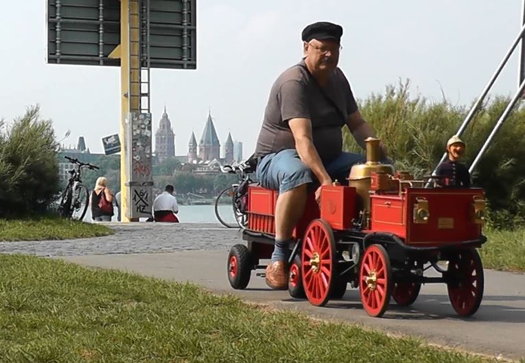
I hope I understand your question correct. The anti clockwise rotating wheels is an optical illusion. The Video is made with 25 pictures per second and it was made with real pictures ,non interlaced. So if the wheel is turning it could be that fractions of the picture s you see give you the illusion that the wheel is standing still while driving or go slower or faster. It is for me easier to explain in german than in english . I hope you can understand it.
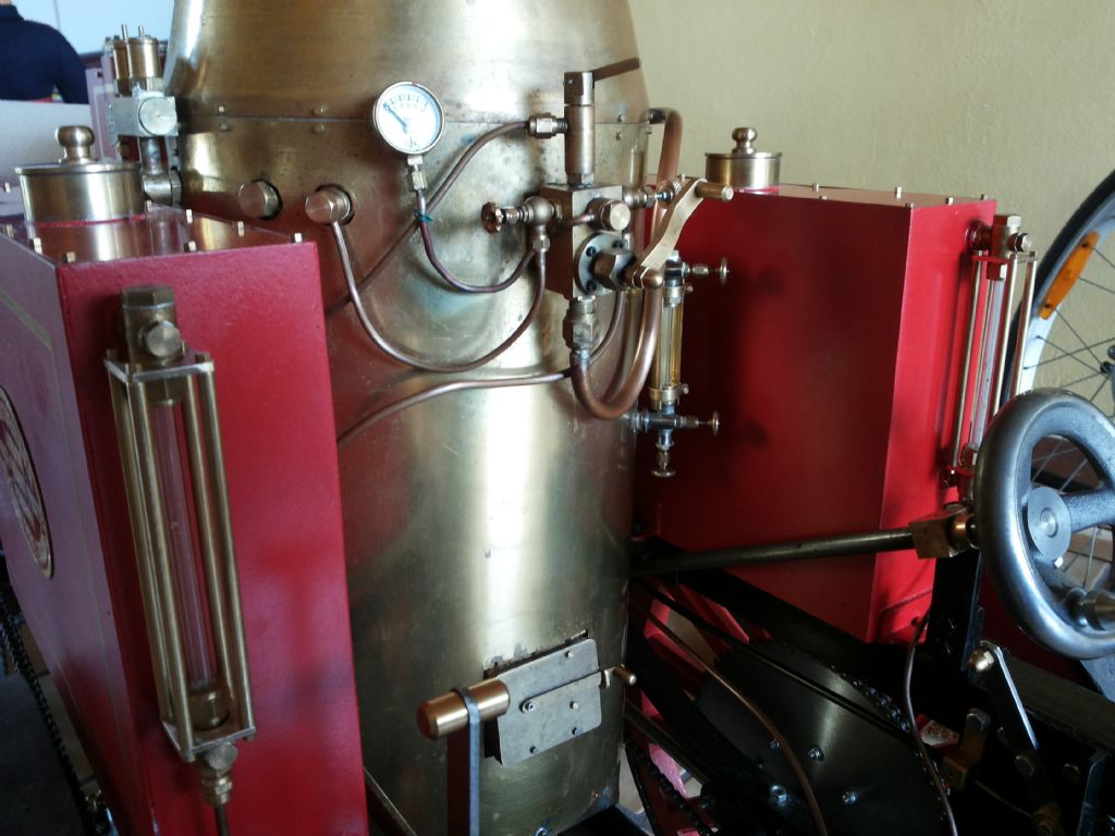
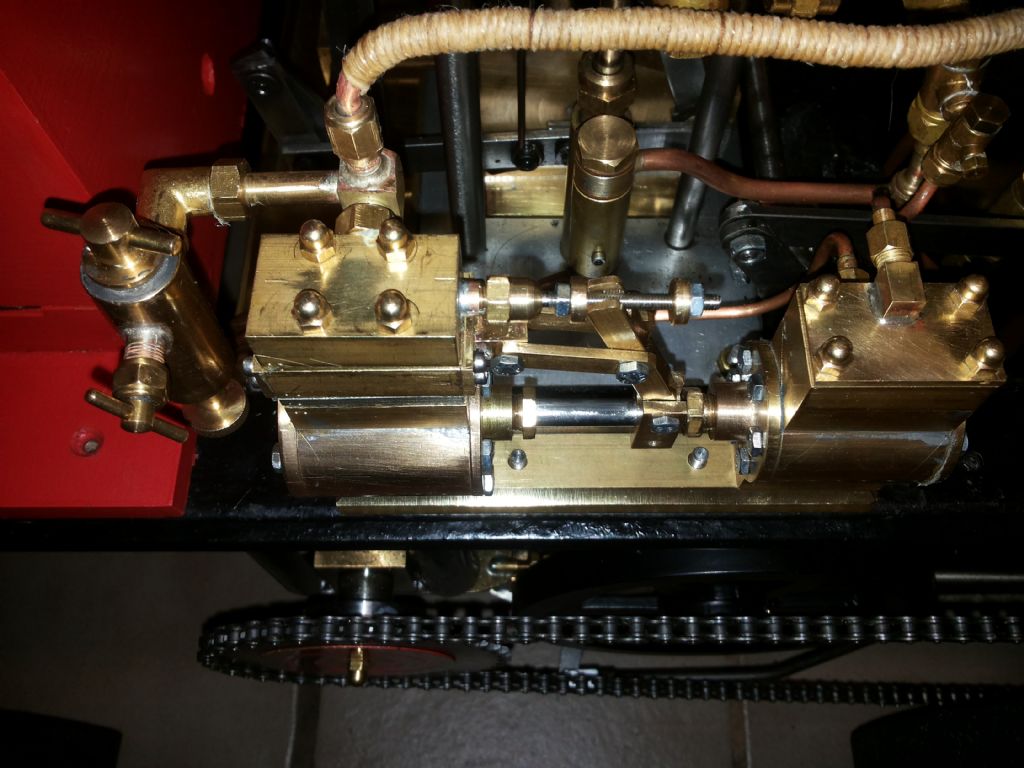
The device between the front box and the water tank is a horizontal steam donkey pump. The amount of water is big enough to take a coffee or have break and the water level in the boiler keep stable.
that is easy to explain ,because the front lamps need some energy. This brass cylinder is a fake fire extinguisher and is big enough to hold inside 3 AAA batteries or a Laptop lithium cell. The handle on the top is the on off switch for the lamp. I do not want to bring cables on the backside of the front plate and so the Idea came up to make the fake fire extinguishers. And I tried to make them realistic. In my second video I show how I made the lamps and the batterie holders. The lamps are with led diodes equiped and have an automatic connecting mechanism by mounting.
As i said experience is the only thing that counts, therefore i made protectors for all my watergauges and i think it gives a better look as before.
After the run and cleaning i found that both eccentric cranks of the engine are not proper fitted on the shaft. After some discussion with a friend i decided to add loctite 638 and screw it as before. The cleaning action was a little bit difficult , but it was a straight forward job on one side. On the other side the reaction of the loctite was faster then i can adjust it Ok. The result was the screw has no fit ,because of a very small misalignment. The idea to cut the thread again was a stupid idea the thread drill cracked and was partly in the bore.
I decide then to make the thread new on the opposit side of the shaft. Now i can not mix left with right. Always think positiv.
On our next club open day i drove with the new gear setup to the junction of the river rhine and main again. I had a much better driving performance faster with less coal and water consumption . On the background of the picture there is the city of mainz with the cathedral.
I am now in preparation for the next event in the mannheim technoseum the steam meeting 16 and 17 of september . As you see on the picture the little firefighter is eagerly waiting for the next event and his coworker with the watergun too.
the Mannheim steam event is now history and it was very nice in the museum called Technoseum. In the park before the museum there were nice areas to drive with traction engines and with my "fire king".
I made a video of our driving and i hope you can enjoy it. My fire king was in good working order and we had a lot of fun.
after the Mannheim steam event i drove at our club track and there was some knocking noise hearable ,but it was hard to find out on witch part of the steam engine. I recognized that it was good to strip as many as possible from the frame in the garage,because i was not able to bring the machine over the stairs in to the basement. With the front part,the side tanks and the boiler detached, it was easier to investigate the noise.
After stripping off i found that the attachement of the eccentric crank was not solid and there was lash.
I stripped the shaft out of the engine and i added a feather key groove.I made the feather key to a very strong fit.
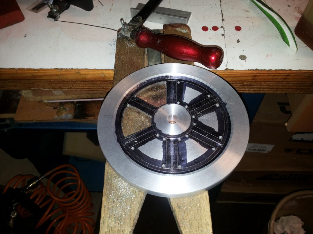
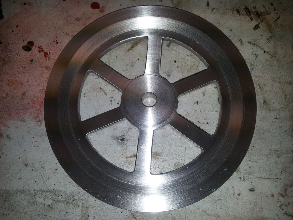
Now i hope that it will withstand the power of the engine. To get a smoother running of the engine during water pumping with the fire pump ,I decided to add a flywheel. The material I had in stock.
The flywheel under construction
the end machining was made with a small round table on the milling machine.
It was a good exercise to do it ,if it is not heavy enough i made it from brass again.
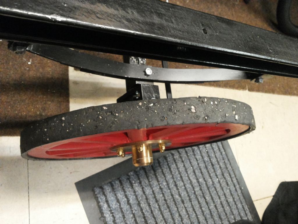
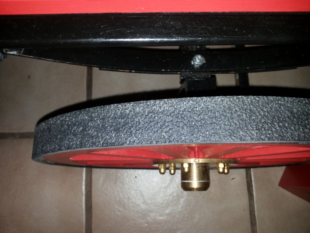
My rubber tires ,a 65 shore rubber, collects many stone from the road and they looked very bad after 34 Km of running.
So I looked for harder material . The idea came up to calculate how is the force where the wheel is standing at the road. With this calculation i had the idea it is nearly equivillant to a woman s heel. So i looked in google to shoe maker supplies and i found hard rubber in longer stripes. It was in a good price available.
The surface structure is like asphalt.
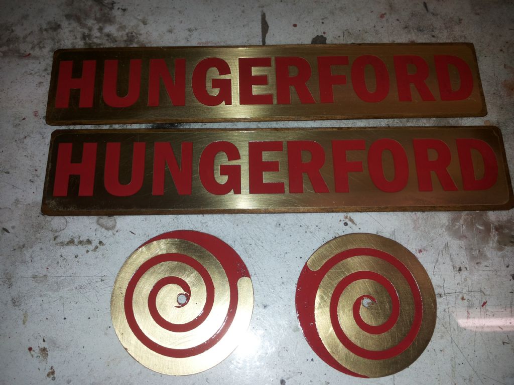
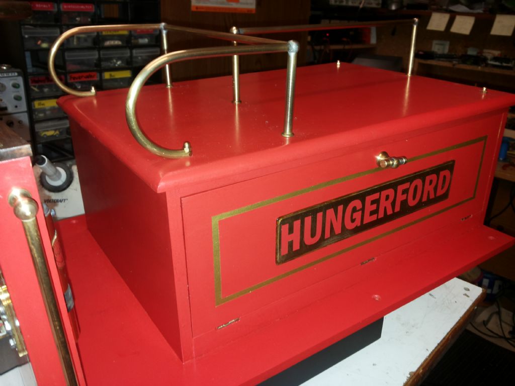
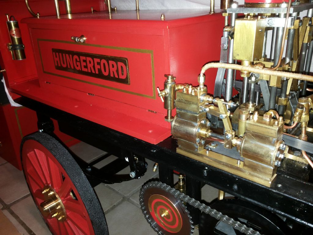
In between I made the etching plates for the town name. I decide my fireking had the nearest fit to the fireking witch was in service in hungerford as i have an old picture of it.
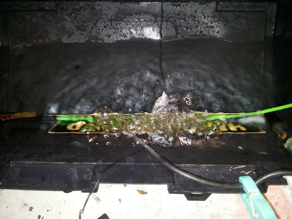
The large plate i was not able to make in my standard way .I had to do some improvisation. I searched in the house a larger dish. I had no success. As I want to clean my tool box I recognized that is the best way to use the empty box and made it quick and dirty.
It was very at the limit , the result was not 100% perfect but good enough to use it.
I had the problem that the etching was over 1 hour and the photo resist has some weak point on the downside of the letters.
Atached on the doors it looked like the original for me
i want to update my work. During driving downhill and under parking conditions I missed a brake system.So I looked in the workshop how I can add it, with not much work and in a way that it looks like it was made from the beginning. It cost me some days to find the best way.
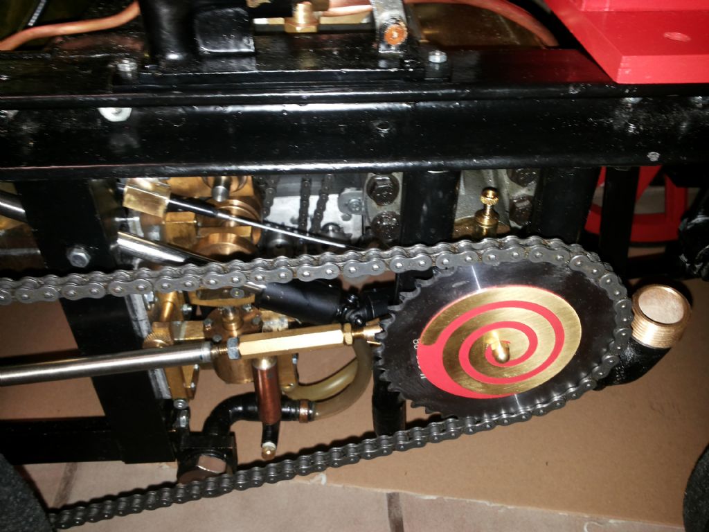
The decision was made to use the housing of the differential gear in combination with the brake shoe.The brake shoe was made by wood with rubber glued on it.
The difficulty was to find a routing for the brake cable. With some thinking and studiying my pictures I found a good way to combine the brake lever with the brake cable. I was able to use an old hole to attache the cable guide.
The brake was used with a spindle system. So it is not too big but powerful enough to pull the cable. To give you an idea please look to the pictures.
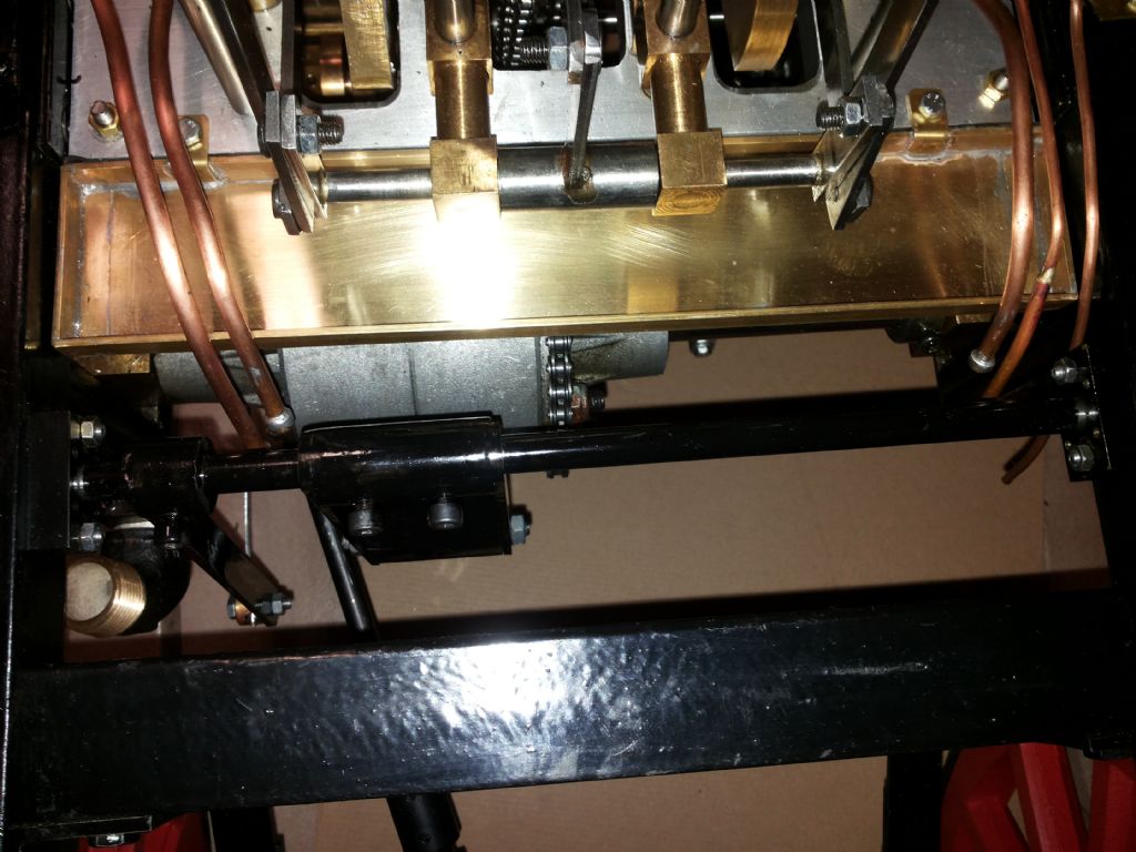
The break cable have 10 mm of clearance to the driveshaft.
Break shoe and shaft. To keep the housing from the differential gear more clean, a brass tub was added to collect the oil and water drops of the engine.
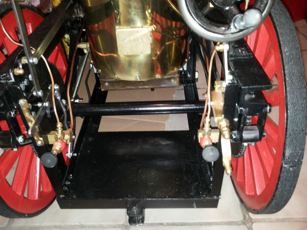
To find a place for the brake spindle and the sizing was not easy ,but at the end it looked as it was constructed from the beginning.The lever and spindle is below the steeringwheel on the right side.
And one thing I tried to make, a one hand using and driving possible. The left hand I use typical for the camera.
The next step is to build an automatic pressure dependable blower valve to ease the usage and keep the fire in a better condition. In my driving this year i forgot very often to use the blower valve ,because the driving conditions are very different between full load and no load. The automatic valve keep the pressure around a half bar under the safety valve set point and if the pressure drops a half bar the blower starts automaticly. That gives a very good water usage and a good burning fire.
In my 5 inch gauge small locomotives this was a very big improvement.
At first many thanks for the nice replies and I wish a good steaming in 2018.
I made some progress in planning and puting things together.
For easier use of my fireking I constructed and made an automatic blower valve. This blower valve opens and close automaticly the steam blowing into the chimney. The basic parts are the housing which is splitted in to funktions at first a steam valve and a diaphragm. The diaphragm is realised with an o ring and closing part pre tensioned by an adjuster nut and a spring.
The valve is connected by a bar with the diaphragm. If the pressure is low the spring give tension to the o ring and the valve is open. If the pressure is rising to a certain point ,70 to 100 psi depends on adjustment , the steam pressure is higher than the spring tension and the valve was closed. In a good setup the hysteresis is about 3 to 4 psi. The anthracid coal is much better to control ,because if you add water or the pressure drops the blower valve react immidiatly. The cut off should be 3 to 4 psi under safety valve pressure. With this valve you have less cinder and a better fire. The behaviour is in easy words like you have a much bigger boiler.
Secondly I realised that my, very fine made, donkey pump is to small for holding the water level in the boiler.
Last year I decided to use only one cylinder in my fire pump setup. The second one came in a box with parts. By chance the idea came up to use it with some small modification to build a more powerful steam donkey pump.
So I made new a smaller water cylinder in relation to the diameter of the steam cylinder . The valve work of the steam engine is a functional copy of the smaller one. Due to the fact that I did not open the smaller one so I had some thinking how I have to made the parts.
I am very satisfied, with no mistake the pump get in function. It is always fascinating at the beginning there is the idea and the material ,then brain work , hand and maschine work and then there is life.
I hope the steam tests are in the same way.
I put together all in a small video I hope you can enjoy it.
I just registered because I was so impressed with every aspect of your build, your videos and the choice of music. It's people like you that make this website so enjoyable for this old Florida guy to read and learn from !
I attached my steam pump at the frame as replacement for the smaller pump. I hope that my calculation of the pumped water is now OK . I think there are some drawbacks by running in ,but that is normal.
I had some good progress by installing the pump, only one small change at the the pipework have to be done.
And here is a close up.
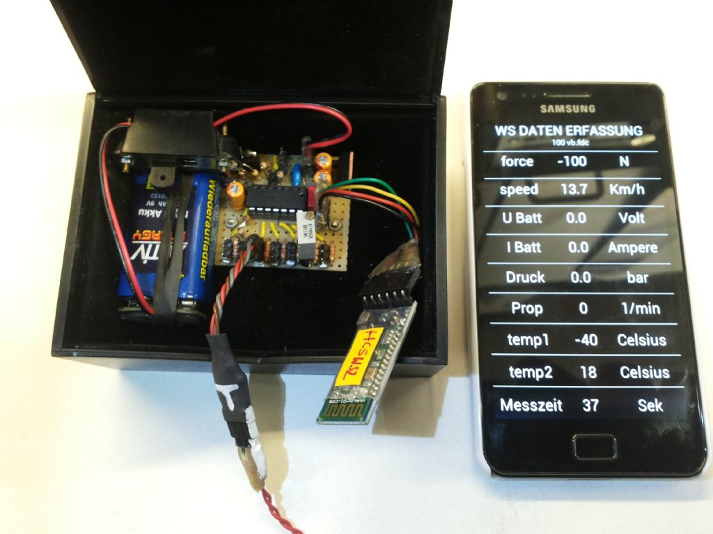
In the time between building I started an additional project ,because I want to know the power output of my models. It is a device which enables me to collect data for my private imlec competition. I hope that i can find something to improve the efficency of my models.
With this device I can measure force ,speed ,pressure,rotational speed, temperature with thermocouples and voltage and current for electric models.
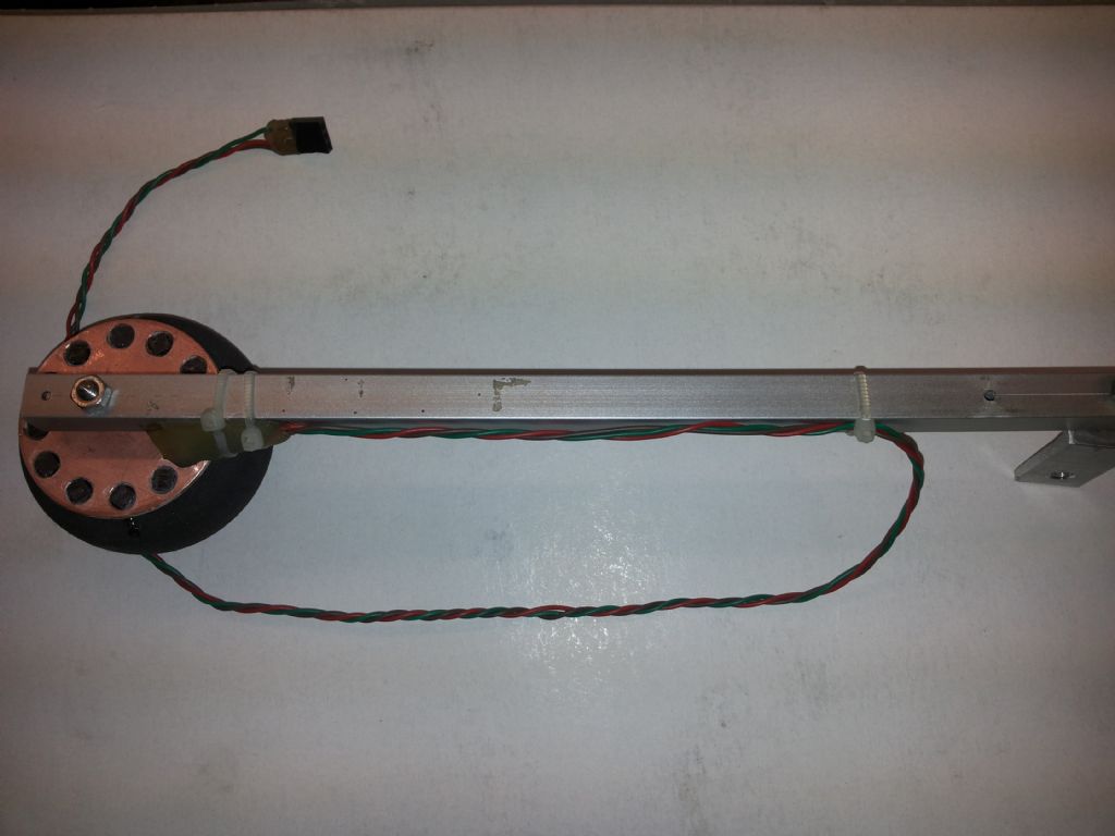
All measurement data have been collected by a small computer and is send via blue tooth to an android phone. At the phone I wrote the the data accquisition software in basic. All sensors and amplifiers are constructed at a low cost, but as accurate as possible. The force sensor is made with a strain gage force sensor from a cheap chinese luggage gauge. The measurement range is up to 400 N .The accuracy by my calibration is around 2 to 4 N . The speed sensor is made from a model aeroplane wheel attached with a magnetic wheel and a hall sensor. Precalibration is made but not a test in reallity.
it is nice to see that I am not alone with my thoughts.
Here are a few descriptions of my devices .
The data collection is based on a PIC 16F684 processor with 10 bit resolution. I have 7 analog channels and two digitals. 2 Channels are dedicated to Volt and Ampere the others are with flexibel input that mean 0 to 5 V input.With jumpers the Ampere channel could be equiped with a pre amplifier for a current clamp.
I want to have all modular ,because I want to build a test bench for my model aeroplane props and motors with the same unit. Temperature I can measure with a simple NTC resistor and with thermocouple amplifier type K.
The force measurement is based on a chinese luggage gauge. It spends the strain gage element. An instrumentation amplifier with faktor around 1000 amplifies it to the real calibration.
The pulse wheel is made with 12 magnets these give 6 Pulses at the hall sensor.
All is build on prototype boards and a 9 V accu can power it all for 1 hour as long as my android phone run in full power mode.
All is testet ,but I am waiting to make real measurement with better wheather conditions.
The pressure sensor is a cheap chinese sensor with 12 bar scale and integrated electronic. I will see how good a 10 € sensor could be when I have it.
At the moment the system can send 5 to 6 full data frames per second. For more static measurement it is good enough. And all is running on 9600 baud.
For an indicator I think the rate have to be increased. And a good contactles displacement sensor have to be used.
Here are some pictures for better understanding.
Data acquisition send via blue tooth to the android phone software
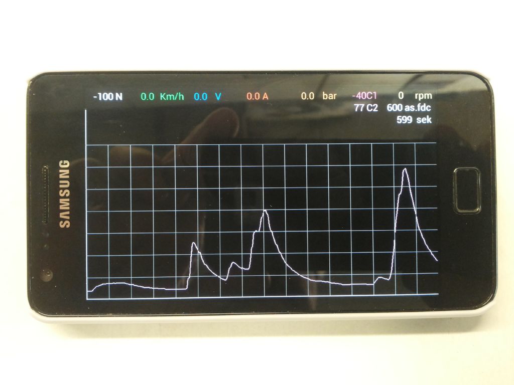
This is a graphic example
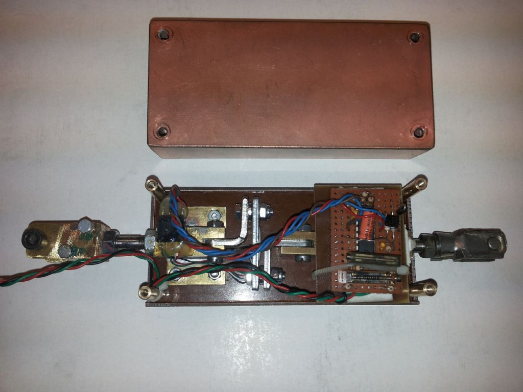
The force transducer
On the left side is the fixture to the waggon ,in the middle the luggage gauge and on the right side there is a mechanical guide to eliminate side forces. On top the amplifier.
By chance i killed one element .One wire in the middle was detached. So I was forced to order a new one
for 5 €.
The pulse wheel
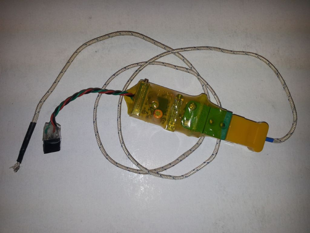
The thermocouple amplifier with a cheap chinese element
I think it is a kind of overkill , but I hope I can find some room for further optimization.
I want to update my work with a test ride under steam pressure.
First test ride after some improvements over the winter .The new donkey pump learned under steam what to do. With temperature the flying piston was very often sticky at the beginning. After some run in it worked fine. The automatic blower valve worked good ,but the spring need a replacement in a stronger one. By chance I noticed that my air pressure test gauge count the wrong value to less. And tightening means that the coil is nearly blocked.
At the end of the day came the "lovely" clean up work .
Here is a video of the ride.
Steam is always an adventure . I hope I can test my measurement equipment in close time frame.
here is an update of my activities. We had our steam up at my local club the DBC Rhein-Main. The street steamer had now a new colleage with a traction engine. And a new setinel " elphant " made it first rounds in the public and I had my partly improved Fire King with new donkey pump and automatic blower valve and I added a small car for children to sit on. There were a lot of steam and electric locos on our club track.
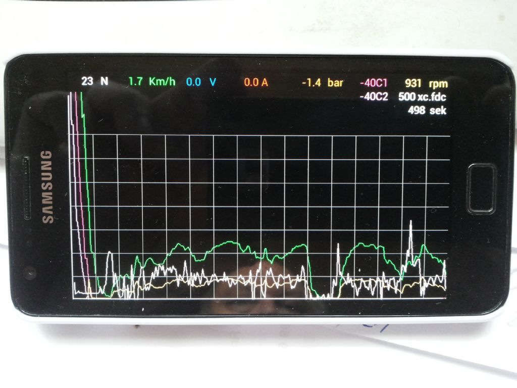
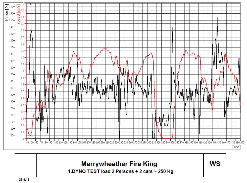
In between with lot of improvisation I made my first real test with my measurement unit with the dyno and the pulse wheel and so on. There is a picture of the raw data on the quick look display on the phone.
The green line is speed and the white line is the dyno force. As I know now there is small lash in the coupling bolt and the road surface looked smooth ,but because of pavement it is rough with some noise in the dyno .
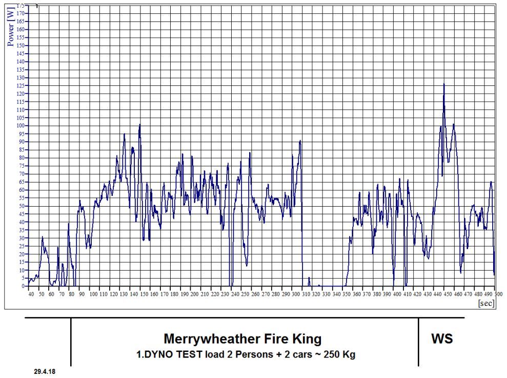
This chart is the averaged raw data of the dyno and the speed which is calculated from km/h to m/s to calculate the power in Watt. See next chart.
By the first shot I think it is not bad ,but I have some idea for refinements.
There is a video of the steam up at out club area.
You should expect the noise in the data, the engine itself introduces noise as a result of the reciprocating masses. It even happens with locos running on rails. Maybe some better fitting pins in the couplings could help a bit but don't try to do too much mechanical damping. Just do it in the processing of the raw data, as you have done.