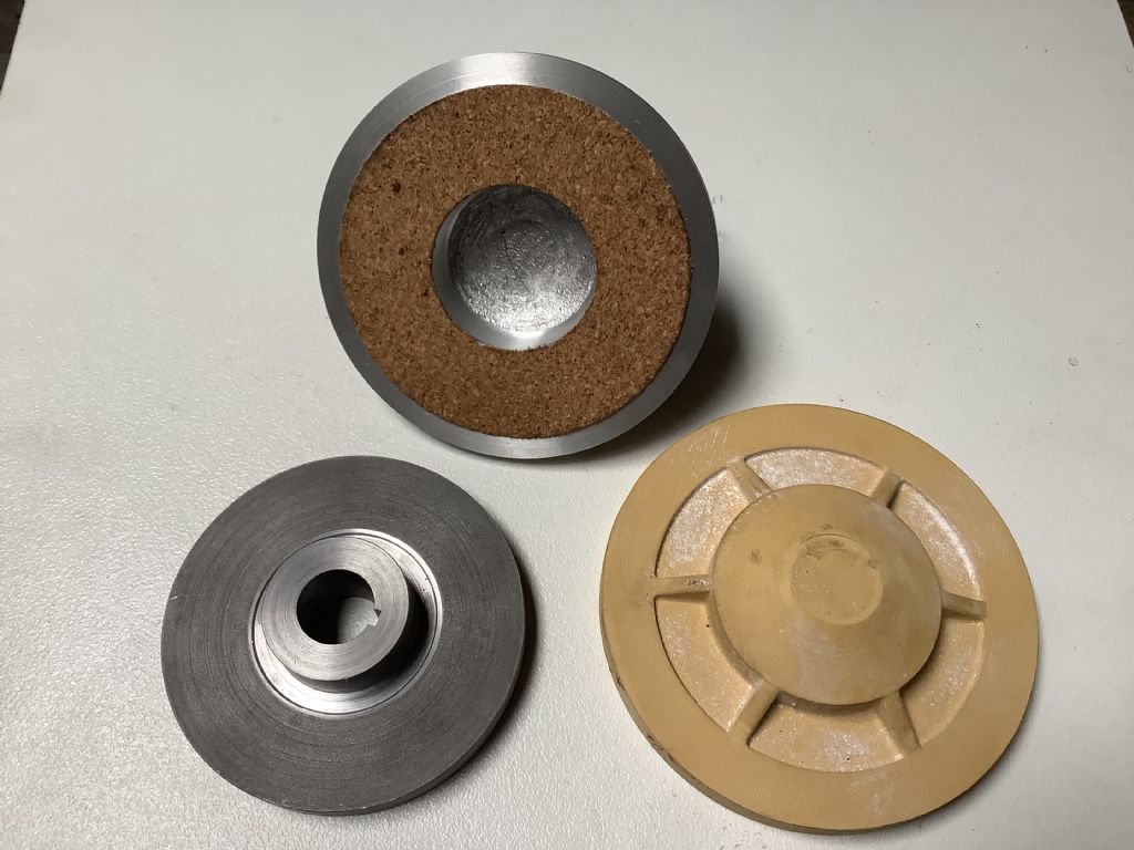
Thank goodness for a shed as today the “ big wet” arrived in the form of 235 mm of rain in the last 24 hrs. The shed did have a moat around it but in some places they had over 600mm in the same time and that’s enough to wash a shed away ! I have made some of the parts for the clutch ,these being the outer pressure plate and the inner plate. I still have many parts large and small to make and fit but I am trying to follow the same construction methods as used on the full size tractor. This is not always easy as some of the details are not visible in the drawings that I have and I don’t feel I can ask the owner to take the original apart. Photographs to follow.
I have no idea how much of an issue it might be in this situation Fred, but you appear to have used reconstituted cork rather than 'real' cork. The 'glue and granules' format of that friction surface may just fall apart in use.
This is an area that I may have to experiment with and may need to try different friction materials. I do have other sheets of cork but they are as you said granulated as that is what was available. Have you any suggestions what I could use as an alternative ? The sheet only needs to be approximately 2.0 thick.
Fred.
Unfortunately real cork is getting difficult to obtain and is now rarely used for wine bottles. However, you may find that a home brewing shop will stock real cork stoppers and your solution would be to slice those into suitable segments, glue them in place and sand to an even thickness. They will certainly provide a longer service life and, provided that you use a suitable adhesive, they will be immune to oil contamination. Cork is used this way in full scale motorcycle clutches with oil baths!
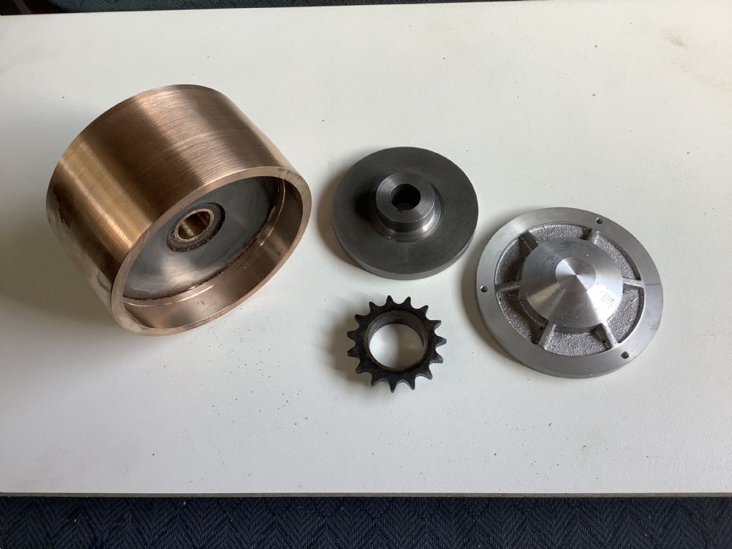
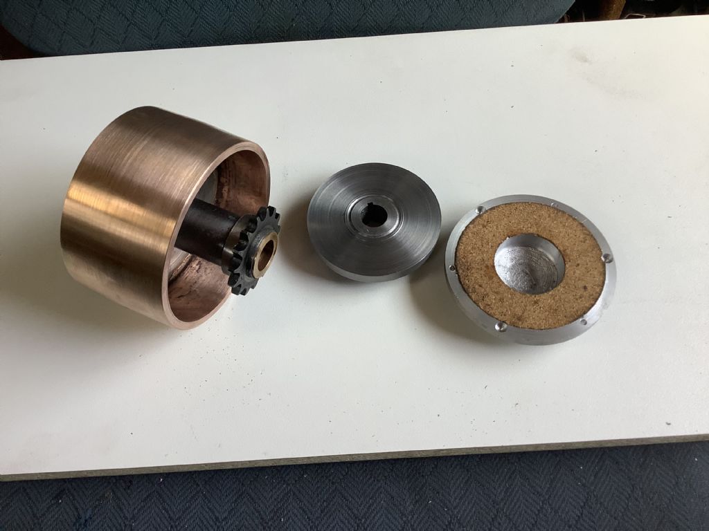
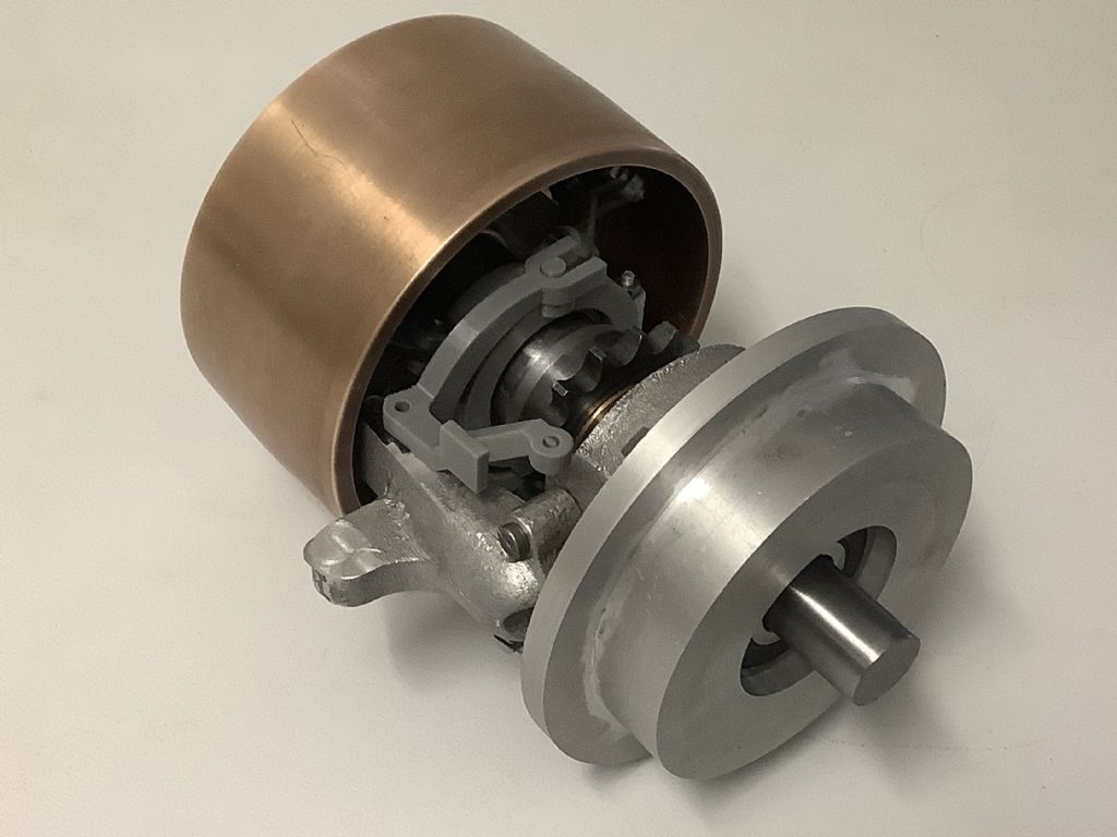
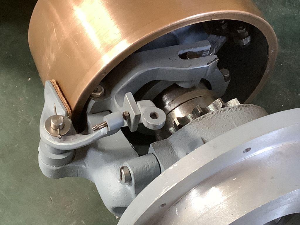
The photographs show the heavy part of the clutch (1.7kg) but I have yet to make the parts that make it work. The bronze outer part started life as a bearing from a large steam engine in the local sugar mill – I bought it from the scrap metal “ shop” one of my favourite places to visit! All the waste will be returned to them as I now have an ice cream container full of it. It was one of those pieces of metal that I had been keeping for the last thirty years for that special job. As time is not on our side it was about time I used it for that special project. Tomorrow I will be working on the levers and cams that make the system work and hope they fit in where they are supposed to. The steel disc in the centre is the drive from the engine and the face inside the drum and the outer disc are squeezed on to it to take up the drive.
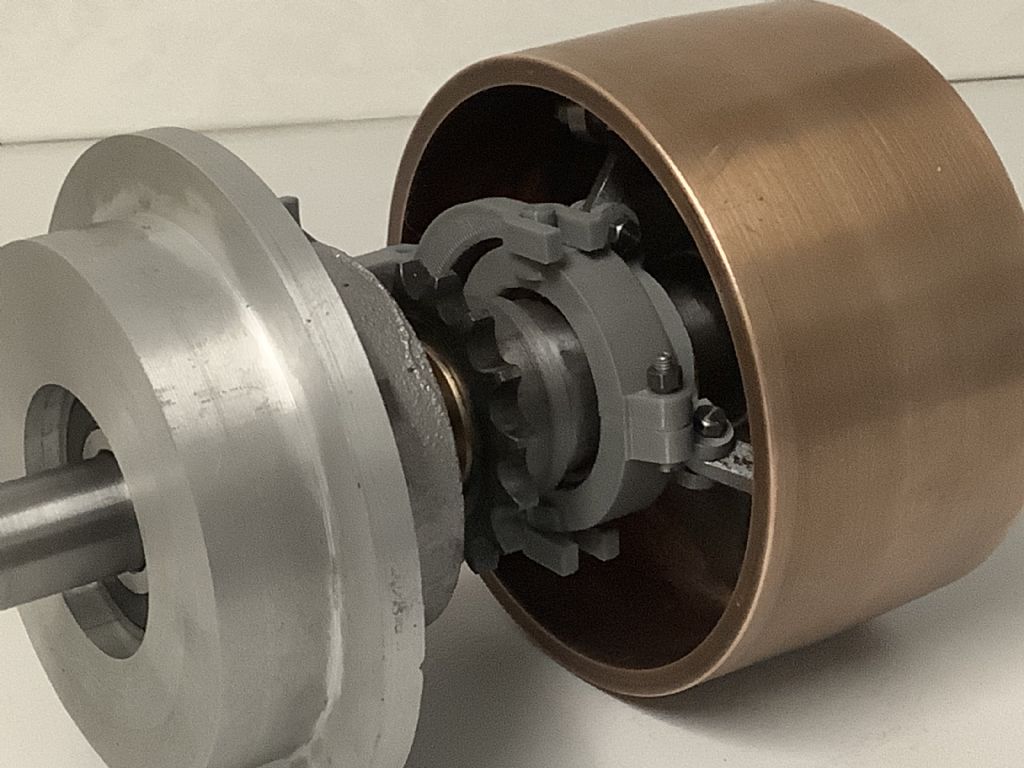
Today I did more work on the clutch and also one of the main bearing housings. I 3D printed the lever part to check that it would both work and fit when made from steel. I do need to make the arms stronger as the force needed to work the system would probably cause them to bend or distort. When pressure is applied by hand the clutch takes up the drive very well, probably due to the action of the cams and levers applying considerable force to the plates. I still need to fine tune the system but feel that it will not only work but also be very close to scale. As we are trying to stay safe the casting of the second crankcase has been put on hold for the time being – it will be made but not sure when! I can still work on the flywheel and injection system and be thinking about the cylinder head.
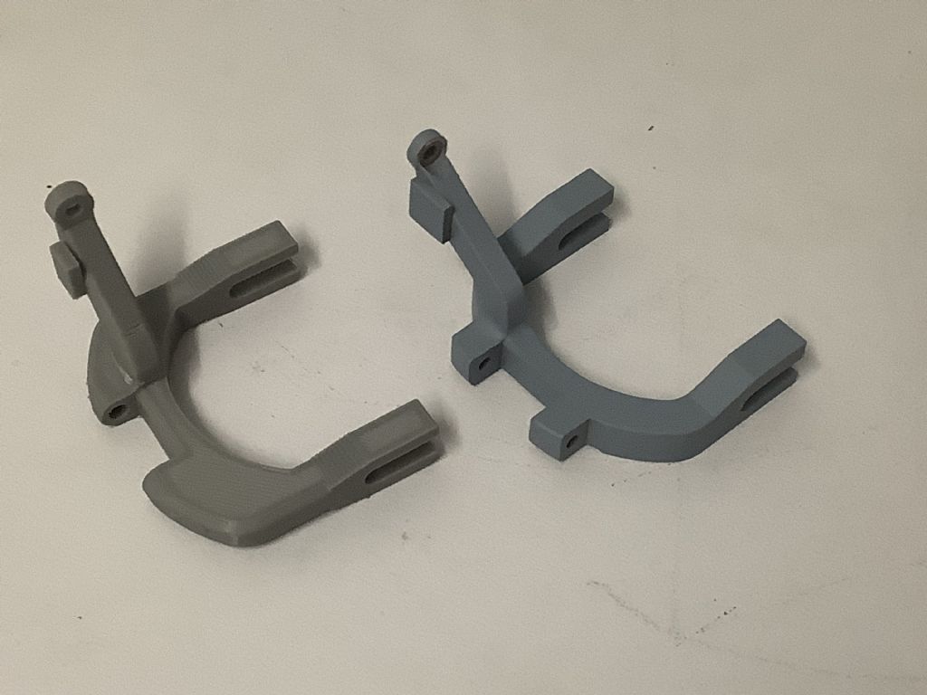
This is the end product of three days work! Not much to show for the hours it took to make. The one on the left is a prototype made in PLA on the 3D printer. The one on the right is made from steel with the main body being cut from a block of steel 65x54x16. The milling machine was very handy! The arm was made as a seperate part and pegged and silver soldered in place. The square part is for the brake application and has been riveted onto the arm. When the clutch lever is pulled back it engages the clutch and when pushed forward it applies the brake pad to the pulley and on this tractor is the only brake , later models were offered with an external transmission brake fitted to one of the gear shafts.
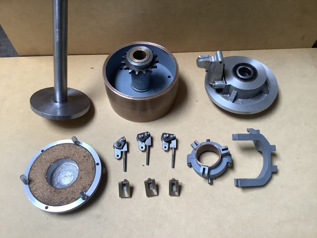
These are the 26 parts that make up the subassemblies of the clutch ( excluding nuts and bolts) and are now ready for the final assembly. I still have to make and fit the brake arm lever that presses on the outside of the pulley, but before I begin that I have to make a part for my digital height gauge as yesterday I had a disaster when the cover for the Myford caused it to fall from the table and on landing on the floor it broke the clamp that holds the marker point. This part looked as though it was made from stainless steel and was duly clamped together ready for silver soldering but on heating it appears that it was made from a type of white metal and began to melt! Oh dear, I now have to make a new part from another metal.
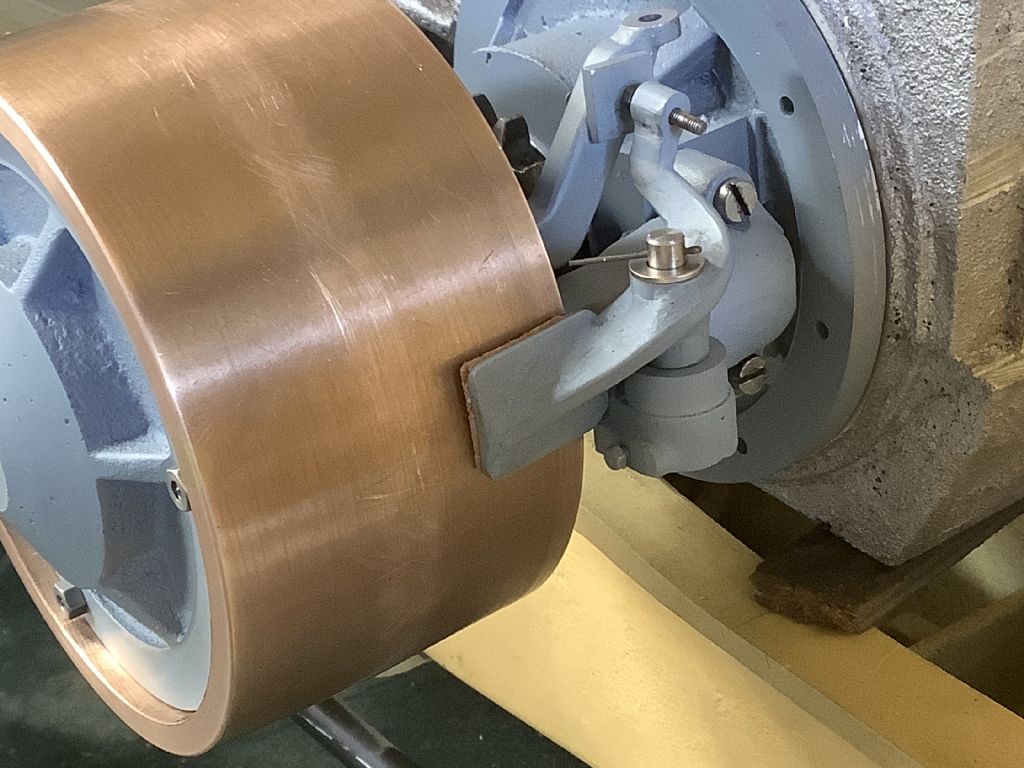
This weeks effort saw the completion of the brake/ clutch unit. Although the brake part is small it was not straight forward to make and fit and it took three attempts to bend the steel arm to shape and machine the hole at the angle required. The cheese head screws will be replaced with hex head bolts of the correct proportions. I am now looking forward to working on the other end of the crankshaft and making the flywheel and the injector cam that incorporates and advance retard mechanism.
I may not have posted anything on this build but I am certainly enjoying the journey that you are taking with this. Thank you for taking the time to post all of the photos
Thank you Dom and Derek for your comments and it’s good to know that this saga is being read and enjoyed. It has been going for quite some time and there is still some way to go. Yesterday was spent finalising the injector pump mechanism design and today I will prototype some of the parts on the 3D printer. The eccentric that drives the pump has a built in advance retard activated by bob weights.This changes the point of the injection and acts as the governor ( we hope) but some experimentation will be required in the initial set up. The whole of this unit sits behind the flywheel that has yet to be made. This part of the project is a challenge but that’s what makes life interesting!
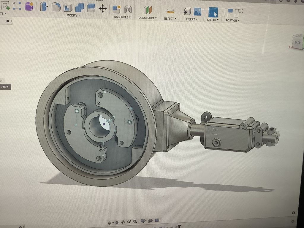
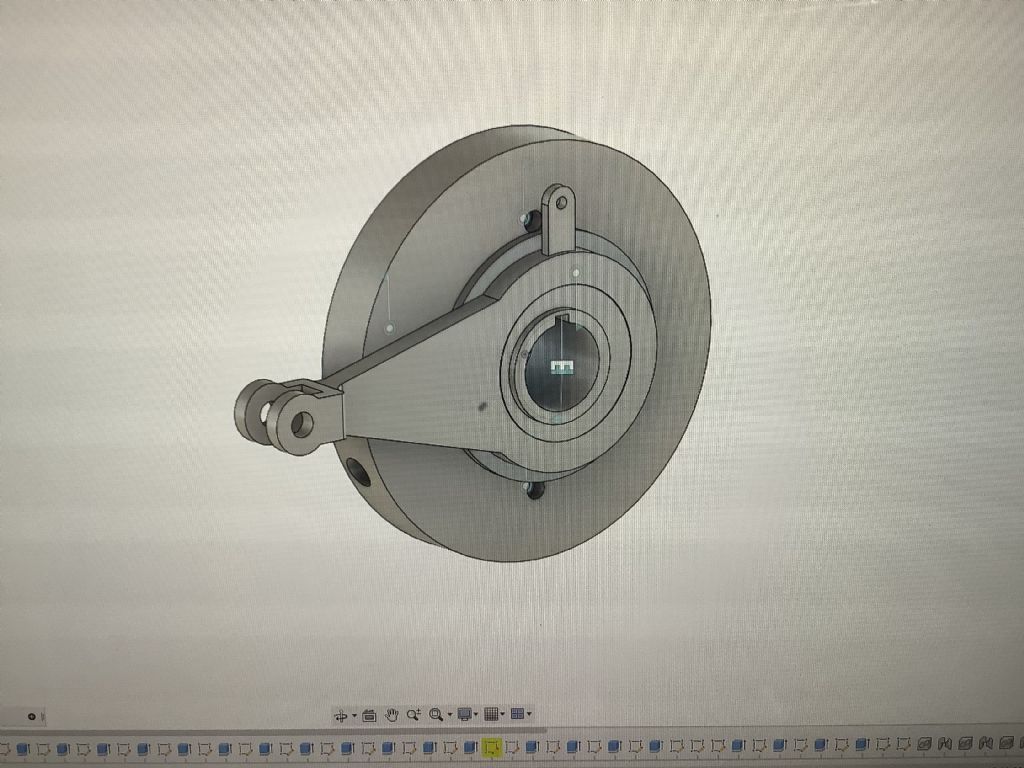
These are the parts that make up the injection system. The top view shows the bob weights that throw out and are connected to the eccentric by pins – springs and pins have been omitted. The lower picture shows the eccentric and rod – the small bar on the top is linked to and drives the oil pump. Apologies for the strobe effect from the screen.
The bob weights throw out and cause the eccentric ( constant stroke) to rotate backwards and this alters the point of injection but not the volume as this is controlled by a forked lever that alters the length of the stroke of the piston. I will show a drawing of this set up when it has been developed.
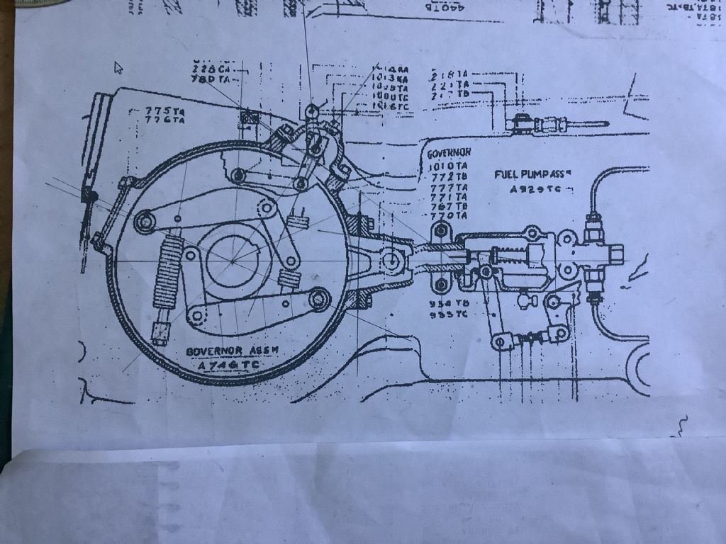
I am still not sure that I fully understand. Hot bulb/semi diesels are generally not very sensitive to injection timing. The lever system in the bottom right appears to limit the return stroke of the pump which would control the injection quantity but would also affect the timing.
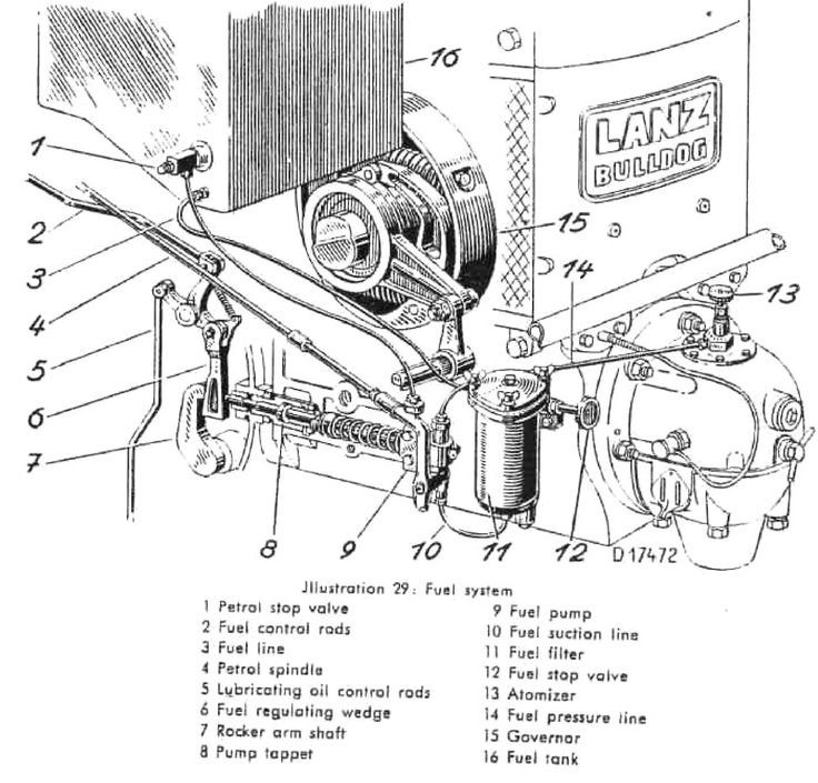
I am more familiar with the Lanz system which has a similar looking governor but the weights rotate an eccentric sleeve inside the main eccentric that controls the pump stroke. Engine speed is controlled by a wedge between the eccentric rod and the injector plunger.
Thanks for the information Roger. The system shown for the Lanz may be the same as used on the Mc Donald but on the information I have does not show it clearly and I may need to revise the system on the model. The Mc Donald was based on some of the Lanz technology – more research and study required! Fortunately I have not started to make this part of the model as yesterday I made the flywheel. It is now reaching the interesting stage of the model
– the injection system and cylinder head. Plenty to think about.
Roger you are correct. Today I used a magnifying glass to look closer at the drawing I have been using and can just about make out that the system on the Mc Donald is very similar to the Lanz in that the governor moves a secondary bearing inside the eccentric. Thanks for your help, much appreciated.
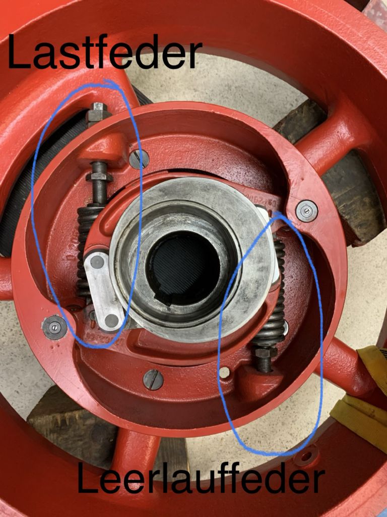
I'm glad to try and help. This is a Lanz governor showing the intermediate excentric and the two spring groups, one for idling and one for maximum speed.
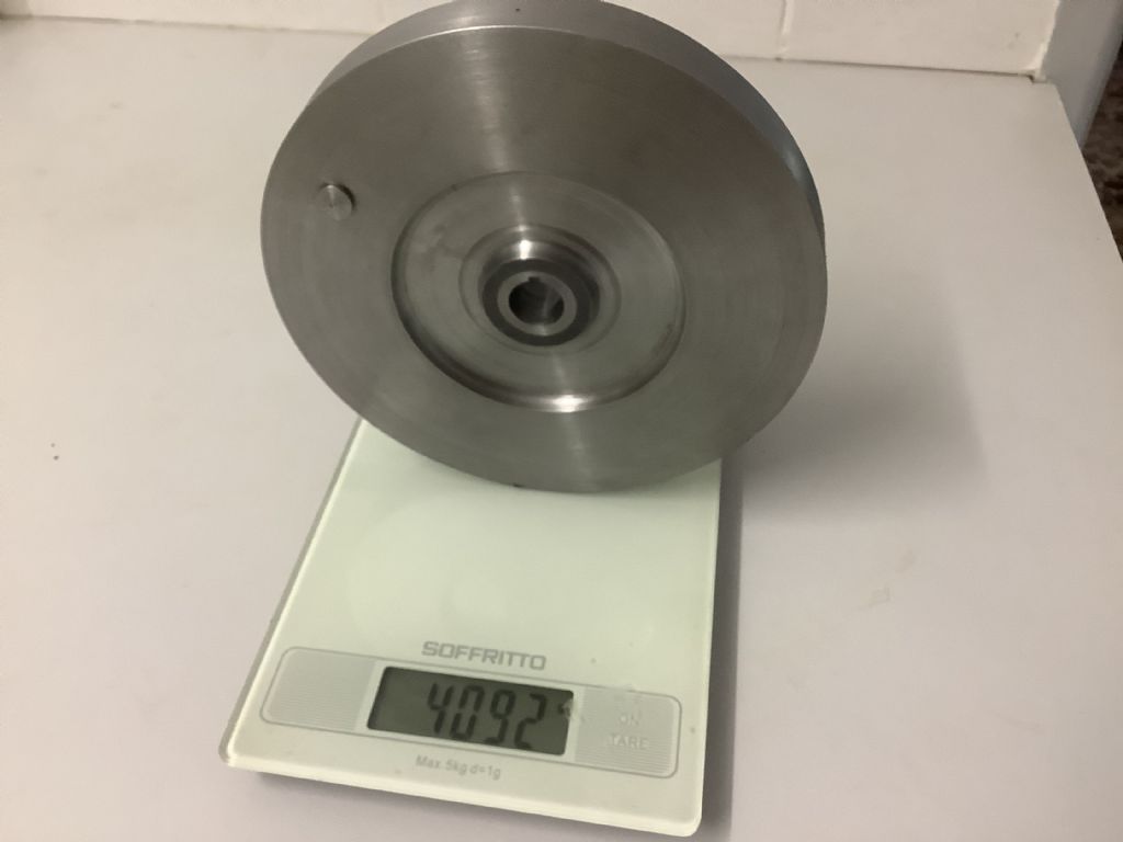
One flywheel completed and as you can see it is heavy and should give plenty of momentum to the engine and hopefully help it to run slowly. I now have to go back to the injector cam and think that through. I was pleased to hear that there is a little flexibility in the actual timing of the injected fuel. I have two drawings of the system and think that one may be a later development but as I can’t take the full size tractor apart I will have to choose the one that suits me! The one I originally designed allows the bob weights to move the eccentric via two linkage arms thus giving and advance/ retard but keeping the ‘ stroke’ constant. The fork alters the quantity of fuel to be injected but would slightly alter the timing as there is gap between contact of the ram on the eccentric and the fuel piston. The wedge shape on the Lanz avoids this. As these engines will run in the reverse direction ( more by accident than choice) does the governor advance the injection point before top dead centre? More thinking required!
A hot bulb type engine following the Akroyd Stuart design injects the fuel very early, around 150° before TDC, to allow for vaporisation. As the compression ratio increases and the engine moves towards Diesel's design the injection point moves nearer to TDC. The firing point on a hot bulb engine is more dependant on the cylinder head design than on the point of injection.
As long as the injection system is fairly symmetrical the engine will happily run in both directions. Some full size injection pump cams are deliberately asymmetrical to avoid the possibilty of starting in the wrong direction.
Thanks for the information Roger all very useful. I forgot to mention that the button on the front of the flywheel is the starting handle that springs back into the position shown when not in use.