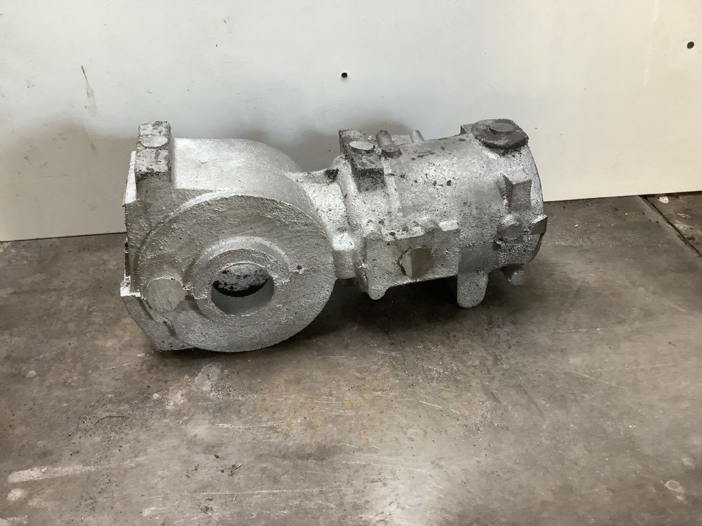
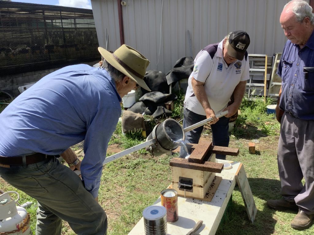
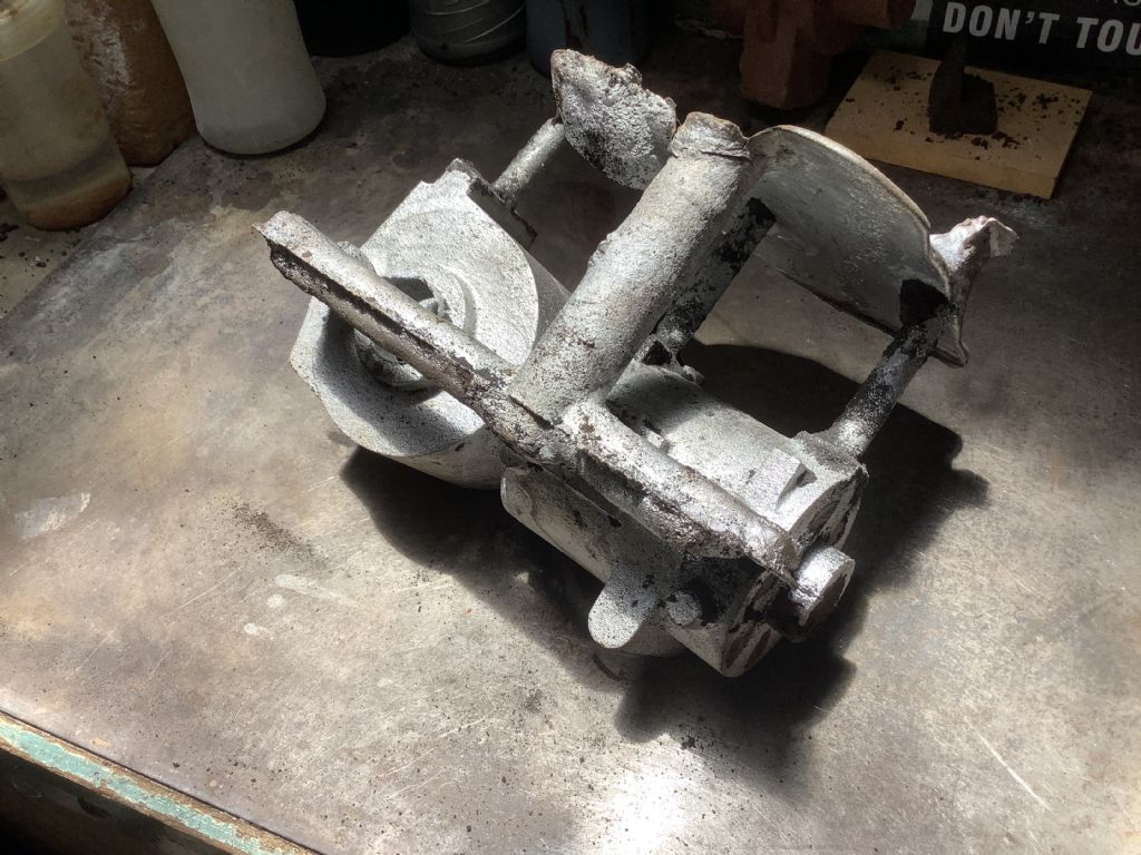
After months of work the day to cast finally arrived and even the sun was shining. I had to transport the two half flasks to my mates place in the car and the journey was taken very steadily to avoid any bits falling into the mould. On arrival the the two parts of the boxes were assembled to form one unit and made ready for the pour. With metal ( we used faulty new Diesel engine pistons) it was then poured into the mould.. I had one runner and three risers except during the pour the risers became runners and the runner became the riser due to the metal flooding the top of the flask! Oh bother – the chances of a good casting did not look good! On returning home to my workshop the flask was opened but expectations were not great. The sand was removed and the casting gradually revealed- oh what a joy to behold. There it was with no visible faults as shown in the photo with runners and risers attached and then with them removed and almost ready for machining. The other photo shows the pouring action. It will be good to start the machining but working out how to hold it is another problem. A big thanks to John,John, and Ray who helped out.
Thank you to all those who sent comments and I am pleased you enjoy following the path of the construction of this model. With regards to the weight of the pour – 4.35 Kg of metal was used in the pour of the casting and when the runners and risers were removed the weight was 3.10 Kg ( with most of the core sand removed). I do still have to remove the some sand from the water passage and that is one of the tasks for today. We had sufficient metal left in the pot to pour the spare into a couple of tin cans later to be machined into solid rods of aluminium.I am also considering casting another spare unit while I have all the casting gear set up – a glutton for punishment! This will not happen for a few weeks as I will check that the mark one is OK as I don’t want to repeat any mistakes if they have occurred in the mk1 edition.
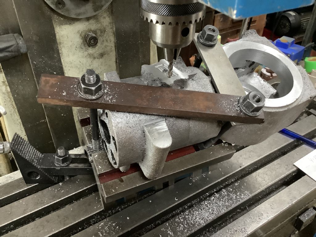
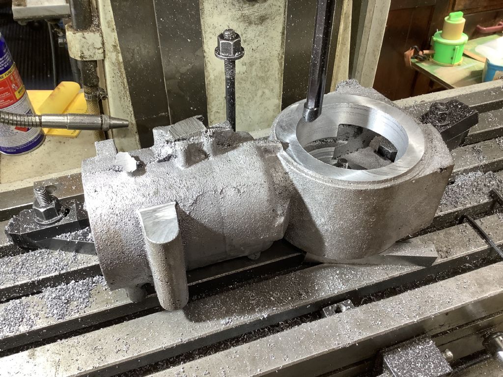
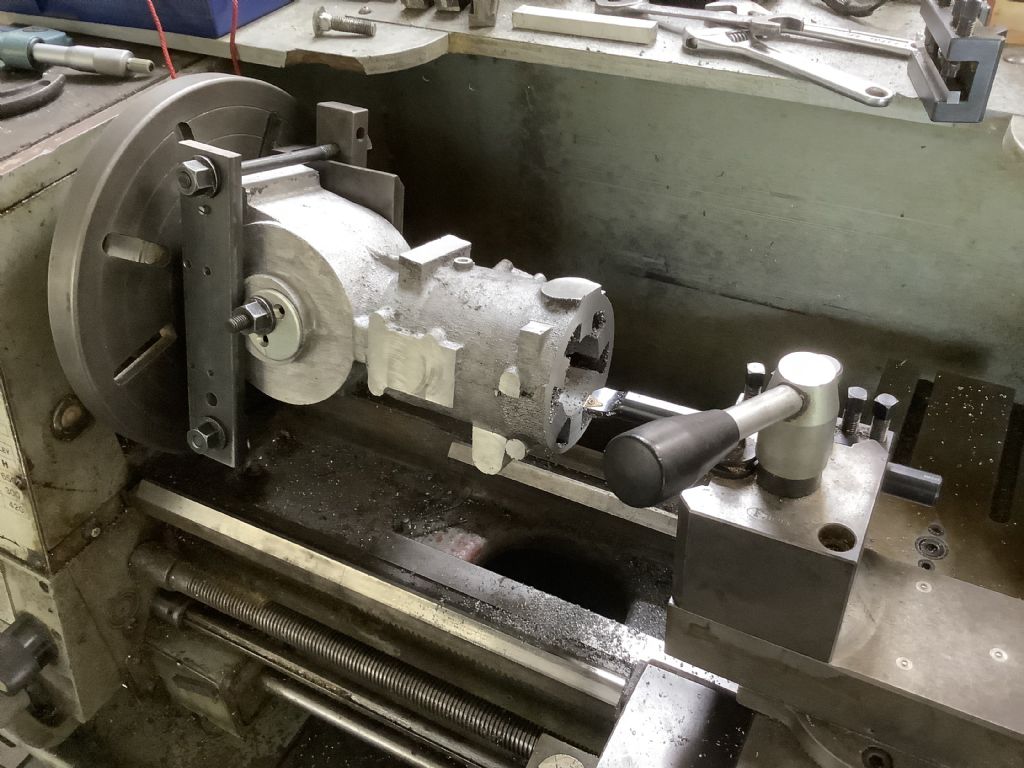
As can be seen in the photographs I have had a good day machining the casting that I made yesterday. The top photo shows the injector base block being machined flat. The second shows milling the exhaust port and the last shows the boring out the crankcase and creating a datum base to work from. Looking forward to more of the same tomorrow and it’s a change from playing sand castles!
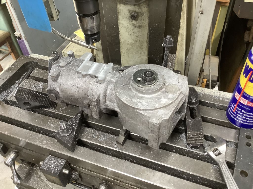
Today has proved that the engine casting can be machined with the equipment I have in the workshop but it took a long time to work out if it could actually be done. The problem is two fold, one is that its quite a large lump of material to work with and secondly it’s a rather awkward shape to hold and centre on the lathe. It does look rather precarious that far out from the head stock but it is clamped by a long bolt through the crankcase and a clamp across the top. The speed was kept low and the boring process was just that! Each pass took ages but I couldn’t risk a higher speed. I will be making another casting as there are parts that I feel need to be changed or checked. The school report would say” 7/10 can do better”. The main problem is the centring of the core as on this example it had dropped a few mm off the centre line, also part of the water passage needs to be rotated 30 degrees so that the head bolts have material for the studs to be fitted and the injector has an unobstructed position in the head. The second problem is easy to solve as I just have to glue the two halves the correct way as they were designed! This casting will not be wasted as it can be the basis of another model but not on this tractor.Yes, today was a big learning curve and it will make next time easier as I now know it can be done and how to do it, just put it down to the acquisition of yet more experience!
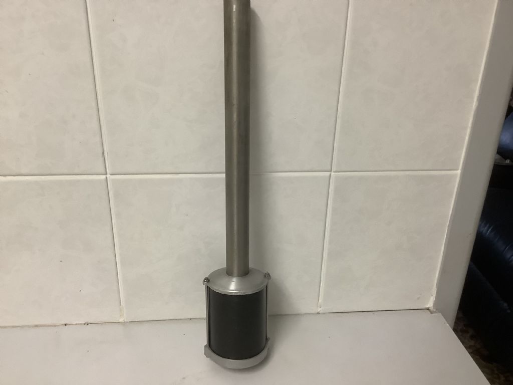
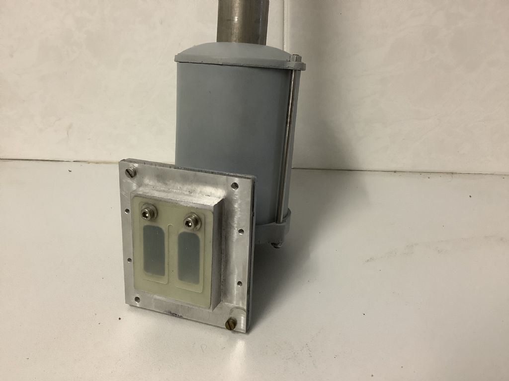
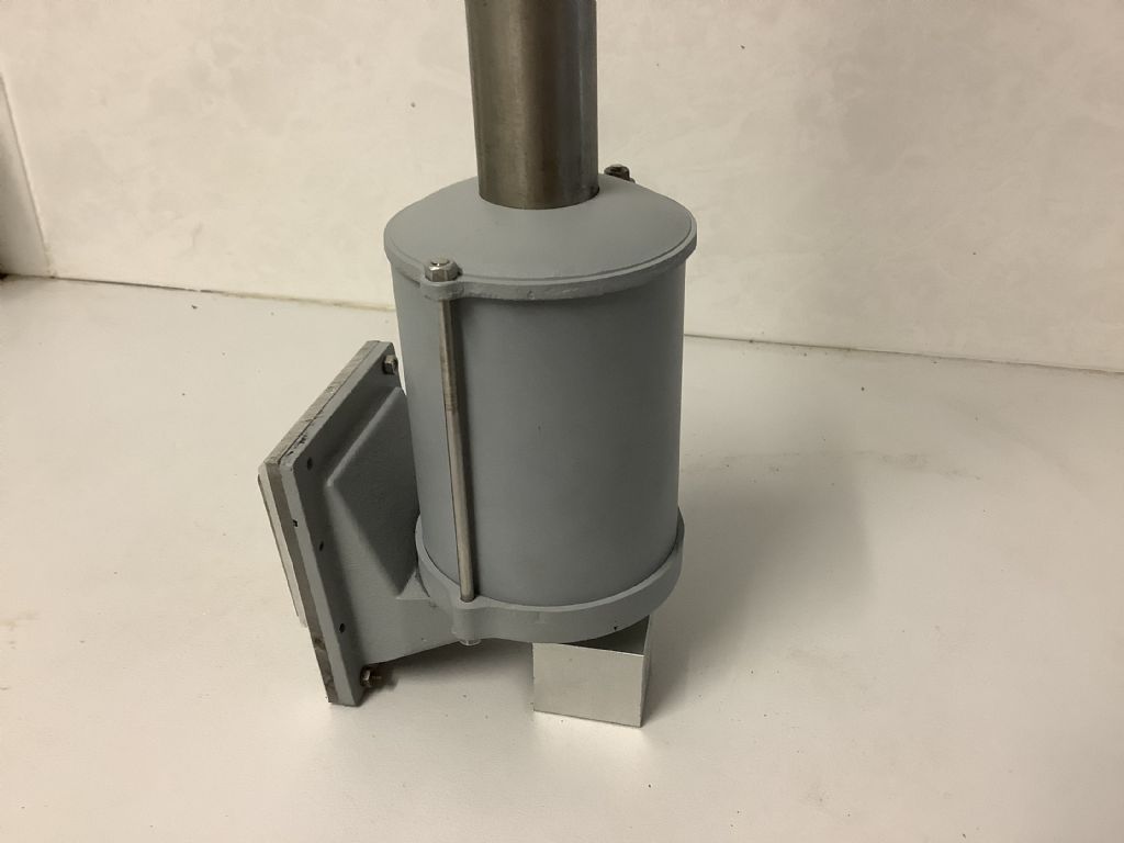
No this is not a pot belly heating stove but the air filter and intake pipe for the tractor. I have yet to make the casting that connects it to the back of the engine and reed intake block. The top and bottom are aluminium castings and the side is rolled steel sheet. I have decided to make a new crankcase casting as there are areas “ in need of improvement “! I am in the process of a redesign of the internal core and that means more 3D printing and I have to work that in with the weather as we are in storm season and I do not want any equipment damaged by lighten strikes or stop half way through a 15 hr pint! While the printer is busy I will be designing other small parts and reading about hot bulb engines. There is always plenty to think about and do.
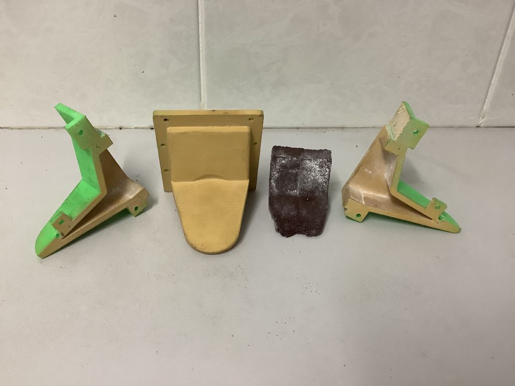
This week I have made and machined the three castings for the air intake system.The photographs show the core box, pattern and core, and then two views of the completed reed valve air filter system. The other night we had 120 mm of rain in 12 hours together with thunder and lightening but fortunately it has cleared away out to sea and this means the 3D printer is now back in action printing the the revised core box for the crank case. Each of the four parts takes about 14 hours and by the end of today I will have printed part one! It looks as though I will be ready to cast the crankcase again next week ,weather permitting. T
Fred.
While every thing is ready for a casting session the weather has postponed any progress for some time as last night we had 200mm of rain. In the last week we have had 325mm and every thing is very soggy!
Unfortunately I can’t report any progress on the tractor due rain stopping progress with the main casting. In November we had 600 mm and this afternoon we had 25mm in 15 minutes! As we have a metal roof on both the house and the shed the din was unbelievable.I have made some progress with the drawings but until the main engine casting made and machined practical progress will be slow.
Gred
To those who have been reading about the construction of this McDonald tractor I will be resuming this construction in early 2022. I would like to take the opportunity to wish you all a safe and happy Christmas and may 2022 bring more time in workshop enjoying our great hobby.
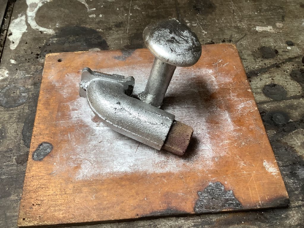
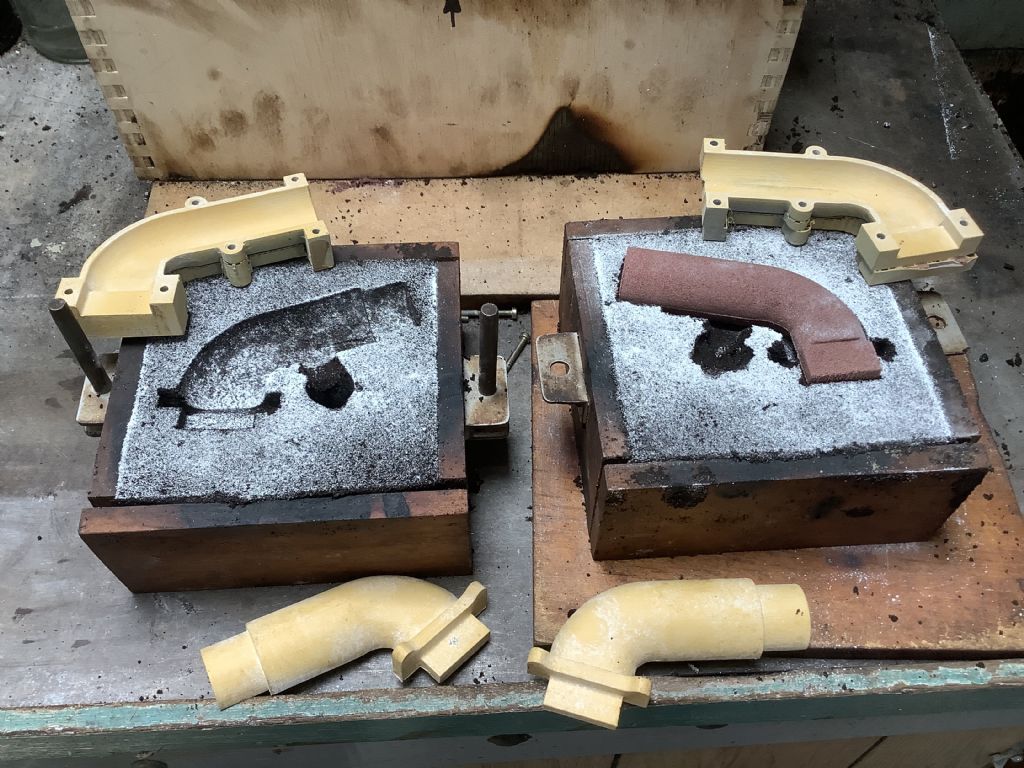
2022 is here and may it better than 2021. The dreaded new plague is spreading fast and the best place to be is to hibernate in the shed. Having had a short break from the tractor I am now ready to recommence and press on. I have completed all the drawings for the quite complicated clutch mechanism and made progress this week with the exhaust manifold. The pattern and core box for both of these items were 3D printed. The shape transitions from the port to the pipe and it was great to see how Fusion 360 and printer perform this process. The photographs show the end result ( sorry about the double up – not sure what happened as I wrote the words, added the pictures but only the pictures were sent). Weather here is hot (32C) and there is a cyclone hanging of the coast!