Mc Donald Model tractor

Advert

Mc Donald Model tractor

Home Forums Work In Progress and completed items Mc Donald Model tractor

Viewing 25 posts - 151 through 175 (of 359 total)
  • Author
    Posts
  • #557228
    Four stroke Fred
    Participant
      @fourstrokefred

      fde3d0c5-d1a8-4243-a463-eaf8ca34ee25.jpeg

      Advert
      #558554
      Four stroke Fred
      Participant
        @fourstrokefred

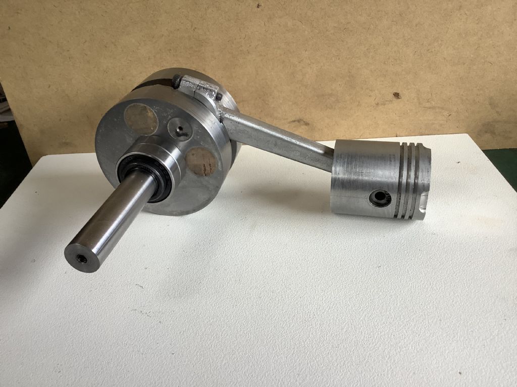
        Over the last couple of weeks I have been refining the patterns and core boxes for the engine. While the 3D printer has been working overtime I have also been making the crankshaft. The crank disc are made from 20mm thick mild steel plate. The oversized blanks were a donation from the local laser cutter and had been cut to form holes in some one else’s work and as a result each had a “ start cut” abut 6mm in from the outer edge. By offsetting each disc in a four jaw chuck I was able to machine up two 82mm blanks which after cleaning up were soft soldered together and the machined to the 80mm size required.The two discs ,now soldered together ,were marked out for the crank pin and crankshaft holes and bored on the lathe using a four jaw chuck as a means of holding the work. Photographs of the finished crankshaft to follow later. The crankcase/ cylinder casting has caused much thinking and screen time and has taken longer than anticipated but it will be made!
        Fred.

        #558568
        SillyOldDuffer
        Moderator
          @sillyoldduffer

          Super work Fred, please keep it coming. Out of my league – I'm following progress in stunned silence!

          smiley

          Dave

          #558596
          Four stroke Fred
          Participant
            @fourstrokefred

            From one silly old duffer to another thanks for the comments. It appears that progress has slowed down but all the work completed so far has been the type of work that I have experienced before but this engine is a real brain scratcher. It’s trying to fit all the internals into the scale outside shape and above all to have it working and producing a reasonably characteristic sound. This type of engine is new to me and really stretches my capabilities, experience and equipment and even after all the planning there is no guarantee it will work! It’s the challenge and vision of the finished tractor that keeps me going.

            Fred.

            #559590
            Four stroke Fred
            Participant
              @fourstrokefred

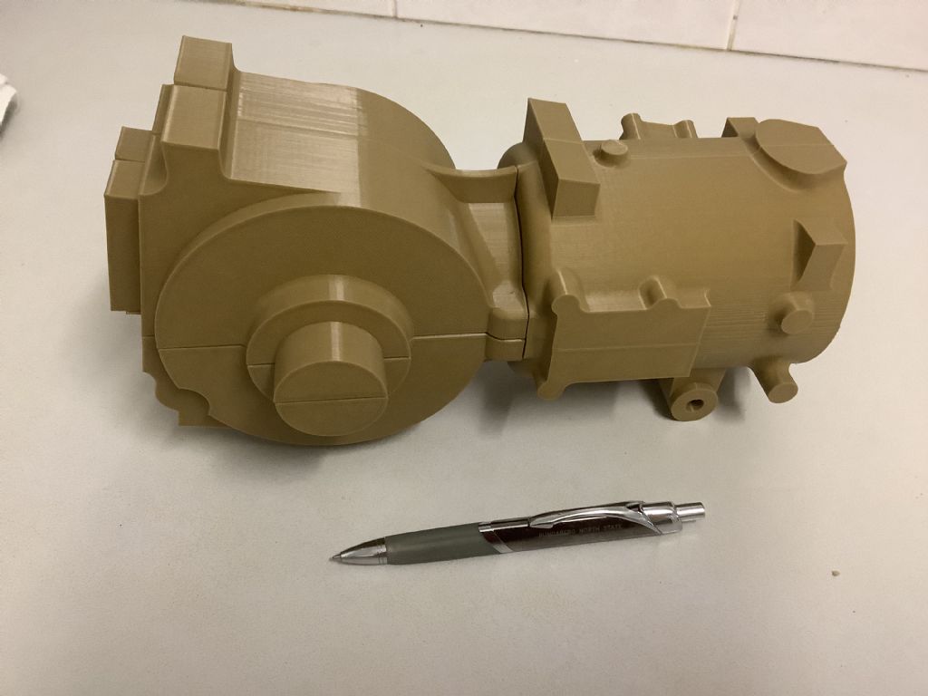
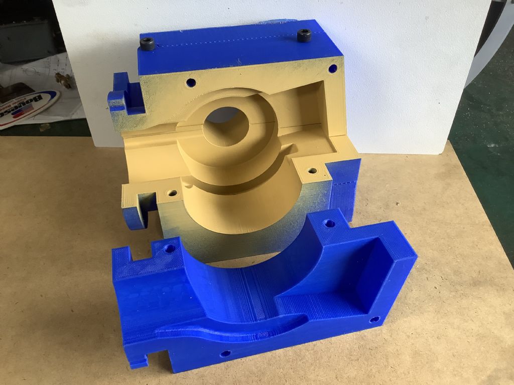
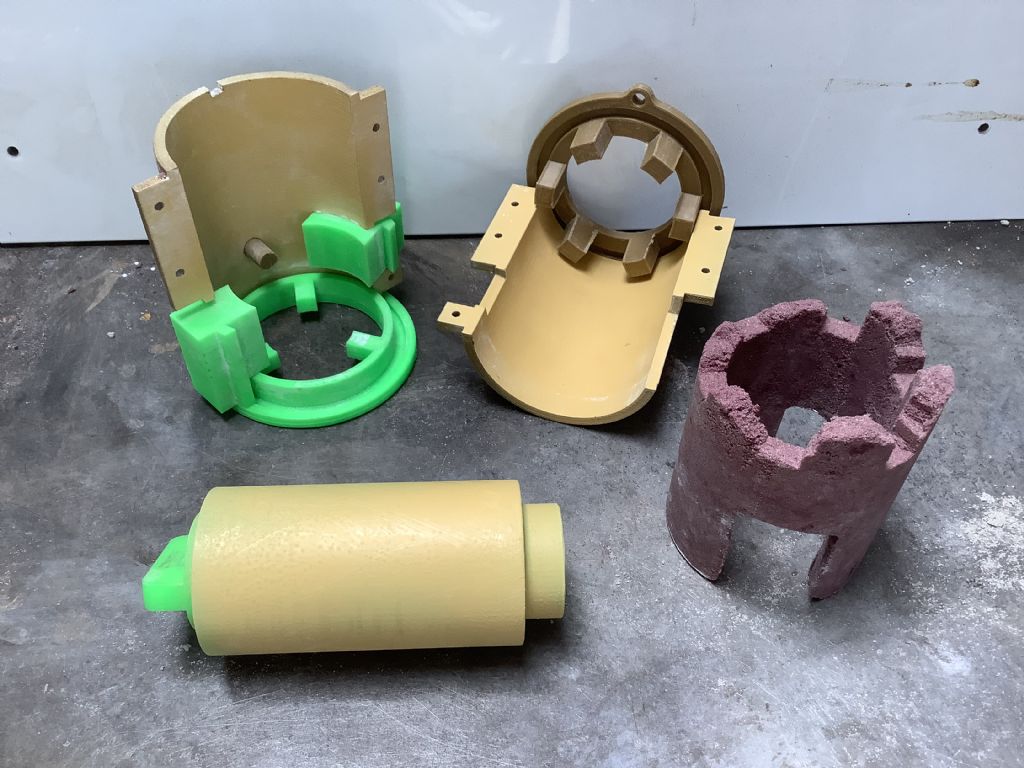
              The top photo shows the parts of the 3D printed core box for the crankcase. The top part is in two pieces but the bottom is one piece and took 34 hours to print. I still have to print the cylinder core boxes and then check that it all fits together and can be cast. During the ,day while the printer was working ,I machined up the the crankshaft from blank mild steel discs and 4140 steel shafts. I still have to machine the second shaft of the crankshaft – this is the one that has the clutch and drive attached to it and the design is still being finalised. The crank is carried on four ball races to spread the load and give stability and has oil seals on the outside as the crankcase is a pressure chamber on a two stroke engine. The crankshaft has been balanced in the same way as described in the Edgar Westbury book on engine design and manufacture ,a book that I value and purchased in Bristol in 1962.The drilled balance holes have been filled with cork to keep the volume as high as possible.

              Fred.
              da5b4773-8ac0-4ae5-bcab-472a9960ab22.jpeg68632d46-909f-44d6-87df-3c71e6eee3e4.jpeg

              #560798
              Four stroke Fred
              Participant
                @fourstrokefred

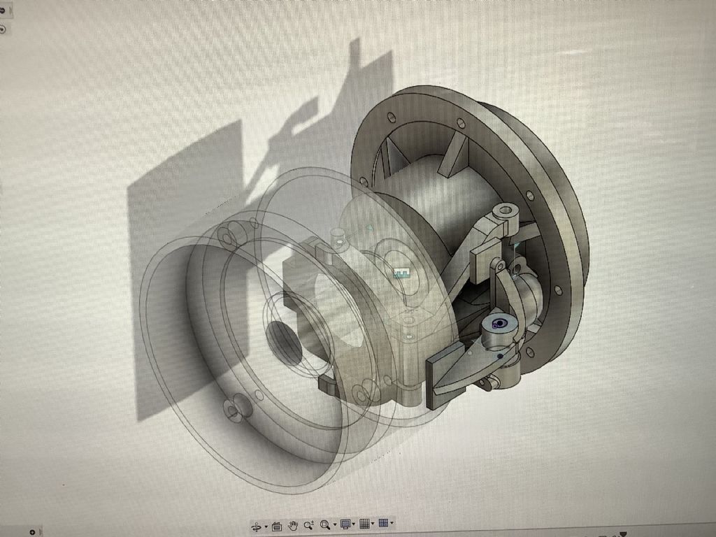
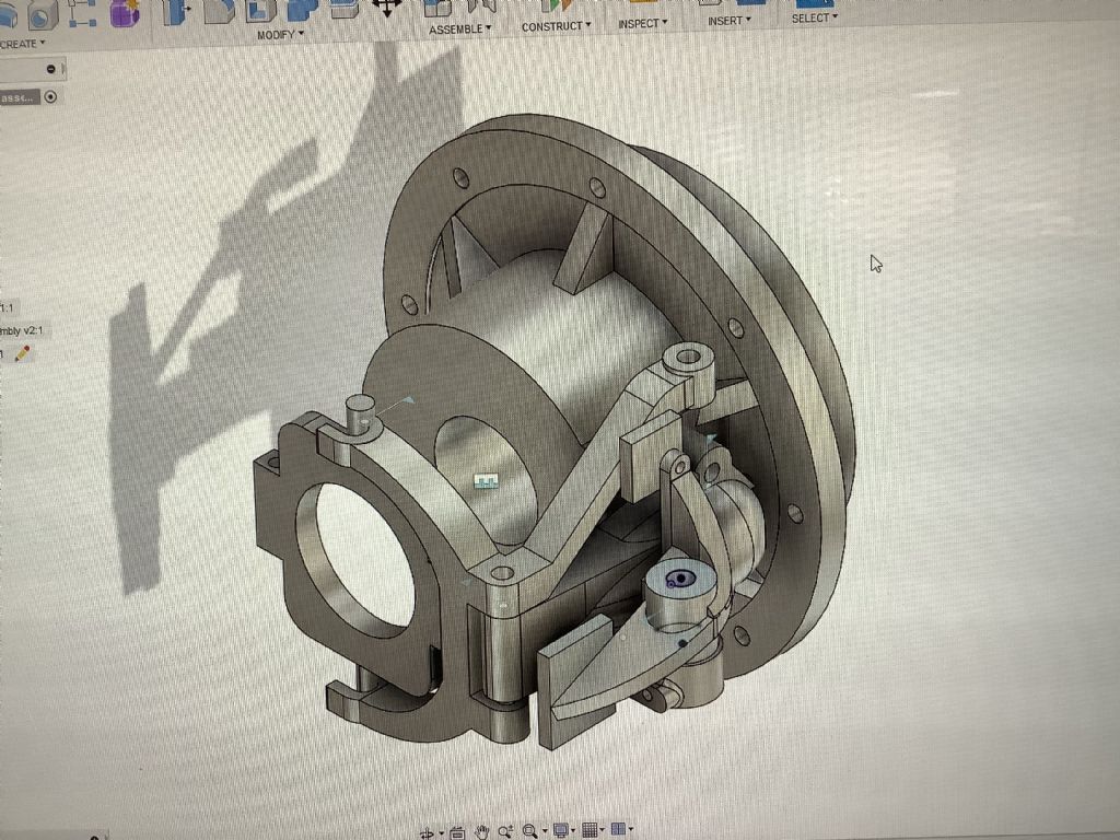
                d5d96d7f-d436-4cf4-a697-06c613c5f3a1.jpega3d2a9e0-c488-43d4-b7d9-c2caab6bb6cf.jpegWork continues on the development and 3D printing of the core boxes for the cylinder/ crankcase unit. Before this part is cast I need to make sure that I have provided all the lugs and attachment point for the various parts that help to make this tractor engine work. The photographs show the CAD drawing / assembly ( complete with strobe effect) of the clutch and brake assembly. The second photo shows the thrust collar that forces the clutch plates together. On this tractor the clutch lever also applies the brake pad to the outer face of the pulley after it has disengaged the single plate clutch. This is the only brake on the tractor but later editions had an extended shaft from the gearbox and this shaft carried a drum and band brake assembly with the brake being applied by a lever. These parts have yet to be made in metal and will probably be prototyped with the help of the 3D printer to check that all is well.

                Fred

                #560830
                Adrian R2
                Participant
                  @adrianr2

                  So it does have a brake after all. That makes a bit more sense than relying on the operator always having to find somewhere flat to stop. Does the lever have a means of holding it in the brake position?

                  I suppose the next question is how is it started, both in real life and model form? I found one video on Youtube that appears to show heating the hot bulb and then inserting a peg into a hole in the flywheel to turn it over.

                  #561152
                  Four stroke Fred
                  Participant
                    @fourstrokefred

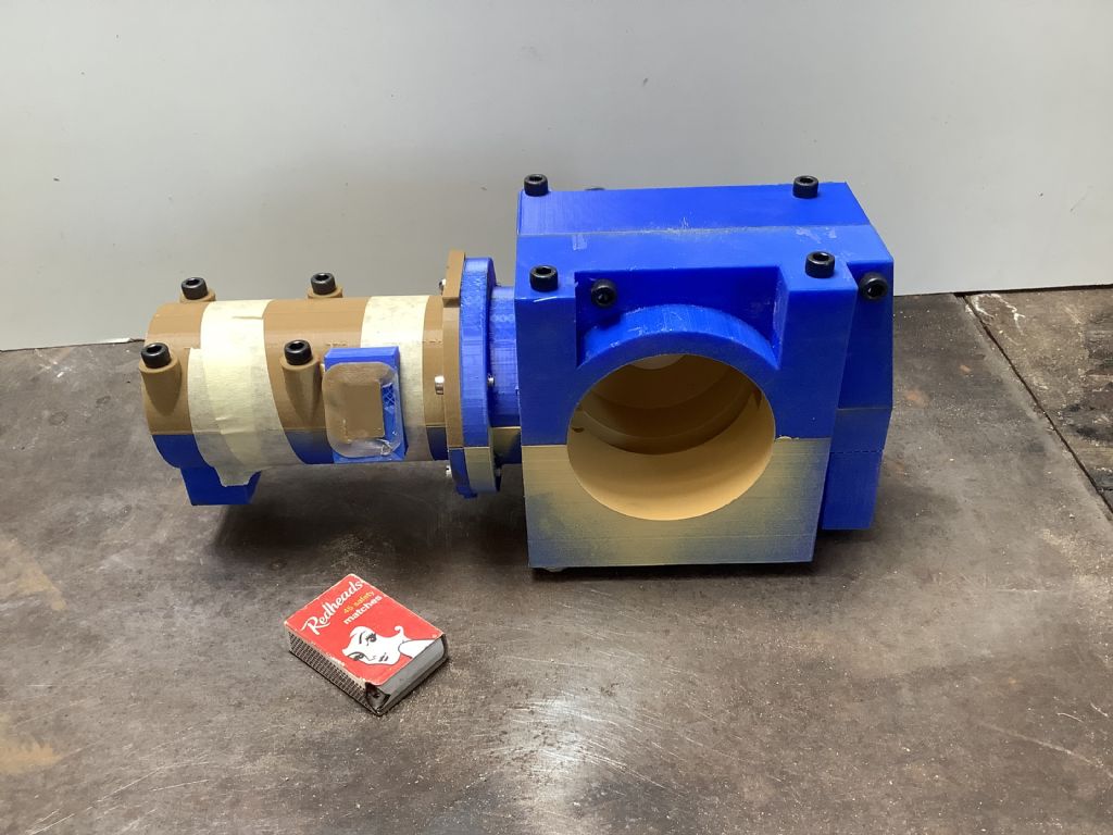
                    ebc73fe6-ef83-48bb-ac7e-7ef249f18b89.jpegThis is the assembled core box for the inside of the tractor engine with a match box for size comparison. For those not into casting this box makes the sand shape that makes the inside of the engine hollow. I still have to 3D print the core box for the water passage and hope to finish that later today or tomorrow. With reference to the “braking system” I am sure the brake will only slow down the engine via the pulley as when the lever engages the brake it disengages the clutch and as this is connected to the gearbox no braking of the tractor is applied. I will check this out next time when I visit the tractor and owner.

                    Fred

                    #561155
                    Four stroke Fred
                    Participant
                      @fourstrokefred

                      I have checked in the owners hand book for this tractor and can now see that the brake does slow the machine down as the pulley is connected to the gearbox by the chain and sprockets. As long as the tractor is in gear the application of the brake pad to the pulley and disengagement of the clutch should slow progress!

                      Fred.

                      #561583
                      Adrian R2
                      Participant
                        @adrianr2

                        I would guess (by extrapolation from my uncle's Field Marshall) that on the full size one just reducing the throttle to minimum would slow the whole contraption down to quite close to a standstill, then the final declutch and push the lever further to bring to a halt with the transmission brake if needed – on the soft it'll probably dig in anyway, but hard packed ground or a slope might be tricky. Stop engine and release clutch as a parking brake. Actually much the same as a single pedal ride on lawnmower nowadays thinking about it.

                        Thanks for the scaling factor – on several of your pictures it's not obvious what size the parts are which is a compliment to your work.

                        #562983
                        Four stroke Fred
                        Participant
                          @fourstrokefred

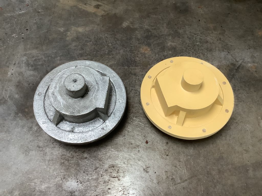
                          91073f99-870a-41da-b090-dc57af1c7d34.jpegBack in action after a short holiday and this is the result of today’s efforts. This casting (and pattern) is for the engine drive side bearing and has the clutch/ brake mechanism attached to the flat area on the side. This is a prelude to attempting the main casting in the not to distant future , something that I am bit apprehensive about ! I have spent quite some time on the designing of the mechanisms relating to the clutch and injector cam as these are attached to the crankcase/ shaft and I want to make sure all is well before casting the crankcase.

                          Fred

                          #562984
                          Four stroke Fred
                          Participant
                            @fourstrokefred

                            91073f99-870a-41da-b090-dc57af1c7d34.jpegBack in action after a short holiday and this is the result of today’s efforts. This casting (and pattern) is for the engine drive side bearing and has the clutch/ brake mechanism attached to the flat area on the side. This is a prelude to attempting the main casting in the not to distant future , something that I am bit apprehensive about ! I have spent quite some time on the designing of the mechanisms relating to the clutch and injector cam as these are attached to the crankcase/ shaft and I want to make sure all is well before casting the crankcase.

                            Fred

                            #563269
                            Four stroke Fred
                            Participant
                              @fourstrokefred

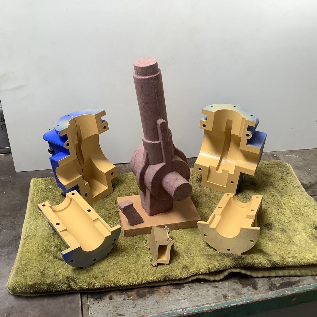
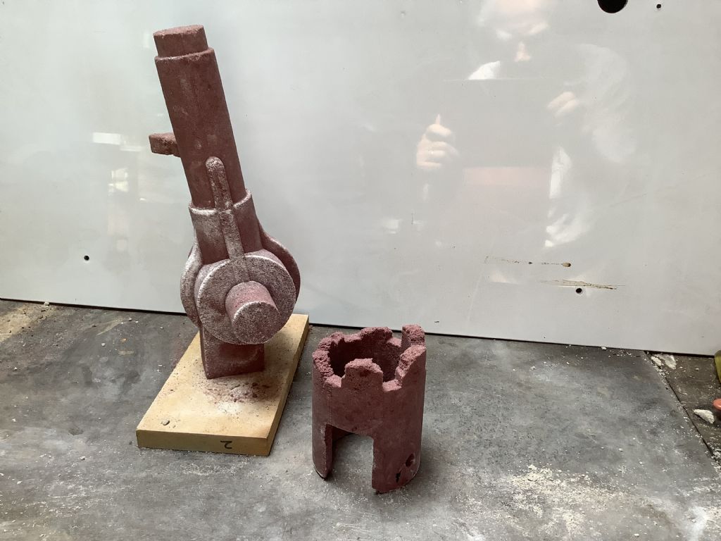
                              4b3ea678-8aca-43eb-9927-2479fa21de0c.jpegThis weird and wonderful sand castle is the core ( and core box) for the inside of the engine.The small shape near the front left on the board is the core for the exhaust port and will be later will be added on assembly to the main body. As can be seen the 3D printer has been working overtime to produce the core boxes. It has taken many hours so far and it is quite gratifying to see this shape appear from the compound boxes. A liberal coating of silicone spray may have helped. This attempt is not perfect and I think I will have another go as I feel I can improve the packing of the sand in one area and it will be good to have a spare. I still have the more difficult water jacket core to make but feel spurred on by this effort.
                              Fred

                              #564296
                              Four stroke Fred
                              Participant
                                @fourstrokefred

                                This picture shows the results of some experimentation with the core for the water passage and proves that not every experiment is a success as the sand was not packed into the castellated sections tight enough Packing the core box in its present form proves a problem and a rethink is required to make sure the sand can be packed into all the recessed parts. This core has to fit over the core in the background and makes the space for the water to circulate around the cylinder. I may opt to make the core as two seperate pieces and glue them together but this will entail more 3D printing. While the printer is doing it job it gives me time to continue the design work on the injector pump and also the clutch unit – not much to show but work that has to be done.

                                Fred.

                                c5734d80-4d17-4ae6-8399-76c586738b55.jpeg

                                #564298
                                Four stroke Fred
                                Participant
                                  @fourstrokefred

                                  This is the core core box in its present form.

                                  Fred.3b29b01c-2cf6-4b05-bf7f-019399787efe.jpeg

                                  #564554
                                  Four stroke Fred
                                  Participant
                                    @fourstrokefred

                                    This is the first half of the revised core and box for the water chamber and shows the castellated top. This leaves space for the water and the parts in between are for the cylinder head stud location. This was the easier half to make and the challenge is now to make the second half with all the ports spaces and supports.

                                    Fred

                                    e270f931-de2b-414e-aa3f-9fdd580b3663.jpeg

                                    #565275
                                    Four stroke Fred
                                    Participant
                                      @fourstrokefred

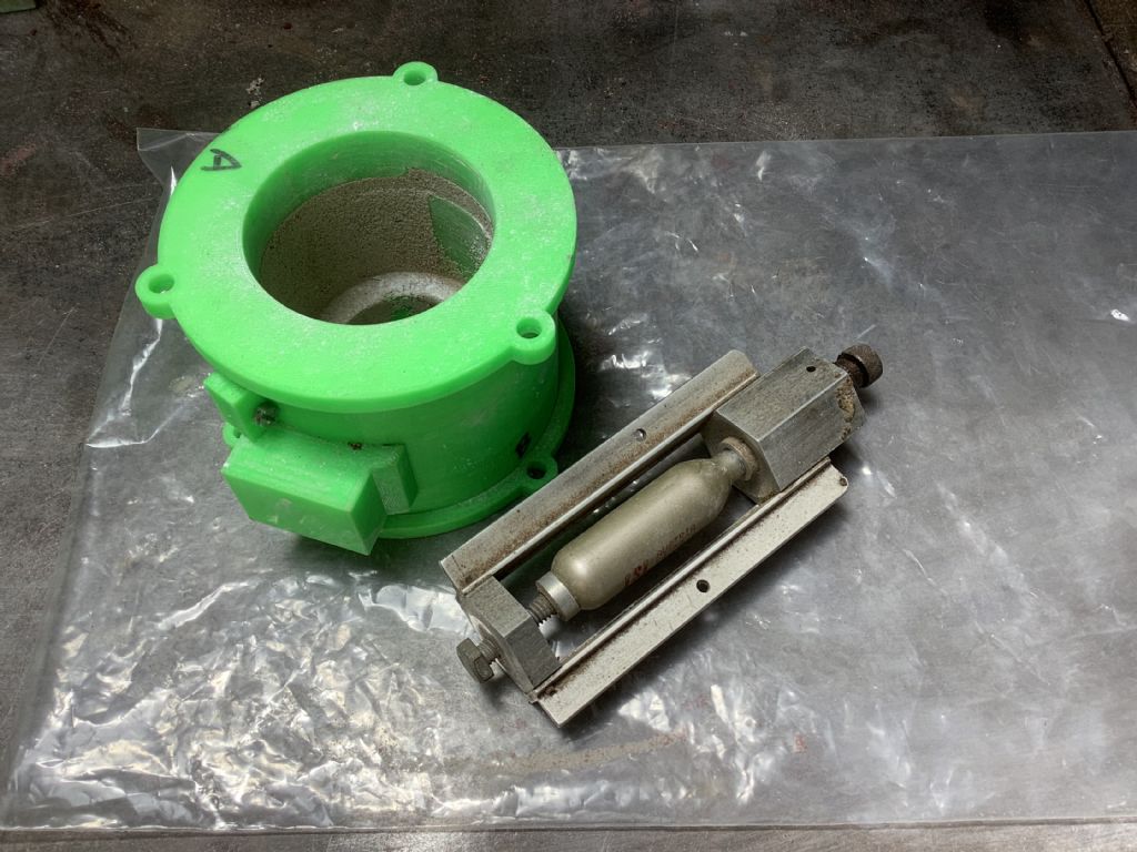
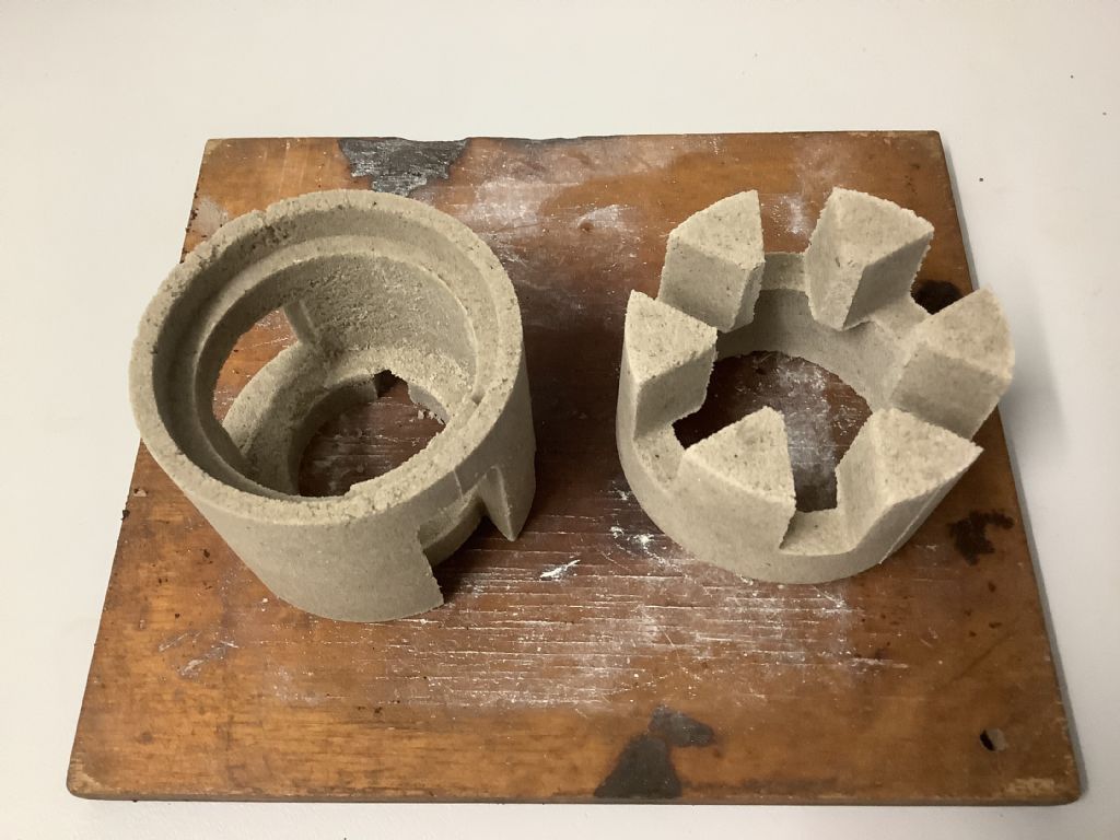
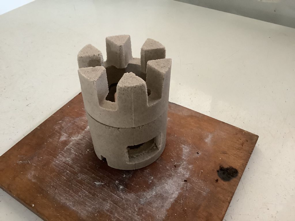
                                      Development continues with the core for the water passage. I have tried to make this core using the resin sand but due to the complicated nature of the beast time runs out and the mixture hardens before I have a chance of finishing the packing. I am now trying the CO2 process as this gives me more time. The picture shows the packed core box, the plastic bag in which the core box is placed and then the CO2 is added in the form of the Sparklet cylinder and jig. The whole unit is then sealed up and the bag inflates with the CO2 and it is left to harden up. The first time I did this I hadn’t made the mixture strong enough and parts crumbled and so the experiments continue with the hope that I will succeed in the end. The changes in the colour of 3D printed core Cox is a result of continued modifications.

                                      #565276
                                      Four stroke Fred
                                      Participant
                                        @fourstrokefred

                                        2590dae3-ccff-42bd-800f-8a036c8aa1fc.jpeg

                                        #565460
                                        Four stroke Fred
                                        Participant
                                          @fourstrokefred

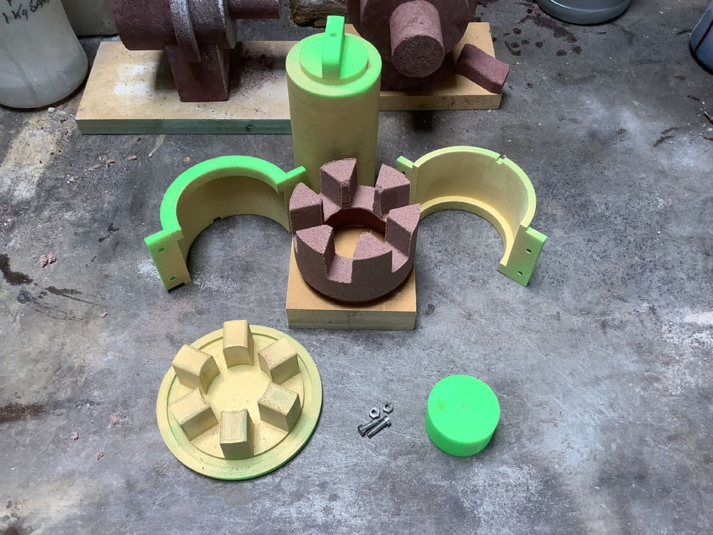
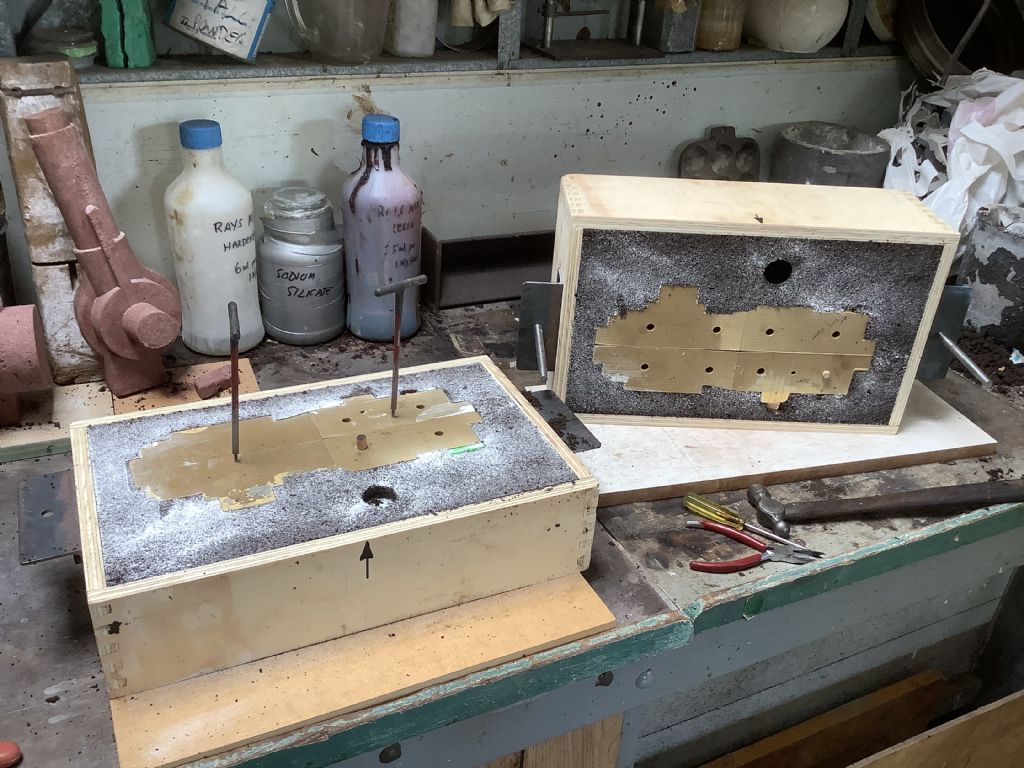
                                          After many attempts and a big learning curve success has arrived at last! After the modifying, painting and polishing of the core boxes I packed them with sand mixed with sodium silicate. The packing is not easy as it has to carried out in a certain order but at least with the CO2 method it gives me time before it is placed in the plastic bag to be gassed. After experimenting I discovered that half a kg of sand and two table spoons of sodium silicate seem to work well. There are sections of this core that are quite thin and also as the sand is fine it does need a strong mix to bind it all together. As the saying goes “ Small things make perfection but perfection is no small thing”. These cores may not be perfect but I am quite pleased with the results so far. The two halves will be glued together and then placed over the main engine core to create the water passage of this engine. The photographs show the two halves and then the dry assembly.

                                          Fred

                                          #565461
                                          Four stroke Fred
                                          Participant
                                            @fourstrokefred

                                            92e5b7bc-e98c-4dd3-a84d-5dbf4b7e4ef2.jpegc317c6ef-a8fa-4882-a608-8c6096b160fe.jpeg

                                            #565462
                                            Jon Lawes
                                            Participant
                                              @jonlawes51698

                                              I'll enjoy your success by proxy; there is nothing quite like the feeling when it all comes together!

                                              Fantastic work.

                                              #565467
                                              Michael Gilligan
                                              Participant
                                                @michaelgilligan61133

                                                I remain in awe of what you are doing, Fred

                                                … What a superb project !

                                                MichaelG.

                                                #565896
                                                Four stroke Fred
                                                Participant
                                                  @fourstrokefred

                                                  389862d4-db6e-4f99-b041-d92f29dff672.jpeg4bdbdc17-fb35-4f50-b23d-ac6f5d9a883a.jpeg76576ced-499e-4c31-9fab-828c4367e915.jpeg

                                                  #565900
                                                  Four stroke Fred
                                                  Participant
                                                    @fourstrokefred

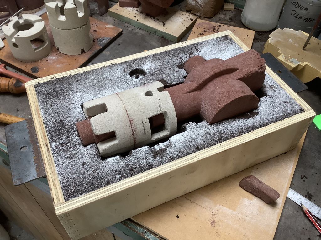
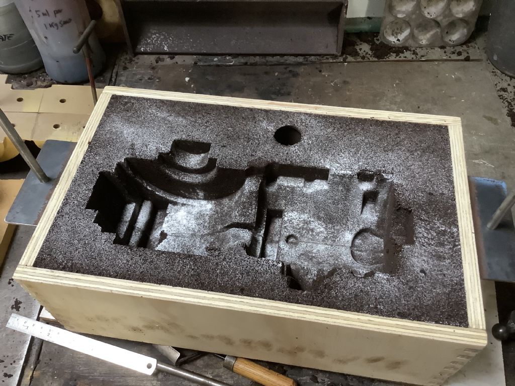
                                                    Today I made the boxes for casting and then did a trial run to check to see if all the parts would fit together. The patterns came out quite well but there were a couple of places where there was a slight overhang (that I had omitted to see) and the sand pulled out. Modifications to both the pattern and by making small changes to the core box should over come these faults. I will repack the boxes and then cut the runners where the metal flows in and risers that allow gasses to escape and act as a reserve of metal when the casting cools and shrinks.

                                                    Fred.

                                                    #567854
                                                    Four stroke Fred
                                                    Participant
                                                      @fourstrokefred

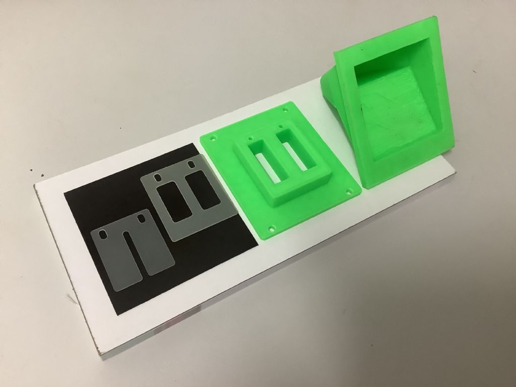
                                                      These are the 3D prints of parts of the air intake system showing the housing for the reed valve in the centre, the support for the air intake manifold on the right and the reed valves on the left. All the green parts will be made in aluminium and bolted to the crankcase of the engine. The reed valves where donated to me by our local motorcycle dealer after he had made a visit to the workshop and viewed the progress on the tractor. As the lager castings are poured outside we will have to wait for the weather to clear up before the crankcase can be cast but hopefully some time next week. This last week has seen hail 160mm in dia fall at Mackay, north of us – the storm season has arrived with vengeance !

                                                      Fredf2e6511b-2729-42b2-ab94-68418bf1df6b.jpeg

                                                    Viewing 25 posts - 151 through 175 (of 359 total)
                                                    • Please log in to reply to this topic. Registering is free and easy using the links on the menu at the top of this page.

                                                    Advert

                                                    Latest Replies

                                                    Viewing 25 topics - 1 through 25 (of 25 total)
                                                    Viewing 25 topics - 1 through 25 (of 25 total)

                                                    View full reply list.

                                                    Advert

                                                    Newsletter Sign-up