Mc Donald Model tractor

Advert

Mc Donald Model tractor

Home Forums Work In Progress and completed items Mc Donald Model tractor

Viewing 25 posts - 26 through 50 (of 359 total)
  • Author
    Posts
  • #496448
    Four stroke Fred
    Participant
      @fourstrokefred

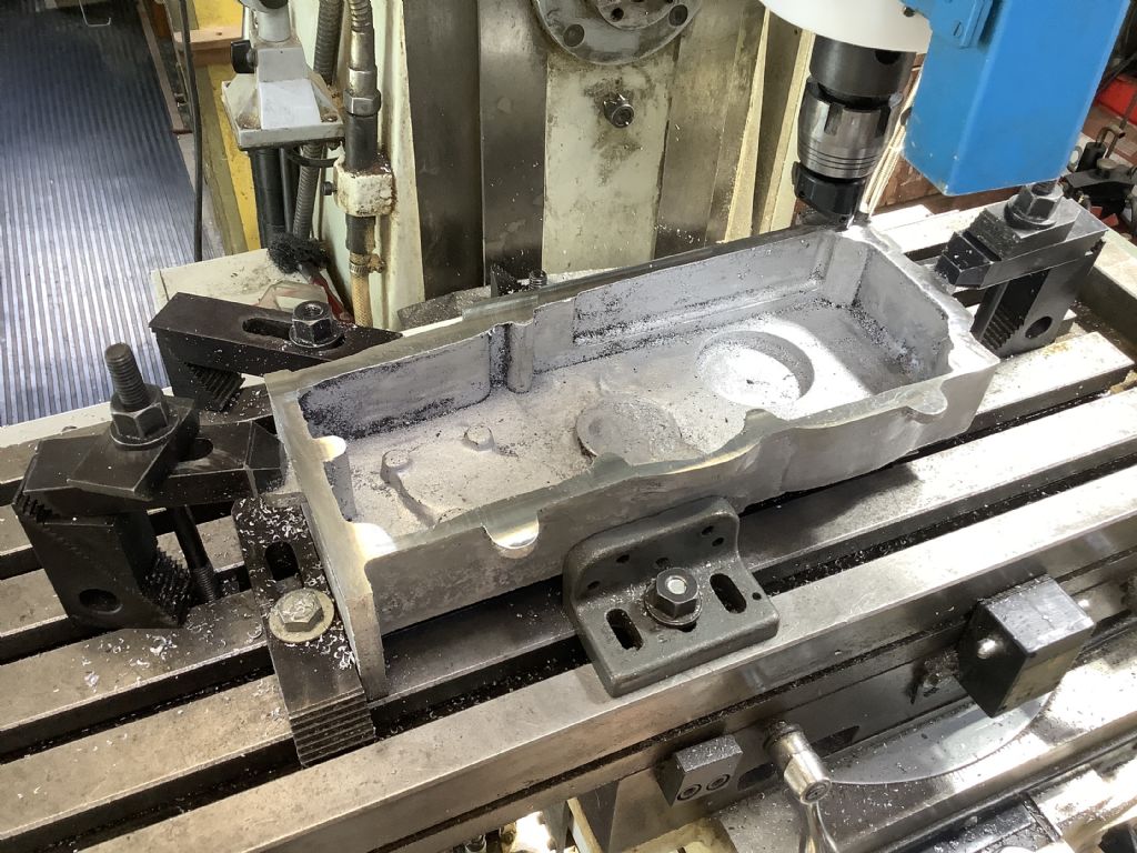
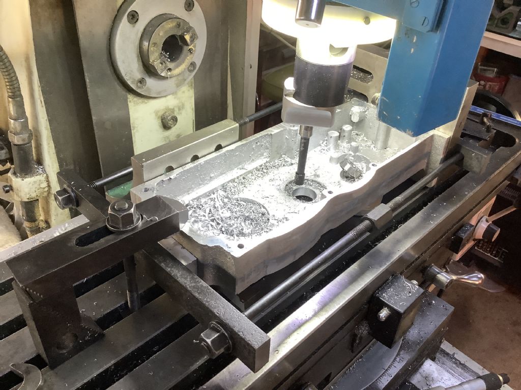
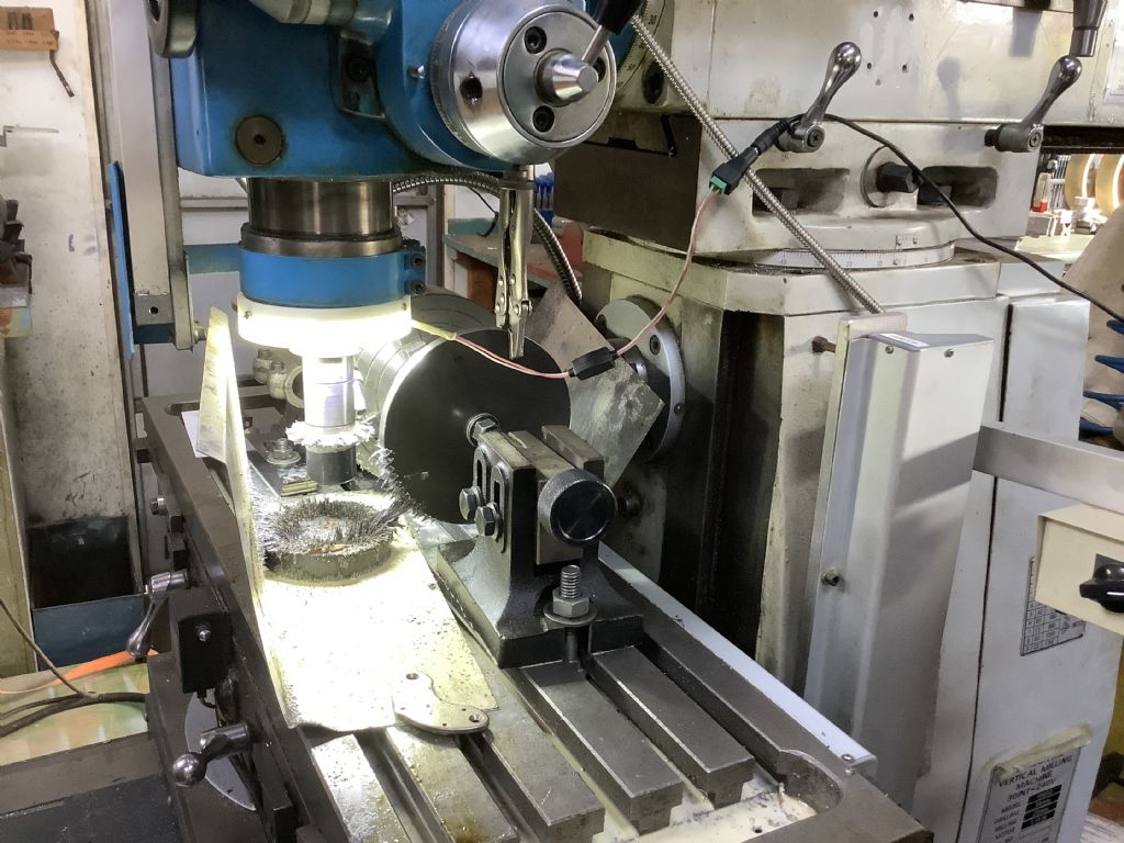
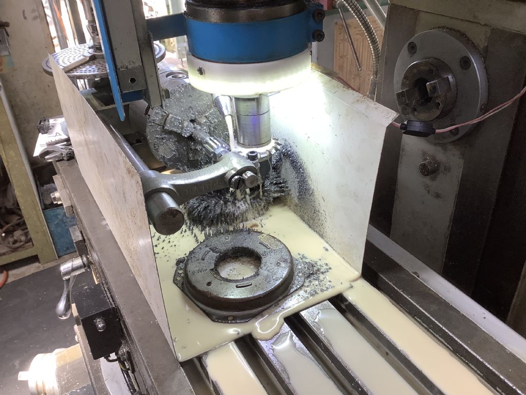
      The weather last week allowed casting to take place in the open air foundry and this time there were no unwanted holes in the casting of the first half of the gearbox. The photo shows the casting in the milling machine having the faces cleaned up. The lugs on the side are for holding purposes only and will be later machined off. I hope to cast the second half next week.
      Fred.a29b83e2-1e25-465f-a016-ec2e426bbe96.jpeg

      Advert
      #496449
      Four stroke Fred
      Participant
        @fourstrokefred

        The weather last week allowed casting to take place in the open air foundry and this time there were no unwanted holes in the casting of the first half of the gearbox. The photo shows the casting in the milling machine having the faces cleaned up. The lugs on the side are for holding purposes only and will be later machined off. I hope to cast the second half next week.
        Fred.a29b83e2-1e25-465f-a016-ec2e426bbe96.jpeg

        #499828
        Four stroke Fred
        Participant
          @fourstrokefred

          3c0a190e-786a-46d9-a6cb-9f9212b0f038.jpeg24c3edbe-1a68-44af-ab4e-ee26a7bb7c52.jpeg

          #499833
          Four stroke Fred
          Participant
            @fourstrokefred

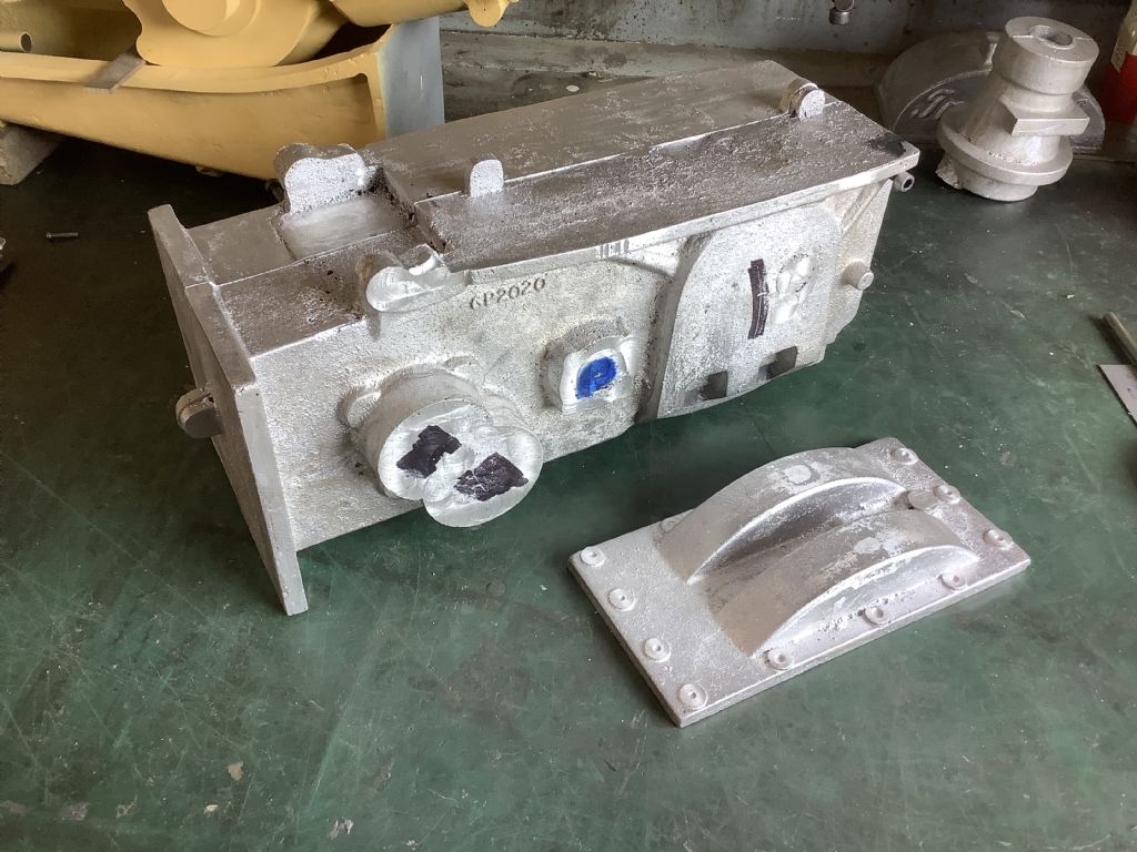
            The photographs show the two parts of the gearbox casting bolted together and the set up for the boring of the ball race position for the differential shaft. The model suddenly seems to take on volume and has now become quite a big lump of material to man handle and set up on the mailing machine. Next step is to machine the gears that make up the differential and rear wheel drive. It will be a case of shut the shed door and concentrate on the job in hand.

            #499847
            Adrian R2
            Participant
              @adrianr2

              I'm trying to imagine the gear setup here – presumably the two black marked bosses at the front are cross shafts for the actual gear change, then the blue one is an idler and the differential goes under one of the humps? If so what's the second, a transmission brake perhaps?

              #499851
              Four stroke Fred
              Participant
                @fourstrokefred

                Good Day Adrian,

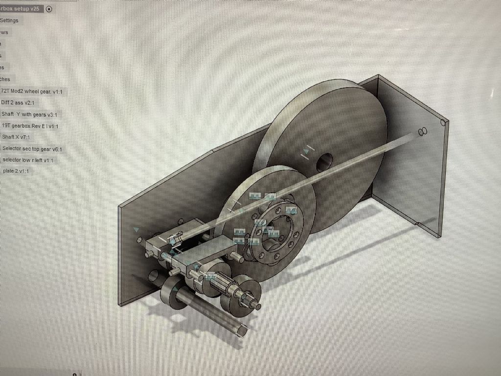
                Thanks for your enquiry in relating to the arrangement of the gears on the Mc Donald. I have tried to follow the original tractor design as far as possible but my selector system is different. The part diagram shows some of the gear ststem. On the right is the large gear wheel (Mod2) that is attached to the rear wheel axle. There are two of these. The central gear is the differential and in the left hand side are the gears for 3 forward and one reverse. The shaft I on the far left carries the reverse idle gear. The gear box is connected to the engine by chain. The diagram to follow.

                #499853
                Four stroke Fred
                Participant
                  @fourstrokefred

                  1ada71f5-d0b3-41ee-81bd-b947d0f9b4f0.jpeg

                  #499868
                  Adrian R2
                  Participant
                    @adrianr2

                    Ah, I see now. I'd assume differential between the axles but clearly not. Coming on well, keep at it.

                    #499993
                    Four stroke Fred
                    Participant
                      @fourstrokefred

                      0a71eb7d-59ab-4076-97e2-cccb76d8088b.jpeg

                      #502625
                      Four stroke Fred
                      Participant
                        @fourstrokefred

                        82aec5bf-6df3-41bc-b4ac-aebe430b02dc.jpegfff5843c-a690-44de-828e-6ba871faacc1.jpeg

                        #502628
                        Four stroke Fred
                        Participant
                          @fourstrokefred

                          The photographs show the process of cutting the gears. The large gears that drive the rear wheels are Mod 2 and the small gears in the differential are Mod 1.5. All gears are in mild steel and the blanks are mounted in a 4 jaw chuck on a square mandrill ( to prevent rotation in the jaws) that has been turned down to suit the centre of the gears. A pin that passes through the blank and into the mandrill is an extra safety factor to prevent any rotation. There are still many gears to cut and then assemble in the gearbox- just hope there are none of the half tooth variety!

                          #507585
                          Four stroke Fred
                          Participant
                            @fourstrokefred

                            Gear cutting continues with now 14 of the 19 gears cut and only 5 more to go. Cutting gears is an interesting operation but requires concentration and no interruptions! At least half of the time is used in setting up but the reward is the finished product. Having cut the gears they then have to set up in the gear case and have the selector mechanism added. More photographs next time.

                            #507601
                            Henry Brown
                            Participant
                              @henrybrown95529

                              Still following with interest Fred and enjoying the great work you are doing! a great idea to put a magnet to catch the swarf but I wondered why you changed the support at the "free" end of the mandrel?

                              #507618
                              colin brannigan
                              Participant
                                @colinbrannigan54160

                                Great work Fred,

                                #507720
                                Four stroke Fred
                                Participant
                                  @fourstrokefred

                                  Good Day Henry,

                                  Thanks for your comments The reason I use I different support in some of the gear cutting is that my four chuck does not allow the Myford end support to be used. If I make the mandrel in the smaller 3 jaw chuck the support arm can then be fitted. The magnet also holds the splash plates in place and keeps the coolant in the work space. More gear cutting today.

                                  Fred

                                  #508844
                                  Four stroke Fred
                                  Participant
                                    @fourstrokefred

                                    059f4fa1-04c5-428e-81d0-aa513e2c6412.jpeg

                                    #508848
                                    Four stroke Fred
                                    Participant
                                      @fourstrokefred

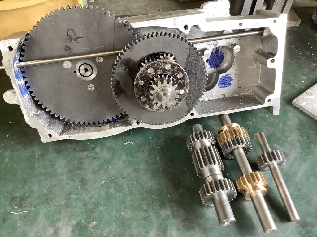
                                      The photograph shows the 18 gears that have been cut for the tractor gear box. They are either Module 1.5 orM 2.0 and are made from steel or bronze. The next task is to cut the key ways in the sliding gears and add the splines to the shaft. I had hoped to use 3 mm key steel for these and then cut 1/8” (3.2 mm) key way slots as this would give sufficient clearance for the gears to slide on the shaft but our local supplier only stock 1/8” so I will have to make some adjustments. The shafts will then be fitted into the gear case and the selector mechanism made.

                                      Fred.

                                      #508877
                                      Dominic Bramley
                                      Participant
                                        @dominicbramley60728

                                        Amazing! Keep it coming!

                                        Dom

                                        #509945
                                        Four stroke Fred
                                        Participant
                                          @fourstrokefred

                                          4cfffb46-6755-41d7-a9d2-298bf9b004d6.jpeg

                                          #509950
                                          Four stroke Fred
                                          Participant
                                            @fourstrokefred

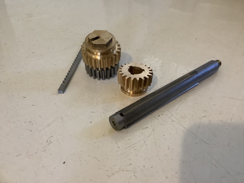
                                            The photograph show today’s effort as I made the splined input shaft for the sliding gears. The splines were made by cutting the grooves with a Woodruff key cutter as this gives clean sides and grooves of the correct width. The splines are made from 1/8”” key steel and are spaced at 120 degrees and are held in place by Loctite. A jig was made for cutting the internal grooves in the bronze gears/ bushes and a broach was pushed through. At present the fit of the gears on the shaft needs to be freed up as they have to slide freely on the shaft but that’s tomorrow’s job. Summer is here and the shed temperature today was 32 C but I can’t wait to get back in there tomorrow and press on with the project.

                                            Fred.

                                            #509952
                                            Adrian R2
                                            Participant
                                              @adrianr2

                                              What make is your mill? You seem to get very good results from it, having that many gears mesh properly must be satisfying.

                                              #509966
                                              Four stroke Fred
                                              Participant
                                                @fourstrokefred

                                                Good Day Adrian,

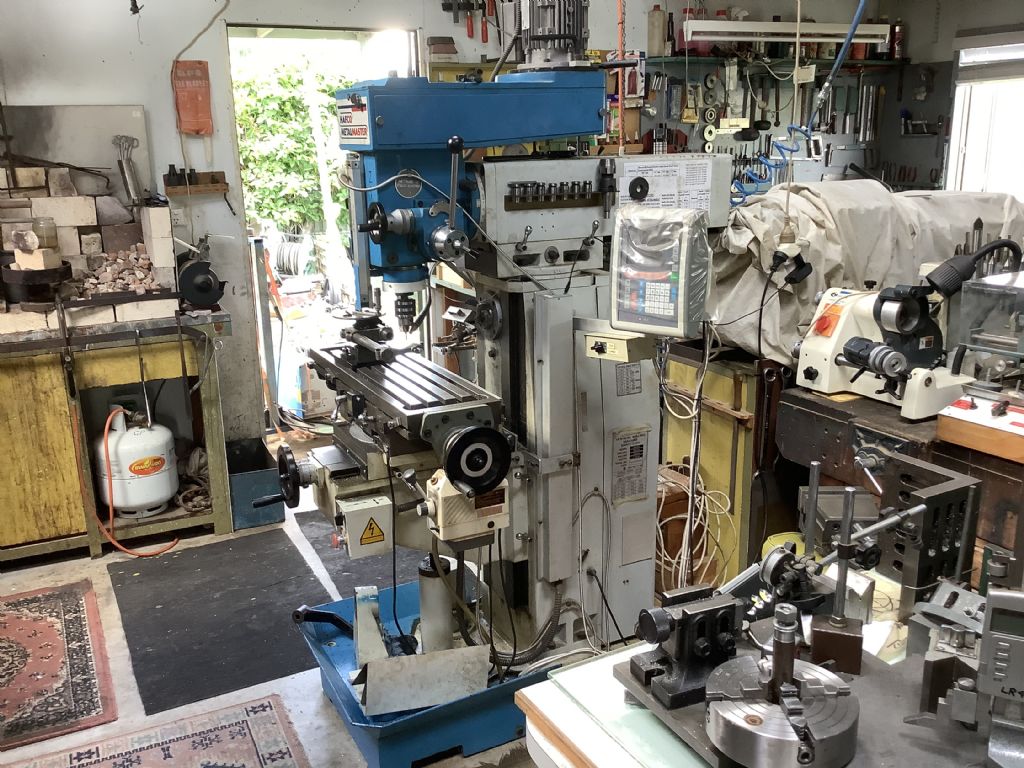
                                                The mill I use was purchased from an Australian company ( Hare and Forbes) a few years ago and is of Asian origin. It is both horizontal and vertical and I have now fitted a good quality DRO and find this a valuable asset. When cutting gears the dividing head needs to be very secure and it take just as much time to set up as to cut the gears.I used “ buttons” and a dial test indicator to set up the gears.

                                                Fred.

                                                #510082
                                                Four stroke Fred
                                                Participant
                                                  @fourstrokefred

                                                  9203f6ef-8e7e-4caa-9896-5de4283f4198.jpeg

                                                  #511169
                                                  Four stroke Fred
                                                  Participant
                                                    @fourstrokefred

                                                    b379815f-a2d6-4917-a6c9-7c0f94aa8256.jpeg

                                                    #511174
                                                    Four stroke Fred
                                                    Participant
                                                      @fourstrokefred

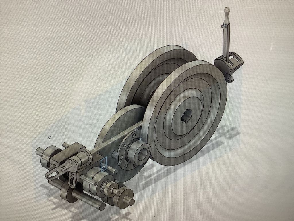
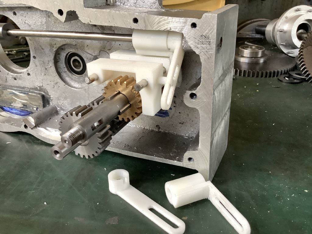
                                                      Having now cut all the gears it is time to work on the selector system. There are two selector forks mounted in a 6 mm shaft with the gear handle at the rear of the tractor. Before making these parts in metal I decided to 3D print them to check there was sufficient room in the gearbox. The photo shows these parts in prototype stage – there will be some minor changes to be made before they are translated into metal.The gear shaft has a pin that locates in side the selector bodies and when the gear lever is moved forwards or back and the side to side to match the “H” gate at the rear of the tractor the appropriate gear should be engaged! An indent will hold the gears in place. The task for the next week is to have all of this system working

                                                      Fred.

                                                      p.s. Is there any one else out there building model I.C. Powered tractors?

                                                    Viewing 25 posts - 26 through 50 (of 359 total)
                                                    • Please log in to reply to this topic. Registering is free and easy using the links on the menu at the top of this page.

                                                    Advert

                                                    Latest Replies

                                                    Viewing 25 topics - 1 through 25 (of 25 total)
                                                    Viewing 25 topics - 1 through 25 (of 25 total)

                                                    View full reply list.

                                                    Advert

                                                    Newsletter Sign-up