Mc Donald Model tractor

Advert

Mc Donald Model tractor

Home Forums Work In Progress and completed items Mc Donald Model tractor

Viewing 25 posts - 276 through 300 (of 359 total)
  • Author
    Posts
  • #603488
    Four stroke Fred
    Participant
      @fourstrokefred

      Lee that sounds to be very similar to our Liquid Nails. It has a rubbery texture with plenty of body and sticks to your fingers very well! Accept the A 7 engine as a self inflicted challenge! The use of a 3D printer to prototype parts is very useful and tactile as they can high light problems with the design that you may not at first see. I have been working on this casting for about the last ten months and the 3D prints were used as both patterns and core boxes. Having the use of this type of technology (CAD and 3D printing) does make life easier.

      Fred.

      Advert
      #603496
      lee webster
      Participant
        @leewebster72680

        I am surprised that the liquid nails withstands the heat of the pour. Do you use water based or spirit based?

        If I can't make a greensand mould, the pattern has some small details that might not survive the extraction of the pettern from the mould, I have some epoxy resin bought from a local boat chandler.

        A new resin 3D printer is on it's way. I hope to get prints from it that need less preparation than those from my Ender3. A good printer, but it has its limitations.

        Lee

        #603502
        Howard Lewis
        Participant
          @howardlewis46836

          ABSOLUTELY fantastic!

          I stand in awe of your persistence and skill

          Persistence pays off

          Howard

          #603506
          DiogenesII
          Participant
            @diogenesii

            Looking very good indeed, Fred..

            #603537
            Four stroke Fred
            Participant
              @fourstrokefred

              Lee, Liquid Nails must be a spirit based glue as washing the hands in water does not remove it. When using it to glue the blocks together I keep it away from the edges of the joint that are exposed to the molten metal. This leaves a small flashing on the casting but that is easily removed later. I do seal the outside of the joints just in case there is any small leaks. I also use an Ender printer with a working volume of 250x250x250 and work in both PLA and ABS.

              Fred.

              #603538
              lee webster
              Participant
                @leewebster72680

                That is a lot of useful information, Thanks Fred!

                Lee

                #603542
                Hopper
                Participant
                  @hopper

                  If you Google "Liquid Nails MSDS" you can download the list of ingredients. For some reason it wont let me cut and past the list onto this site.

                  Basically a solvent-based high-strength construction adhesive.

                  #603572
                  lee webster
                  Participant
                    @leewebster72680

                    Fred, I am looking forward to trying this process.

                    Lee

                    #603578
                    PatJ
                    Participant
                      @patj87806

                      Great work Fred !!!

                      .

                      #605337
                      Four stroke Fred
                      Participant
                        @fourstrokefred

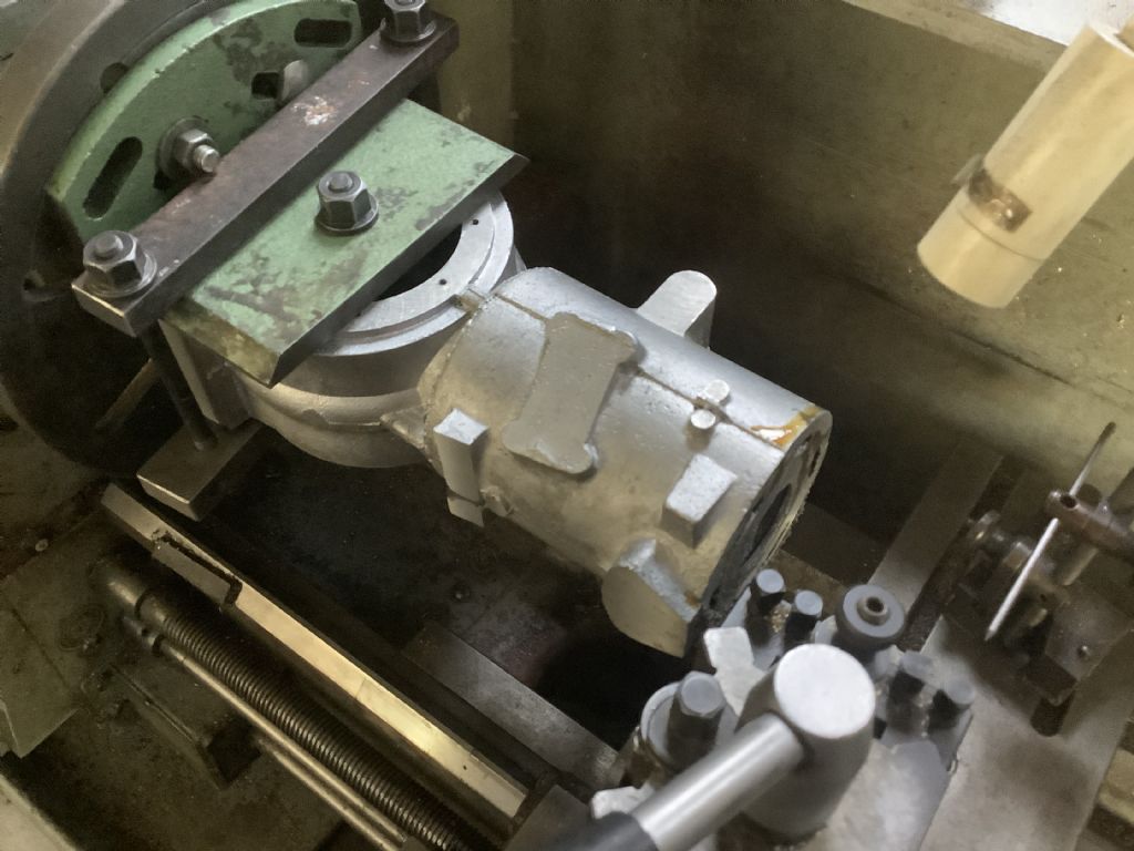
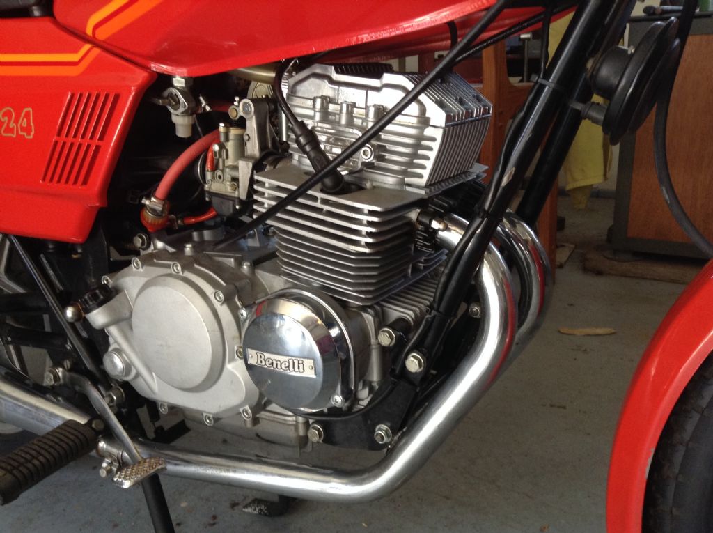
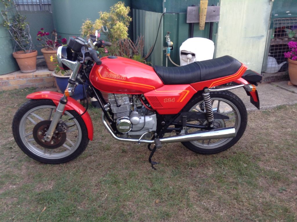
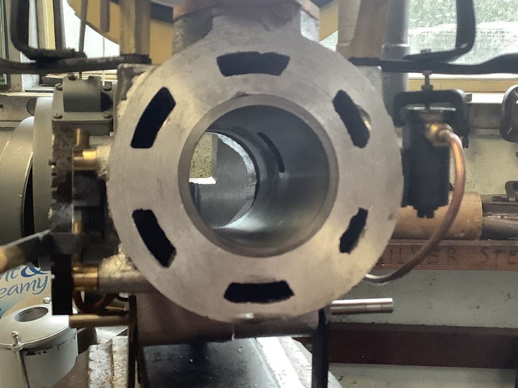
                        1b50a9c6-76d3-46cc-8764-daa92b644958.jpegNo this is not a repeat of a previous photo but the new casting set up and having the end of the bore faced off. The lower part of the crankcase has already been machined and has had the bearing plate and injector fitted (not shown in the photo.)The process is slow due to the fact that setting up an article of this shape and size just takes time. Drilling four holes took half an hour ( 25 minute setting up and 5 minute drilling). Due to the set up in the lathe the process of facing the end of the cylinder is slow and it takes 10 minutes for every pass, any faster and centrifugal forces come in to play with disastrous consequences! I hope by the end of the week to have the bore machined to the 50mm diameter ready for the cast iron liner. I will probably make a dummy aluminium liner that is a sliding fit so the I can mark out the ports before making the working liner in cast iron.The photographs that I have taken with the previous two efforts have been very useful for reference when setting up this casting for machining. Last weekend I went to the local car, truck and motorcycle show and took my 125cc OHC twin Benelli (1982) – a great day out.

                        Fred.

                        #605339
                        Four stroke Fred
                        Participant
                          @fourstrokefred

                          d2086397-a6e7-4e0b-bb0b-3e83bde96bf1.jpeg1368084b-7e6e-41b5-8446-135a2b22be8f.jpegA “ model” motorcycle – makes a change from tractors!

                          Fred

                          #606378
                          Four stroke Fred
                          Participant
                            @fourstrokefred

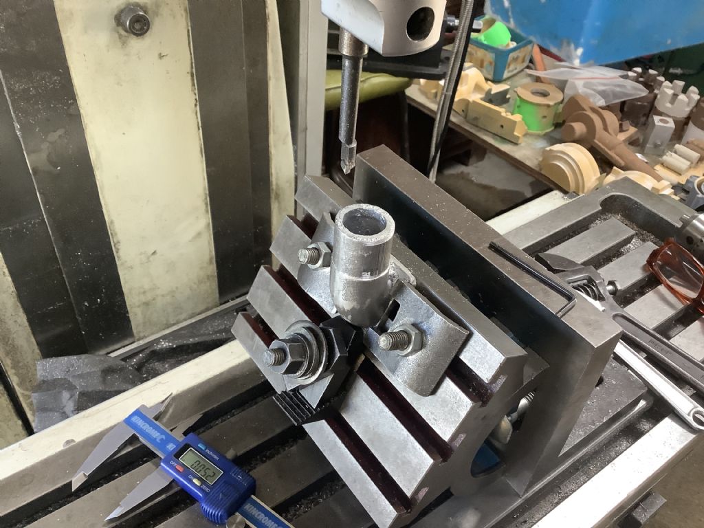
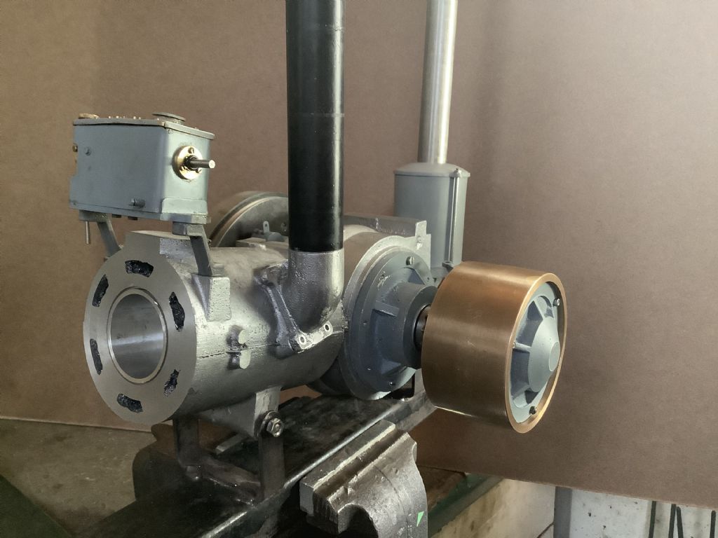
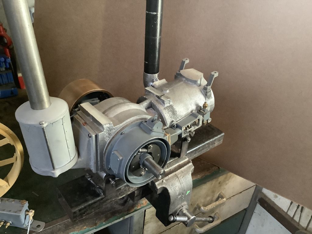
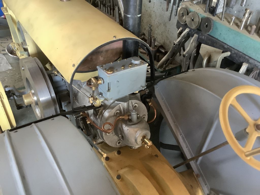
                            d0a7d505-140e-4e09-981f-f0b499932266.jpeg64d5cbe7-ccd7-4d90-8bdb-19329083ba71.jpeg80eba4d3-f323-4f5d-bad8-4925a246a1d2.jpegThe casting proved to be satisfactory and has been machined as can be seen in the photographs. This week I started the process of assembling some of the parts of the engine to make sure they all line up with where they are supposed to go and made a stand to hold the unit making life a little easier.The assembly includes the crankshaft /piston as I have now made a temporary liner which will later be used to check the port positions before making the real one from cast iron. The top photo shows the method used to machine the exhaust manifold – tricky but satisfying when finished. I have made the exhaust pipe a sliding fit and it will be held in place by a small grub screw as this will enable the pipe to be removed for ease of transportation and a reduction of volume should I every go the UK (MEX). I now have to make the fuel tank supports, fit the lubrication system ( the arms shown are 3D prints but will later be cast in aluminium) and add the water inlet and outlet holes. This tractor has a chain drive from engine to gearbox and is tensioned ( on the full size machine) by raising the front engine mount but as this is carried out the air and exhaust pipes are no longer vertical! I may tension the chain on the model by using a slipper tensioner but have to wait until the chain is fitted before I come to a decision. There are still problems to solve but life in the workshop is never dull.
                            Fred.

                            #607264
                            Four stroke Fred
                            Participant
                              @fourstrokefred

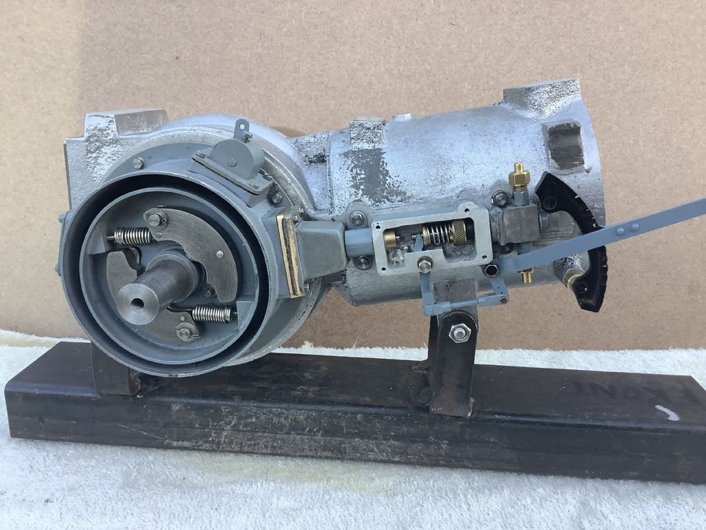
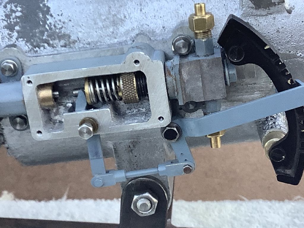
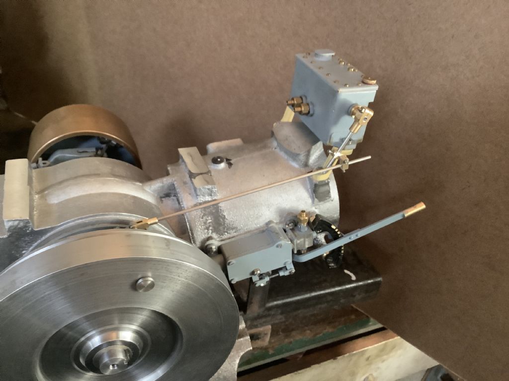
                              This weekends workshop time was spent on the injector set up ( but not the timing). These small parts take longer than expected to both make and then set up and there seems very little to show for the hours it has taken, but it’s all to do with the vision of the end product. Each division on the throttle “gate” is 5 degrees and equates to half a mm of movement on the injector plunger via all the levers. If this amount of movement is excessive there is provision for the leverage to be changed but experimenting will determine if that is required.The crankshaft has yet to have the flywheel keyway cut but as this keyway may also drive the eccentric for the injector I have held off the process.

                              Fred.

                              85a72acd-c254-4404-9a9f-e8c819bc6cd4.jpeg

                              #607265
                              Four stroke Fred
                              Participant
                                @fourstrokefred

                                18283a51-7671-4ebb-a917-b3f46975deb1.jpeg

                                #607270
                                Roger B
                                Participant
                                  @rogerb61624

                                  Still following with interest having spent several years playing with small fuel injection systems smiley

                                  #607731
                                  Four stroke Fred
                                  Participant
                                    @fourstrokefred

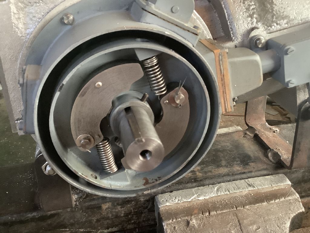
                                    2890d5e0-5deb-49e9-a5af-3eba074d6cbd.jpegLast night I watched a video of a slow running model hot bulb engine made in Holland (I think).It was beautifully made and ran like a Swiss watch. The builder had aimed for a slow running engine and certainty achieved that.The compression ratio was 8:1, a heavy flywheel was used and the injection was fairly early on in the compression stroke, all points that I am hoping to transfer to the Mc Donald. The photographs shows the advance/ retard mechanism with the two grub screws that are use to set the position of the eccentric that works the injector pump. When the final position has been made a keyway will be cut in the eccentric to give it a permanent position – the keyway has already been cut in the shaft. The oil tank has been set up and appears to work OK and the right hand side of crankshaft has been pressed together and scotch keyed in place.

                                    Fred.

                                    3dd755bf-216b-41ee-8813-fa199fabd60c.jpeg

                                    #607799
                                    Howard Lewis
                                    Participant
                                      @howardlewis46836

                                      Your excellent work continues!

                                      It won't be too long before you hear it running!

                                      Howard

                                      #607953
                                      Four stroke Fred
                                      Participant
                                        @fourstrokefred

                                        Today more 3D printing and casting. These are the saddle’s for the fuel tank and when cleaned up will be bolted to the top of the engine.

                                        Fredd393f4ab-1d41-4180-987c-f4670c82885a.jpeg

                                        #609133
                                        Four stroke Fred
                                        Participant
                                          @fourstrokefred

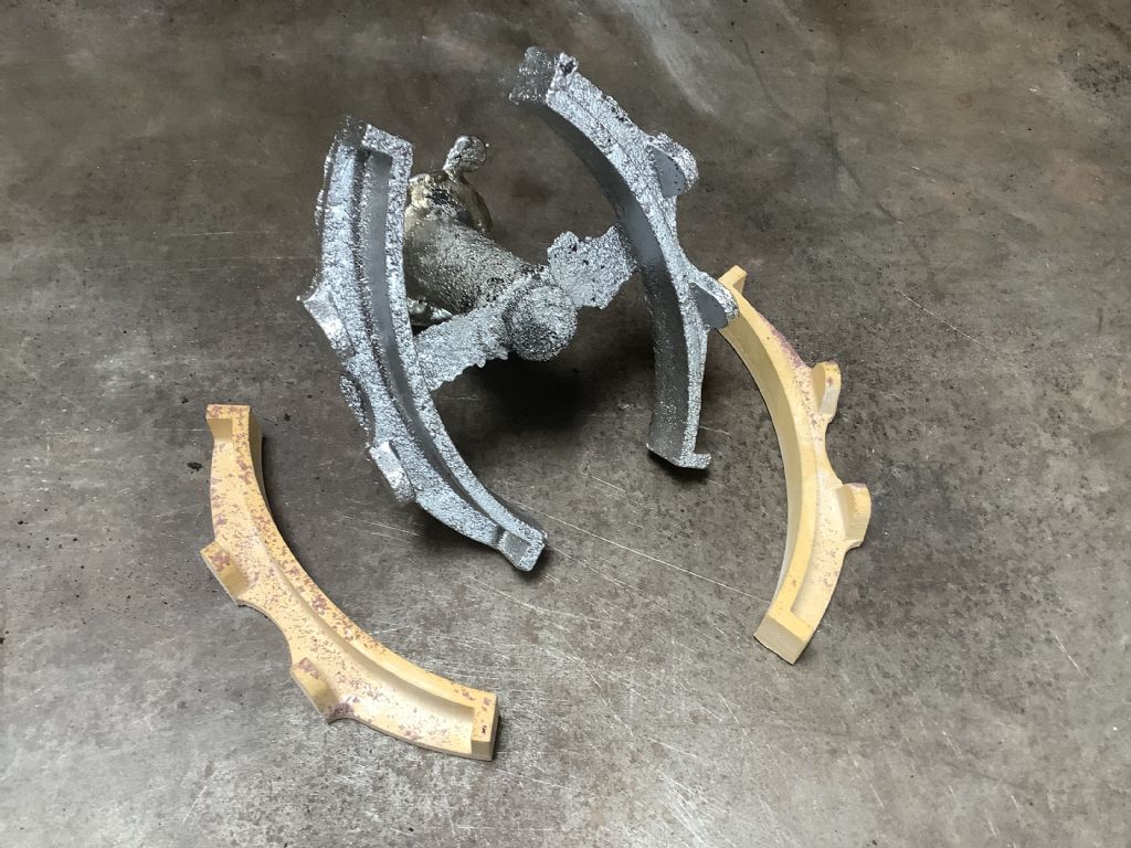
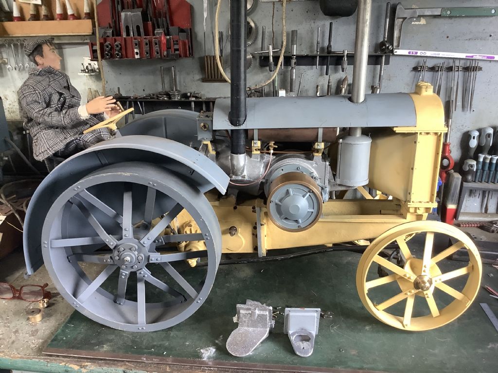
                                          b29d5fd8-d92b-43ca-ba18-cc02077eddff.jpegThis week it was a case of one step back and two steps forward. On assembling the air intake I discovered that the air pipe was obstructing the water pipe on the header tank of the radiator. The cause of the problem was the casting that joins the air box to the back of the engine. I had made the casting on the centre line when actually a part of it was offset from the centre line – this can be seen with the two castings in front of the tractor. The one on the right was the first attempt and the one on the left shows the amount of offset require. This was not easily seen on the full size tractor and only another visit and more photographs resolved the problem. After making a new pattern and core box it took me 4 attempts to make the new casting with the cause of the problem being the placement of the in gate. As they say if at first you don’t succeed try ,try and try again! The fuel line and filter have been fitted and the holes in the bonnet cut. There are still plenty of small jobs to do and that includes machining the cast iron liner from a 60mm diameter bar – boring.

                                          Fred.

                                          #609143
                                          Howard Lewis
                                          Participant
                                            @howardlewis46836

                                            You are making good progress!

                                            Looks really good!

                                            Howard

                                            #609511
                                            Four stroke Fred
                                            Participant
                                              @fourstrokefred

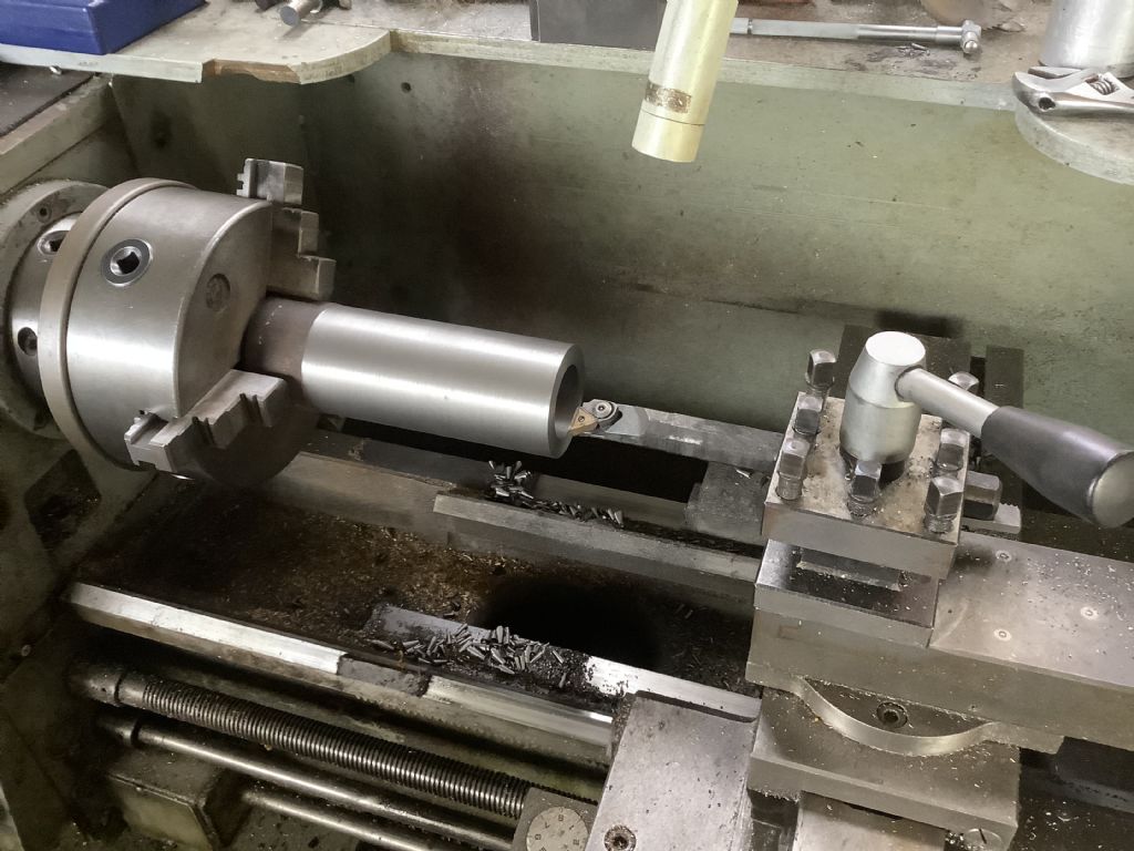
                                              67889d81-a9b4-4743-aea4-8c38e6ef18cd.jpeg541b9fe9-ccee-4411-bb00-fef901766cee.jpegBoring, that was the order of the day – boring the cylinder liner that is. The bar of iron was 60mm diameter and had to reduced to 55 mm and bored out to 45mm diameter. Waste was high but that was the only material I had in stock. I still have to finish the bore, outside diameter and then machine the ports.The fuel tank is now in its final position and has now been fitted with a filler and cap. The bonnet has had the holes cut for the exhaust ,inlet and fuel filler and the support stays added. The fuel lines and lubrication pipes have also been added. The list of jobs that still require attention is now shorter but it’s all the small jobs that seem to consume vast quantities of time. Beware this hobby of model engineering is addictive!

                                              Fred.

                                              #611730
                                              Four stroke Fred
                                              Participant
                                                @fourstrokefred

                                                The list of jobs continues to reduce. This weeks work included the connecting up of all the water inlets and outlet pipes but the main effort went into machining and fitting the cast iron liner. Machining the bore was a long task as the final cuts were very small and lathe speed very slow ( about 20 minutes per pass )Having machined it to the required size both inside and out I was ready to press the liner into the cylinder. Guide lines were marked to line up the ports with the port holes in the liner. All went well with the fit being just right and in line with the top of the cylinder but a check revealed that the liner had rotated slightly as it went down the bore – oh bother! Next job was to make an extractor jig to remove the said liner. Double checks we’re made and this time all was well with all ports in the liner matching up with the ports in the casting. The piston complete with rings can now move up and down the cylinder. The next major job is working on the cylinder head. I also have to make and fit the rod that connects the clutch lever to the clutch and make and fit the chain drive to the gearbox. Photo to follow.

                                                Fred.

                                                #611731
                                                Four stroke Fred
                                                Participant
                                                  @fourstrokefred

                                                  c4bf52cc-60ae-4320-8c3e-1c7383fc9270.jpeg

                                                  #611805
                                                  DiogenesII
                                                  Participant
                                                    @diogenesii

                                                    ..still following with interest and looking forward to the next instalment..

                                                    ..that must be most of the main assemblies for the motor 'done' now?

                                                    ..good stuff!

                                                    #611877
                                                    Martin W
                                                    Participant
                                                      @martinw

                                                      Absolutely brilliant and like DiogenesII I look forward to your postings on this EPIC project. It will be great to see the final build and the engine running, hopefully, at a slow tick over. What are you going to do after this build is finished? Another similar build or take a well earned break and reflect on this project's highs and lows and how problems were solved. I wish I had the skills and dedication to even contemplate undertaking something much less demanding.

                                                      Martin

                                                    Viewing 25 posts - 276 through 300 (of 359 total)
                                                    • Please log in to reply to this topic. Registering is free and easy using the links on the menu at the top of this page.

                                                    Advert

                                                    Latest Replies

                                                    Viewing 25 topics - 1 through 25 (of 25 total)
                                                    Viewing 25 topics - 1 through 25 (of 25 total)

                                                    View full reply list.

                                                    Advert

                                                    Newsletter Sign-up