Mc Donald Model tractor

Advert

Mc Donald Model tractor

Home Forums Work In Progress and completed items Mc Donald Model tractor

Viewing 25 posts - 226 through 250 (of 359 total)
  • Author
    Posts
  • #586010
    Four stroke Fred
    Participant
      @fourstrokefred

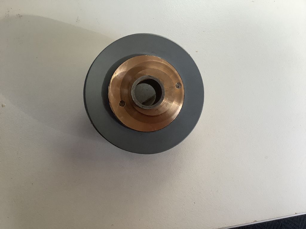
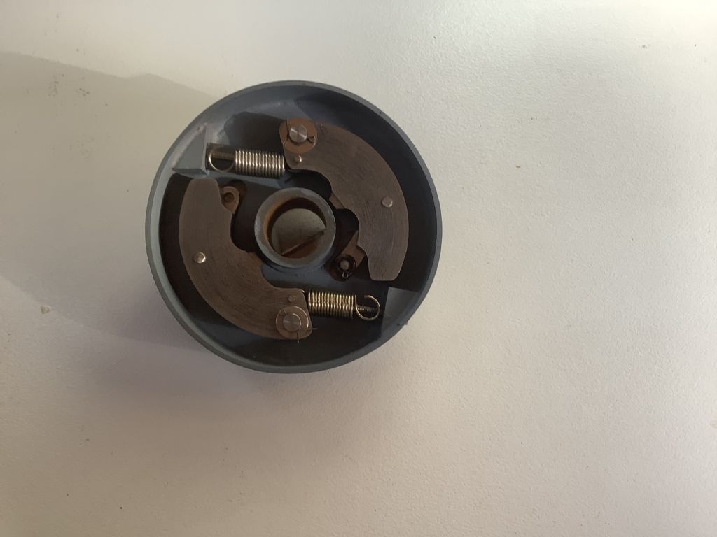
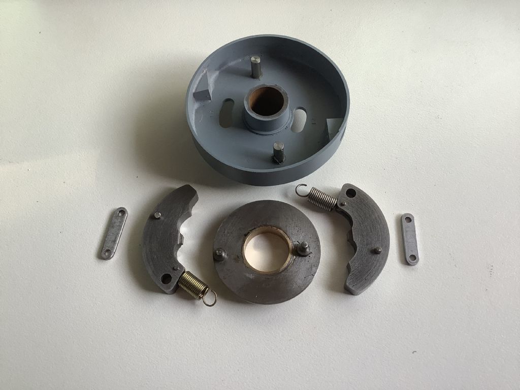
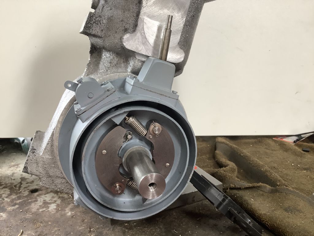
      The photographs show progress on the governor. I still have to add the spring adjusters and test to see what speed the cast iron weights throw out to the outer limits. The eccentric is made from bronze and will have a steel eccentric sleeve/ rod when it is made. Having studied the injector pump arrangements on the Lanz I now understand how it works – the outer eccentric gives the pump stroke and the inner concentric one gives the advance/ retard but I have made mine as shown on one of the sets of drawings for the Mc Donald. If I find after test this does not work I will have to change the design. The reason for choosing this is because there is very little room for two eccentrics and there are less parts to make! The next part to make is the injector pump.

      Fred.

      a69031bf-5cfa-46e4-a8ff-3acd0bd118e7.jpeg96fed6e6-9a1b-42e5-bae9-4af412029155.jpeg3135c61d-3b26-4a36-aa65-743449a0413a.jpeg

      Advert
      #588526
      Four stroke Fred
      Participant
        @fourstrokefred

        f8aaead6-71ad-4761-9568-c45f606bf8da.jpegThe photo shows progress this week and it doesn’t look like very much! It’s what you can’t see that has taken the time as it all happens behind the bob weights. I have made and fitted the cover and added various parts.The injector plunger that activates the pump can be seen protruding from the the top and on the left is the arm that operates the oil pump. Further to the left is the inspection hatch that enables the governor springs can be adjusted. Having drawn all these parts they were then 3D printed to give an idea of the full size model parts. The drawing of the parts on the screen gives a false impression of size but having them in your hand is reality. The injector pump and valves will be the next part to be made as weather condition have halted any attempt to make castings ( we work in the open air).
        Just a few facts on our weather that may interest you – parts of the east coast of Australia has been hit by a band of very heavy rain but fortunately most of it has missed our area. One Queensland river rose 25 metres, another place had 700 mm in one day and we had hot steamy nights with 27C being recorded at 3.0am! We are looking forward to cooler and drier times.

        Fred.

        #589435
        Four stroke Fred
        Participant
          @fourstrokefred

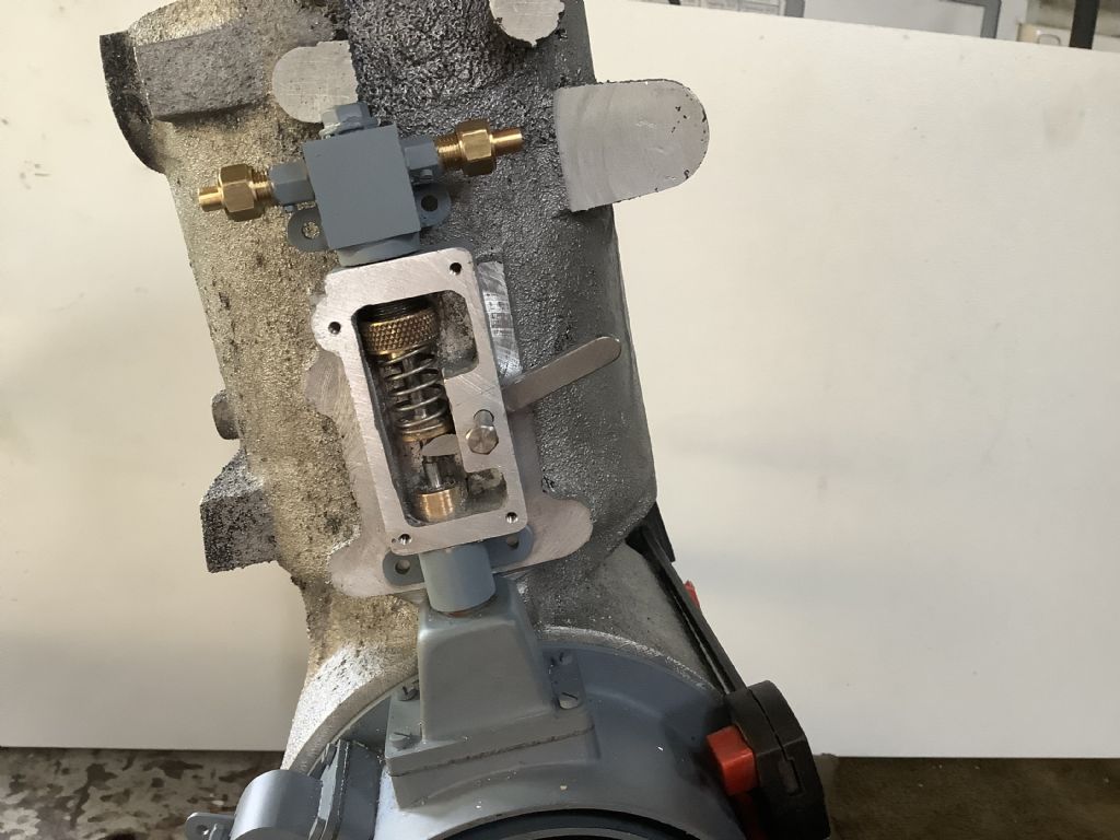
          This is the injector pump with the cover removed to show what is happening inside. The brass fittings are one way valves that allow fuel in from the tank and then pumped out to the injector nozzle. As the cylinder is almost horizontal gravity is used to seat the ball valves with small 12 BA pins used to prevent them from “ jumping” to far off the seat similar to the check valves used on model steam locomotives.The handle on the right controls the amount of fuel being pumped to the injector and is connected by levers to the drivers end of the tractor. The knurled part holds an “O” ring in place to help form a seal between the 1/8” piston and cast iron cylinder. I now have to start to think about the cylinder head and that will be a really interesting part to design and make but that for next week!

          Fred.

          ​​​​. The e0464c59-5fe3-4187-b066-959f878d397a.jpeg

          #589436
          Michael Gilligan
          Participant
            @michaelgilligan61133

            I continue to be amazed

            MichaelG.

            #589439
            DiogenesII
            Participant
              @diogenesii

              That's a neat metering solution.. ..still watching with interest, thanks for posting so much of the detail..

              #589446
              Four stroke Fred
              Participant
                @fourstrokefred

                Thanks for your comments. After all this time and effort there is no guarantee that it’s going to work but it’s good fun trying and a great learning process.

                Fred.

                #589915
                Four stroke Fred
                Participant
                  @fourstrokefred

                  1f3b27d0-07a6-451a-8800-0fc6a4a73f6f.jpegabfc1e24-f604-4e5c-b9ee-d43797c9d261.jpeg8bcc97fd-3f9e-4b5d-b67b-5a5cb31eba7a.jpeg

                  #589916
                  Four stroke Fred
                  Participant
                    @fourstrokefred

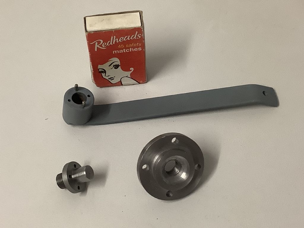
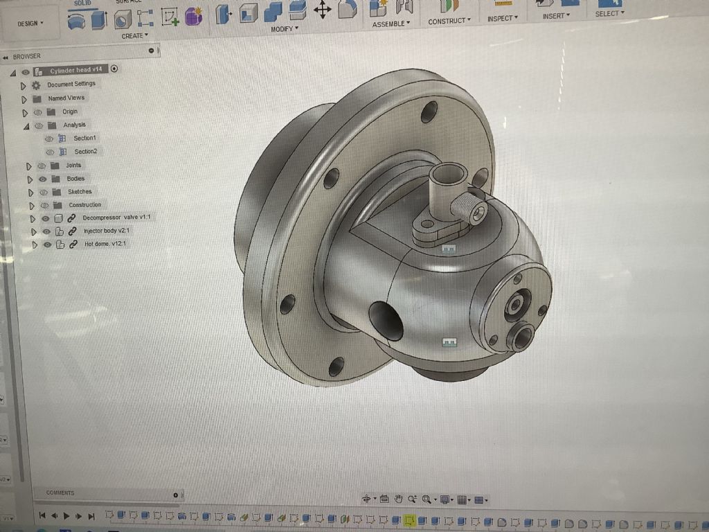
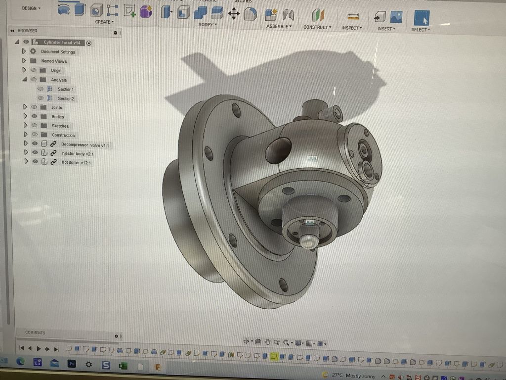
                    These are the 3D drawings of the cylinder head with the injector on the top and the hot bulb on the under side. The top photo shows the hot bulb and special peg spanned and the lower part of the combustion chamber all made from steel.I may need to experiment with more hot tubes of various thicknesses and lengths but will have to wait until the rest of the engine is made to test what will actually work. The match box gives some idea of scale. The next stage is to make 3D patterns for the main part of the head and then cast them in aluminium.

                    Fred

                    #589973
                    Roger B
                    Participant
                      @rogerb61624

                      Still following along and enjoying smiley

                      Is there room to fit an automotive diesel glowplug in the combustion chamber for the first trials? It could remove some of the uncertainty as you know it will be hot enough to ignite so you can concentrate on the fuel injection.

                      #590031
                      Four stroke Fred
                      Participant
                        @fourstrokefred

                        Good Day Roger
                        Thanks for your comments. On the full size tractor there is a place for a plug ( glow or spark) and I have incorporated this in my model and is the hole on the left hand side of the cylinder head. I was told these were used for the starting process in places where the climate is cooler and it is harder to keep the bulb hot. I can fit a 1/4 x 32 commercial glow plug and may use that for initial testing.

                        Fred

                        #591332
                        Four stroke Fred
                        Participant
                          @fourstrokefred

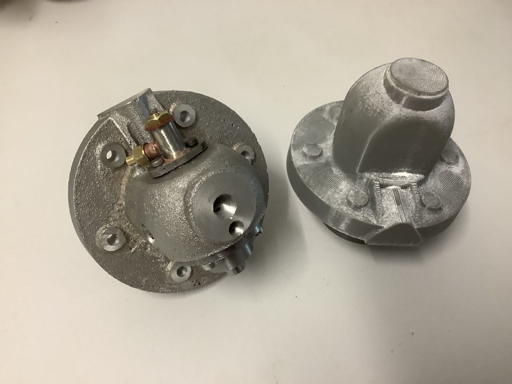
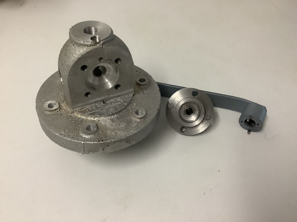
                          860488fd-900c-482d-8ec5-089238b94beb.jpegThis photograph shows progress so far on the cylinder head with the 3D printer pattern on the right and the real part on the left. The larger of the two holes on the front is for the decompressor valve and the hole below is for the escaping gas. The recess on the left is for a glow plug and yes this was fitted to the full-size tractor and used in cooler climates to help with the starting. In some cases they may have used a spark plug and a trembler coil to provide a cascade of sparks. I will also post a photo of the combustion chamber and the underside of the head/ hot bulb. The bulb is detachable and I may have to experiment with lengths and thicknesses but that’s for later.

                          Fred.

                          #591333
                          Four stroke Fred
                          Participant
                            @fourstrokefred

                            fd952fec-6647-4832-a46f-eed869e78296.jpegThis shows the pre combustion chamber and the hot bulb with its special peg spanner. The castings still have to be cleaned up and made presentable.

                            Fred.

                            #591397
                            Adrian R2
                            Participant
                              @adrianr2

                              Was cartridge start an option for these beasts? That would be an interesting thing to reproduce at model scale.

                              #591403
                              A Smith
                              Participant
                                @asmith78105

                                Really interesting work Fred, please keep posting.

                                Andy

                                #591439
                                Roger B
                                Participant
                                  @rogerb61624

                                  I don't think that hot bulb engines used cartridge start as you didn't have to get them over compression. They were typically bounced off compression in the wrong direction and hopefully started running in the correct direction of rotation.

                                  Cartridges as far as I know were used for starting full diesels where they had to be got rapidly over compression.

                                  If I get my diesel running well I suppose a blank .22 cartridge could be an option wink

                                  #591488
                                  Four stroke Fred
                                  Participant
                                    @fourstrokefred

                                    Thanks for the comments from those who are following the progress on this model and good to hear that you are making a Diesel engine Roger ( what is it?) They do present a real challenge but that’s what makes life interesting. The Mc Donald did not use a cartridge type start. The flywheel has a retractable sprung loaded handle and the engine is “ rocked” until it bounces of compression and fires up. I hope the model will do the same but I expect there will be teething problems and I will just have to try to solve them one at a time.

                                    Fred

                                    #591570
                                    Roger B
                                    Participant
                                      @rogerb61624

                                      I mentioned a little bit about my diesel at the start of this thread however things have moved on. I have been experimenting with fuel injection for some time and have successful manifold injection systems for Petrol/Gas/Benzin. The diesel injection system appears to reach around 100 Bar but good atomisation is proving difficult. The initial engine was a horizontal two stroke based on the Field Marshall design.

                                      The two stroke diesel would start and run on standard automotive diesel fuel. I believe that an amount of the running was on fuel that had passed by the piston and was vapourised in the crankcase. This was backed up by the amount of oily black clag that comes out of the exhaust and the lack of response to the fuel rack position once it starts.

                                      I am now rebuilding it as a four stroke to allow me to better separate the different parts of the operation cycle. The bottom end and conrod will be retained along with the lubrication system. It will need a new cylinder block piston and cylinder head. This is being documented on Model Engine Maker:

                                      https://www.modelenginemaker.com/index.php/topic,10605.0.html

                                      Here is a video clip of the two stroke nearly running and the initial layout of the four stroke. The stops were due to me reducing the fuel injection quantity. It has a tendency to run away but the air intake is easily blocked with a finger.

                                      https://youtu.be/1OP6LxPb2uU

                                      four stroke diesel.jpg

                                      #593643
                                      Four stroke Fred
                                      Participant
                                        @fourstrokefred

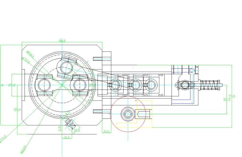
                                        Over the last week I have spent time on redesigning the crankcase patterns and core boxes. One the the unforeseen problems is the alignment of various parts of the model when the dummy engine was placed in position. For example on the full size tractor it is very difficult to measure parts like the engine length and the front mountings as there is no straight line due other bits being in the way! It isn’t until a “ dummy engine” has been made that these discrepancies manifest themselves and have to be corrected. It’s all about that never ending learning curve! I have decided to make the second crankcase pattern in 8 parts and use a chemically bound sand for each part. The 3D printer will be working overtime as all 8 pattern parts will take in excess of 67 hours to produce but that does leave me time to design and make the special casting boxes and to sort out that part of the process. With the last tractor ( Saunderson &Mills) I made it took 8 weeks to perfect the casting of the cylinders and that did not include pattern and core box making. This tractor seems to be following the same path but the end is just around a very long corner. It’s a case of you made the problem you solve it!

                                        Fred.

                                        #593645
                                        Four stroke Fred
                                        Participant
                                          @fourstrokefred

                                          Over the last week I have spent time on redesigning the crankcase patterns and core boxes. One the the unforeseen problems is the alignment of various parts of the model when the dummy engine was placed in position. For example on the full size tractor it is very difficult to measure parts like the engine length and the front mountings as there is no straight line due other bits being in the way! It isn’t until a “ dummy engine” has been made that these discrepancies manifest themselves and have to be corrected. It’s all about that never ending learning curve! I have decided to make the second crankcase pattern in 8 parts and use a chemically bound sand for each part. The 3D printer will be working overtime as all 8 pattern parts will take in excess of 67 hours to produce but that does leave me time to design and make the special casting boxes and to sort out that part of the process. With the last tractor ( Saunderson &Mills) I made it took 8 weeks to perfect the casting of the cylinders and that did not include pattern and core box making. This tractor seems to be following the same path but the end is just around a very long corner. It’s a case of you made the problem you solve it!

                                          Fred.

                                          #593646
                                          Four stroke Fred
                                          Participant
                                            @fourstrokefred

                                            Sorry about the double up

                                            Fred.

                                            #594654
                                            Four stroke Fred
                                            Participant
                                              @fourstrokefred

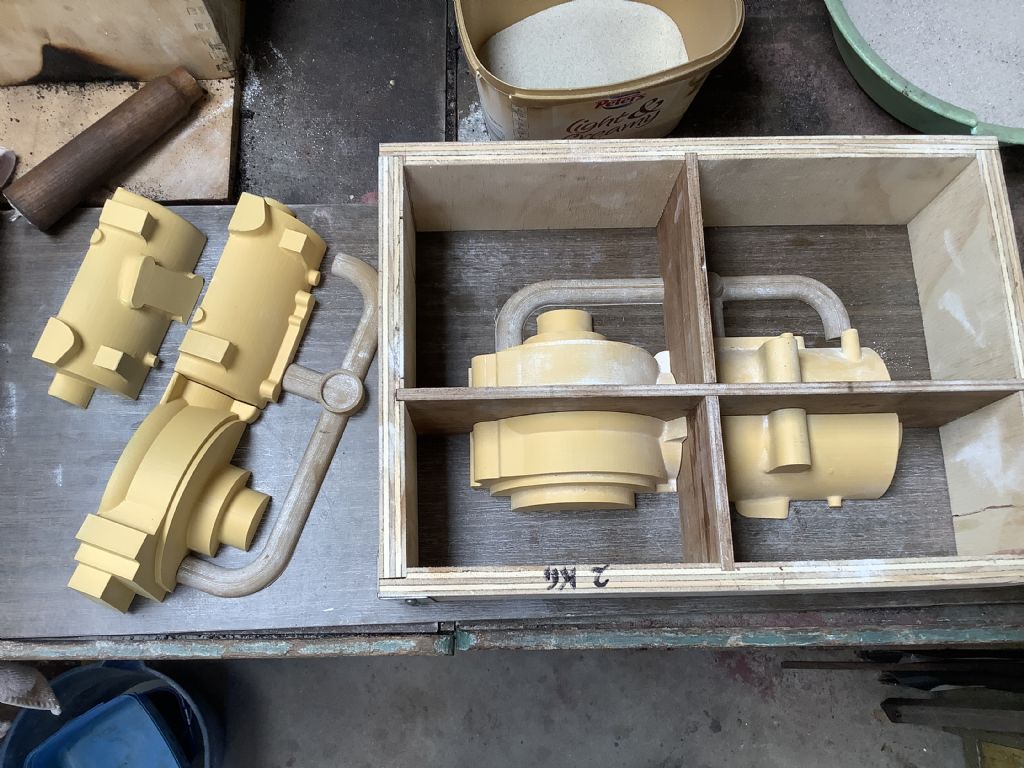
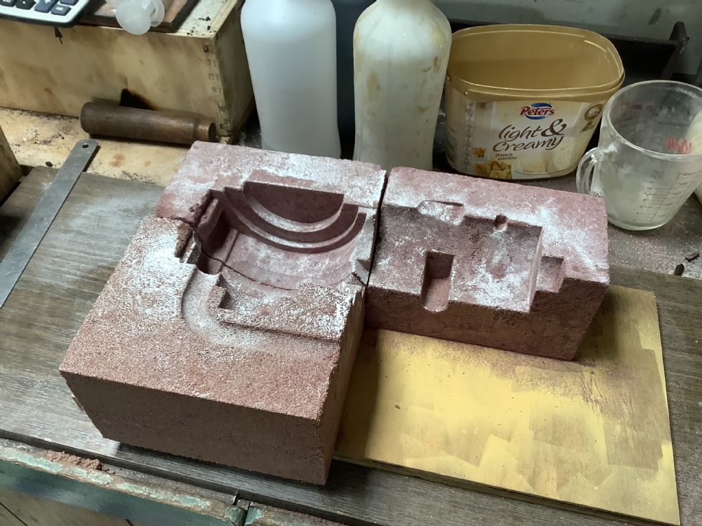
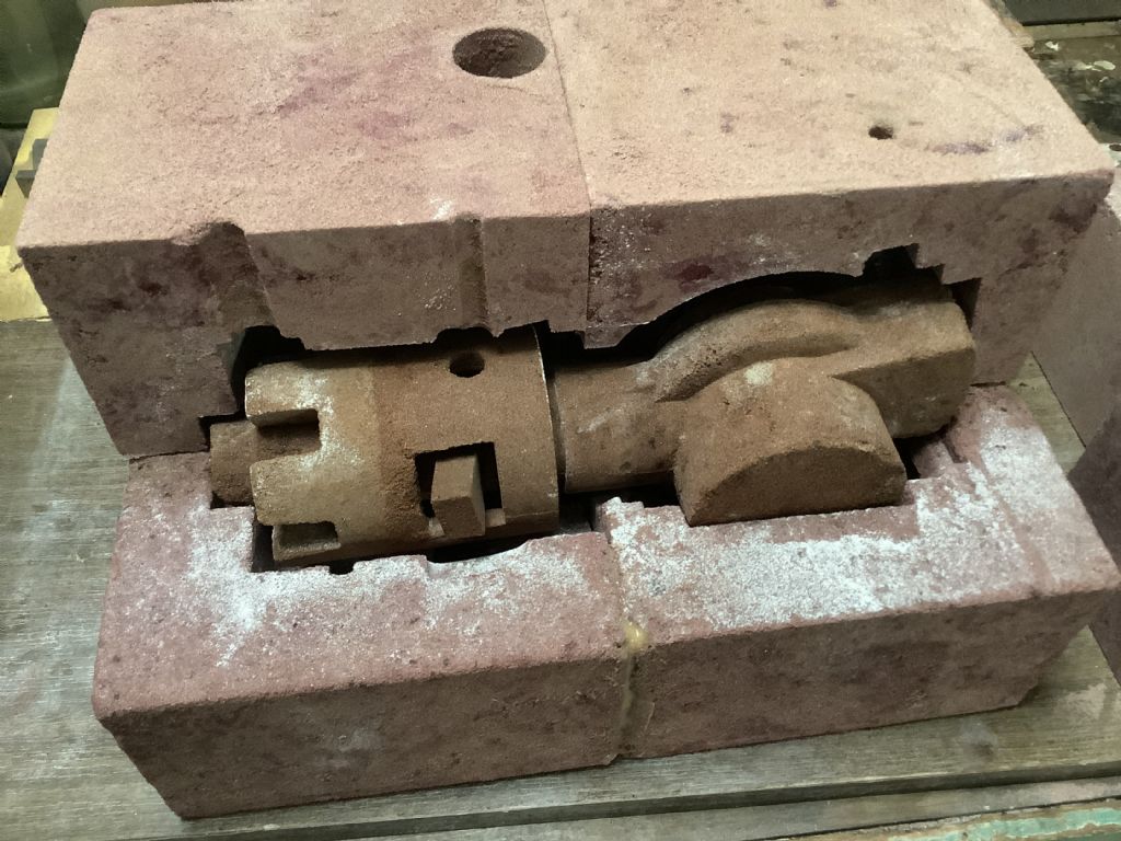
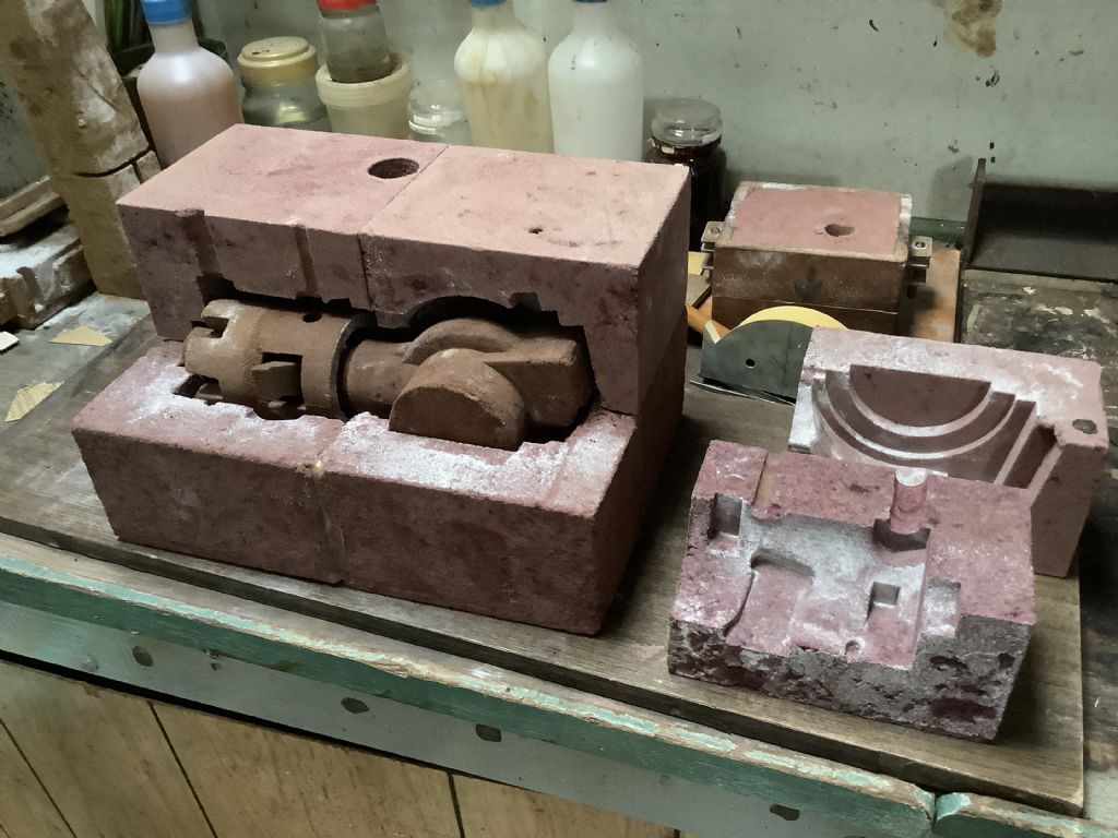
                                              20c1eb5d-a2be-4d0c-bdba-56fcba19e72b.jpeg65 hours of 3D printing resulted in a set of new crankcase patterns.The whole crankcase is divided into 8 parts as this allows the patterns with under cuts to be with drawn easier and gives a better definition and finish than the previous attempt. A special casting box was made in the form of 2 “L” shapes and a divider fits inside to seperate each of the patterns. All the sand blocks will be glued together and a frame added to the outside to keep it all together. Still more sand castles to be made but I have to dry out some more sand before mixing it with the chemical binder. I may have to modify the inner core to fit the new crankcase casting but thats for next week.The photographs show progress so far.

                                              Fred.13207500-7f97-48ca-baae-b47fefb61a27.jpeg

                                              #595039
                                              Four stroke Fred
                                              Participant
                                                @fourstrokefred

                                                3ee77749-00ea-44de-b521-483c10998dd3.jpegf8d38eb6-dbdf-4f73-875f-9fbd41d0b295.jpegSand castles nearly complete I just have to glue on the top half and make sure it is all sealed up ready for the big pour. Hopefully this will be later in the week, weather permitting. The part sticking out from the left side of cylinder is the core for the exhaust port and the small hole in the top is for the oil feed to the cylinder. The weight of the sand blocks and core is about 22kg. I did have to purchase from our local hardware store a couple of bags of fine sand of the type that is normally used in sand pits for young children. This works well and gives a satisfactory finish. Now it’s a case of finger crossed and hope all goes well!

                                                Fred.

                                                #595050
                                                Roger B
                                                Participant
                                                  @rogerb61624

                                                  Good luck for the pour yes That's a complex piece.

                                                  #595375
                                                  Four stroke Fred
                                                  Participant
                                                    @fourstrokefred

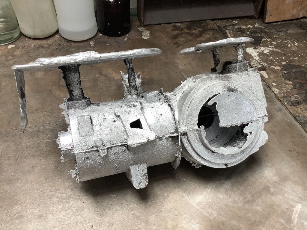
                                                    Today we cast another crankcase- still not perfect but I will have to wait until tomorrow to see if the inside of the water passage is o.k. I have machined datum faces to keep things square but still have to bore out the cylinder and top of the cylinder barrel which will reveal the water passage. Photo shows “ as cast” but the casting has now been cleaned up and partially machined.

                                                    Fred

                                                    f70c903d-2fc6-4443-8253-1ef7ddd0d12b.jpeg

                                                    #595394
                                                    Jon Lawes
                                                    Participant
                                                      @jonlawes51698

                                                      Fantastic work. Thanks for keeping us involved.

                                                    Viewing 25 posts - 226 through 250 (of 359 total)
                                                    • Please log in to reply to this topic. Registering is free and easy using the links on the menu at the top of this page.

                                                    Advert

                                                    Latest Replies

                                                    Viewing 25 topics - 1 through 25 (of 25 total)
                                                    Viewing 25 topics - 1 through 25 (of 25 total)

                                                    View full reply list.

                                                    Advert

                                                    Newsletter Sign-up