Mashstroy C210T / Warco 220 help please

Advert

Mashstroy C210T / Warco 220 help please

Home Forums Hints And Tips for model engineers Mashstroy C210T / Warco 220 help please

Viewing 25 posts - 26 through 50 (of 74 total)
  • Author
    Posts
  • #84326
    Peter G. Shaw
    Participant
      @peterg-shaw75338
      Continued from above.
       
      Last bit – how to get it out in one piece. Obviously this only applies to my style of lathe. If yours is different, then this may not work. Ok, here goes.
       
      First stick your fingers onto the leadscrew, ie under the leadscrew guard. Rotate the leadscrew using the handwheel until you can feel the longitudinal slot in the leadscrew. Now turn the leadscrew using the handwheel until the slot is at the top. (If you do not, then there is a chance you will drop the key out, but do not worry, there is an easy work around that one. How do I know? Don’t ask !!!) Now remove the handle – it is just a normal right hand thread – having made sure that it is in its uppermost position. Once it is removed, open the gearbox cover and pull out whatever is there, (gears if screwcutting, or turning wheels) along with the mechanism. Having got it out, look down the righthand end and you should see the sliding keyway I mentioned above. Look through the big hole on the headstock casting, and with luck you should see the end of the leadscrew with the key still located and uppermost. To reassemble, insert the mechanism ensuring that the sliding keyway is at the top and simply feel it into engagement with the leadscrew. Easy-peasy.
       
      Well, I think it is easy, but then I have had it out a number of times.
      It might be difficult if anything such as the large disk starts catching on say the pulleys, or the spring loaded thingy middle front decides to be awkward. Or even if the expandable spring rings are expanded too much. But I did not have any trouble at all.
       
      Ok, you’ve rotated the leadscrew down and the key has dropped out. Now I have small short fingers and although I can get them in, they are not long enough or thin enough to replace the key. So, here is what to do. At the other end of the leadscrew, undo and remove the adjuster, two screws to slacken, then screw it off. Remove, leave in place, whatever, the thrust bearing – it will most probably drop off whatever you do. Now slide the leadscrew, saddle and everything else towards the left until the end of the leadscrew becomes visible. Now you can replace the key. I actually found that I could replace the key through the gap where the handle fits. Carefully rotate the leadscrew so that the keyway plus key are at the top, slide the whole job lot back to the right, replace the thrust bearing (you did take note of the order of the parts didn’t you), replace the adjuster, adjust as necessary, lock up and Bob’s your Uncle. It might actually be a good idea to replace the mechanism before adjusting, not because it will have any effect on the adjustment, but more to prevent the key dropping ut if you accidently rotate the leadscrew again.
       
      Ok folks, that’s all! Any problems? No? Good!
       
      Regards,
       
      Peter G. Shaw
       

      Edited By Peter G. Shaw on 10/02/2012 19:35:36

      Edited By Peter G. Shaw on 10/02/2012 20:03:47

      Advert
      #84327
      Peter G. Shaw
      Participant
        @peterg-shaw75338
        Roger,
         
        I ain’t not got your screw.
         
        Just a thought. Maybe my operating procedure is different to yours.
         
        Here is mine.
         
        To engage a fine feed, I select the speed by moving the lever sideways to the appropriate position. I suspect that is the same for you.
        Next, I press down the lever until the wheels engage.
        Now, I have to press even further, and harder. What this does, is that it uses the resistance to further movement generated by the engagement of the wheels to lock the left hand side of the mechanism in place (see posts above). Further movement down of the lever now causes the cones to move together thus forcing the split cones (known as cut rings in the manual) to spring and expand thus gripping the inside of the headstock.
        It seems that when using 0.1mm the pressure generated is not sufficient to force the wheels to grip.
        When screwcutting, all is ok except that when reversing, there is a tendency for the gears to jump out of engagement, presumably because the action of the gears is such as to help the mechanism to move out of engagement. Needless to say, I know hold the lever in gear to make sure.
         
        Also Roger, can you describe the type of gib adjustment you have. Is it normal gib strips, a few mm thick? Or is a ginormous CI block that has to be moved around and then clamped back in position? The reason I ask is that I have this ginormous ci block 
        and it’s not easy to adjust. Effectively I have to slacken the three clamp bolts, adjust two adjusting screws hopefully correctly, and then tighten the three clamp bolts and try it. If it still is not right, repeat the above. Unfortunately, because the cast iron block is so stiff, and there are only two adjusting screws, the two screws do intereact such that tightening one up affects the adjustment of the other. Whereas with normal gib strips one can get it right first time.
         
        Regards,
         
        Peter G. Shaw

        Edited By Peter G. Shaw on 10/02/2012 20:26:43

        #84329
        Ivy
        Participant
          @ivy
          Peter,
           
          I appreciate all of the trouble you went to for that picture essay, it certainly will help me or at make it easier to understand when I get stuck into mine.
           
          Thanks again, Ivy.
          #84335
          Peter G. Shaw
          Participant
            @peterg-shaw75338
            Ivy,
             
            Believe it or not, the biggest problem was the actual write up – and even then it was really quite easy. The photos I have now got off to a fine art – get out the digital camera, run off a few shots, upload to the computer, use PaintShop Pro to reduce the size, upload to site, job done.The dismantling also is dead easy, mainly because I’ve done it all before.
             
            So, as I think the Aussies say, ” no worries mate”.
             
            Anyway, come back if you want more. Use the private messaging system if you want. It really does not take long to take a few photos and write a description.
             
            Regards, and good night – it’s my beddy-bies time now. (Actually it’s prepare for bed, and then start reading!)
             
            Cheers,
             
            Peter G. Shaw
            #84386
            Bazyle
            Participant
              @bazyle
              Thanks for the details and photos. It is interesting to see if such a mechanism has possibilities elsewhere.
              I take it that the friction disc engages with a stepped wheel with 3 different diameters for the feeds and there is some spring to ensure friction, and that is one aspect that needs adjustment from the screw menioned in an early post.
              Then the first part of the locking process is to lock the sideways position and then prevent rotation that would reduce the pressure from the aforementioned spring.
              It looks like a simple sheet metal catch pivoted on a screw in the casing could be arranged to hold down the lever and by having a sloping engagement face it would be able to apply whatever force was needed. I would put it just to the right so it could be pushed over by thumb as the lever is engaged.
              #84404
              Peter G. Shaw
              Participant
                @peterg-shaw75338
                Bazyle,
                 
                Yes, the large friction disc does indeed engage with a stepped wheel with three different diameters, each of which has a flange at each side thus ensuring that the disc engages correctly.
                 
                There is no actual physical spring, other than one used to help locate the mechanism positively sideways. If you look at my second and third photos you will see a thin sliding plate with a bit bent over and a rod sticking out at the front. This rod slides over a triple grooved rod to provide the location information. The plate itself slides back & forth and disengages the friction disc and associated little gear wheel from the large gearwheel in the fully disengaged position.
                 
                From what I can see of the mechanism, all the pressure to ensure drive between the friction wheel and the three stepped wheel comes from the hand lever mechanism. I suspect that the combination of low gearing plus the effort required to shift the carriage is borderline for the drive. Certainly in the two higher speeds, it is nowhere near as bad and let’s face it, the effort required to shift the carriage will be the same.
                 
                As I have written this, I have realised that this does not make sense so I will have to have another look at as theoretically, it should work best at lowest speed: a bit like a car with a slipping clutch which will work ok in 1st or 2nd, but slip in 5th & 4th.
                 
                The idea of a sheet metal catch is something I had idly thought about, but as it wasn’t really a problem I never bothered pursuing. In any event, I have a suspicion that the positioning of the lever varies according to the stepped wheel postioning and gear cutting. More to look at.
                 
                I’ll take another photo to show the external visible mechanism. Watch this space.
                 
                Regards,
                peter G. Shaw
                #84416
                Peter G. Shaw
                Participant
                  @peterg-shaw75338
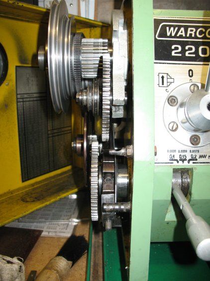
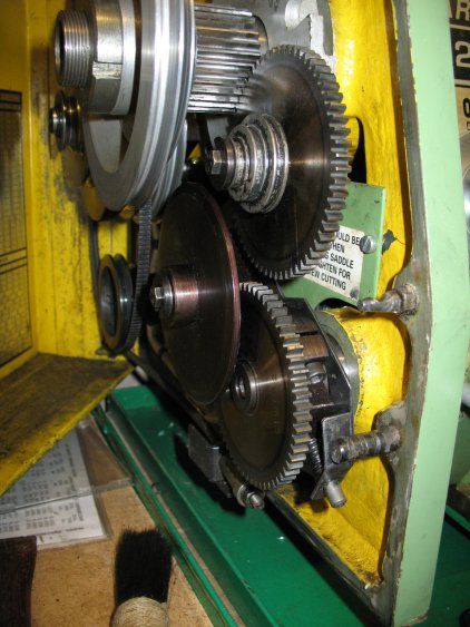
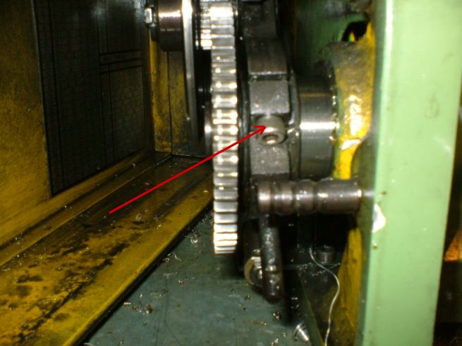
                  As promised two more photos showing the visible mechanism.
                   

                  You will be able to see the disc and the three-step pulley. Also, in the first photo, you can just see the small attached gear wheel which meshes with the large one at the front. Also on both photos can be seen the triple grooved rod which acts to locate the sideways positioning, and the spring loaded mechanism which locks it in place (lower photo).
                   
                  I was right in that the positioning of the operating lever, visible in the top photo, does vary in it’s position when engaged. Which means that any latch to hold it down will have to spring loaded. Indeed, I think it would have to be quite a hefty spring to be of any use.
                   
                  I would still like to know more about Roger’s machine, eg what does the pad bear on to stiffen things up? Does his machine still use the split cones? Presumably the adjustment screw and pad are through the circular part that the handle screws into.
                   
                  Regards,
                   
                  Peter G. Shaw
                   
                  #84448
                  Nicholas Farr
                  Participant
                    @nicholasfarr14254
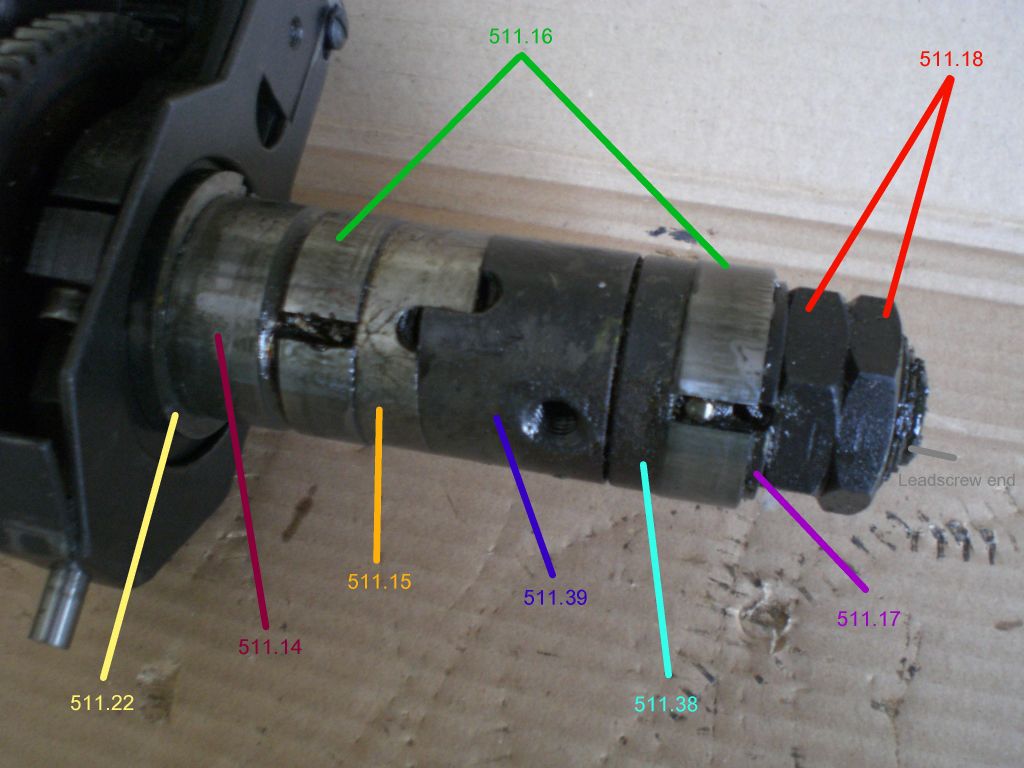
                    Hi all, further to my previous post and inspired by Peter’s photos and various comments by everyone, I’ve had another look at my lathe and studied the pink C210T manual. The operation and explanation of the feed mechanism is not detailed in the Warco manual in so much depth as it is in the pink one. Like Peter I have in the past had this mechanism out, and yes as Peter says keep the leadscrew key and keyway at the top, as it is a very fiddlely job to put the key back into place.

                     
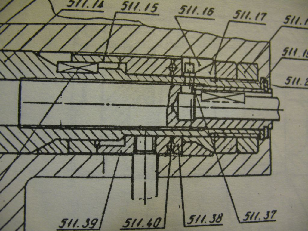
                    I have now found that it is possible to lock the feed lever down and there is no need to hold it, but it takes a little extra effort on the lever to do so. I think Peter’s explanation more or less says it all as to how it all works, so today I studied the pink manual pages E14 and E19 sub tittled The feed mechanism and in conjunction with fig 6 on page E16 and at the same time taking mine out and studying it on the bench. Below is a photo of mine which I’ve labeled with the numbers in the text showing which bits they are talking about.
                     
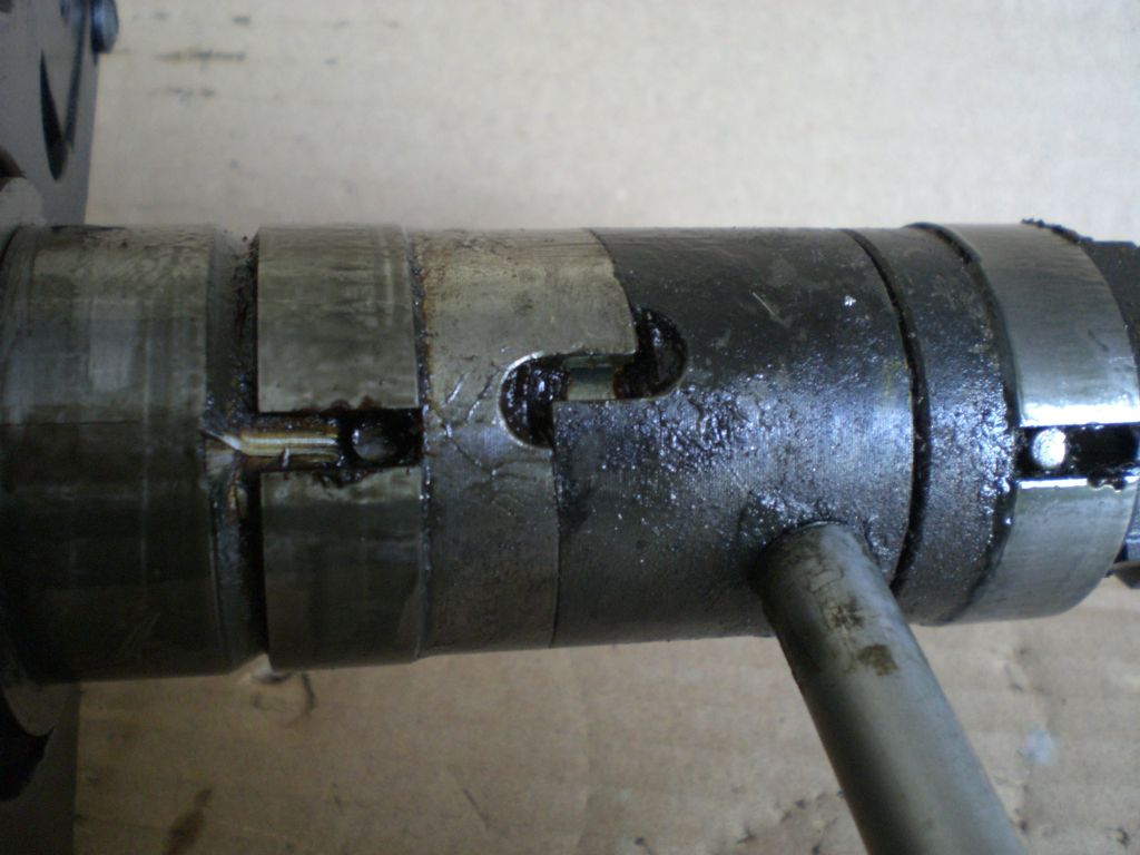
                    This next photo is with the lever turned into the locking position
                     

                    There is another photo in my Warco 220 lathe album which shows inside the housing where this fits, and the end of the leadscrew and the key can be seen. There is also an alternative sectional diagram of the mechanism to that shown on page E16.

                     
                    Like Peter I have not found the screw or pad that Rodger has mentioned.
                     
                    When the lever is in the locked position, it takes more than a flick to release it, so some times it may be easyer just to hold it down when using on a short distance up to a shoulder for instance.
                     
                    Hope this is of some more help to everyone.
                     
                    Regards Nick.

                    Edited By Nicholas Farr on 11/02/2012 18:38:14

                    #84471
                    Peter G. Shaw
                    Participant
                      @peterg-shaw75338
                      Hi Nick,
                       
                      Firstly, congratulations on your photos: they are much clearer than mine.
                       
                      Secondly, I’m interested in two of your comments:
                       
                      “I have now found that it is possible to lock the feed lever down and there is no need to hold it, but it takes a little extra effort on the lever to do so.”
                       
                      and:
                       
                      “When the lever is in the locked position, it takes more than a flick to release it,”
                       
                      What this is saying to me is that maybe my adjustment of the two nuts, 511.18, is not tight enough, hence the expanding cones are not expanding sufficiently to grip the inside of the housing properly thus allowing everything to disengage by itself. Maybe I’ll try tightening it up some more.
                       
                      Regards,
                       
                      Peter
                      #84478
                      Roger Mountain
                      Participant
                        @rogermountain33705
                        Hi Folks,
                        Sorry I have been so long in replying but I have been unsuccessfully battling a front door lock. Many thanks to Peter for his excellent desription of the workings of the auto feed and the accompanying photos.
                        Yes I have had the auto feed out of my lathe and as I recall it was the same as Peter’s apart from the extra grub screw (yes I did lose the key from the lead screw, the parts gremlin shot out from under the bench and made off with it, only returning it after I had filed up a new one from silver steel).
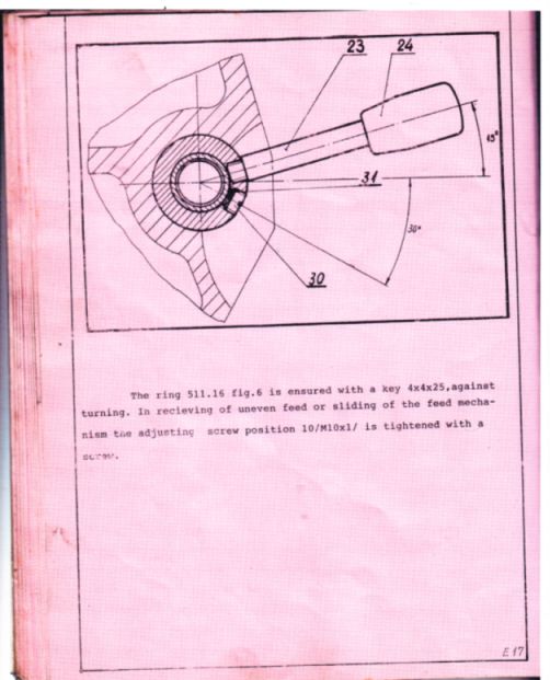
                        The grub screw is threaded into the same cylindrical component as the feed lever it is also shown in the pink manual but the feed lever and the grub screw are transposed.
                        Yes Peter I do have the same gib strips as you, they can be a pain to adjust but once done they don’t seem to need touching for ages. I have drilled and tapped mine M6 in order to accomodate slide locks.

                        As regards jumping out of gear whilst screwcutting this can be avoided by tightening the screw indicated in the above photo, I don’t bother as my lathe has never had this tendency.
                        In order to better lubricate the saddle I have drilled and tapped the front of the saddle for a countersunk M6 screw, this is removed for a few squirts of machine oil every now & again.
                        Just a tip for you Ivy make yourself a wooden bed protector so that when you drop the heavy 4 jaw chuck you don’t mark the bed.
                         
                        Hope this has been of some use,
                         
                        Regards, Roger

                        #84483
                        Nicholas Farr
                        Participant
                          @nicholasfarr14254
                          Hi Peter, thanks for the appreciation of my photo’s, but I think yours a equally as clear as mine, but with my compact Casio Exilim, I can get close shots. It could be that there is too much slack in your mechanism, in the pink manual it says the adjustment should be that the cut rings 511.16 should touch the faces of the nut 511.15 without any play. In the second photo of mine showing it in the locked position, that is as far as I could turn it whilst out of the lathe by holding the fork 511.11 in one hand and the lever in the other and it stayed there without any indication of it slipping back on its own. It was your photos that prompted me to take a more detailed look, so please don’t do yourself down on them, every picture tells a story and helps others. I labeled my first photo for my own benifit as much as anything else to help me understand the text in the pink manual.

                           
                          Roger, I guess your grub screw must be that which is in the detail on page E17, this seems to have no relevance to my lathe.
                           
                          Regards Nick.

                          Edited By Nicholas Farr on 11/02/2012 23:46:08

                          #84508
                          Peter G. Shaw
                          Participant
                            @peterg-shaw75338
                            Roger & Nick,
                             
                            1. My camera is a Canon Powershot A640. Unfortunately, I am/was too lazy to use the tripod. It does have a macro setting, but as yet, I haven’t really worked out the best way to use it. So, my photos tend to be handheld, normal focussing on auto, zoomed in as necessary amd usually with the “unsteady” light flashing away merrily. This is why there is a little bit of blurring on my photos.
                             
                            2. My page E17 is all text. Page E16 does have some diagrams on it, but nothing that I could reasonably consider to be a grub screw. Here’s a photo (macro setting & tripod would you believe) of the relevant part of page E16.
                             

                            This is the only drawing that I have got for this mechanism and does match what exists physically.
                            Final comment re photos. In answer to Roger, I did say that I was uploading at 3Kb. This particular photo was uploaded at 3Mb. I haven’t checked, but I assume the site must reduce the size to suit.
                             
                            Edit: In fact the site says that the photo is 128.71Kb, 1024 x 768 pixels & reduced to 350 x 263 pixels.  The uploaded original was 2816 x 2112 pixels. So some serious reduction there.
                             
                            Regards,
                             
                            Peter

                            Edited By Peter G. Shaw on 12/02/2012 11:37:05

                            #84510
                            Ivy
                            Participant
                              @ivy

                              Post deleted.

                               
                              Sorry my attempts at posting pictures was a dismal failure.

                              Edited By Ivy on 12/02/2012 11:49:58

                              #84513
                              Les Jones 1
                              Participant
                                @lesjones1
                                Hi Ivy,
                                Have a look at the “Wind up torch” thread. There is advice on posting pictures near the end of that thread.
                                 
                                Les.
                                #84515
                                Peter G. Shaw
                                Participant
                                  @peterg-shaw75338
                                  Ivy,
                                   
                                  Here’s my take on uploading photos:
                                   
                                  Take photo.
                                  Transfer to computer. (Should be as a jpg. If not, then run it through a photo editing program to convert it.)
                                  Login to the ME/MEW website.
                                  Go to My Photos.
                                  Create a Photo Album. Give it a name. Then go to Upload Photos and use the Browse function to upload an individual photo (or five). Finally select Upload photos.
                                  Now make any editorial changes you wish.
                                  Finally, go to the thread, eg here, then “Post a reply”. Click somewhere in the box and then click onto the icon second from right. This then allows you to select your album and hence your photo.
                                   
                                  Nick,
                                   
                                  Realised now that you have additional photos in your album – including an alternative line drawing which is exactly mine. This implies you have another drawing of same. Any chance of a look?
                                   
                                  Roger,
                                   
                                  Interested in how you did your slide locks. Did you do it from top to bottom, eg as the three clamp screws? Or did you manage to drill through the this section of the adjustable block? And if so, wouldn’t this lead to weakening the block?
                                   
                                  Thinking now about the screw and pad. Your screw looks to be about 90° round from, and in line with the handle. Correct? Presumably it then bears on the tubular section that everything totates on and has a brass or copper pad between the screw end and this tubular section. Correct? If I’m right, then it should be a very simple modification to do. But I do wonder how new your lathe is, because Ivy seems to imply that she has this adjustment yet her lathe is older than mine. Also, Nick doesn’t have it. So could it be that later lathes don’t have it, or was just a certain batch that didn’t have it?
                                   
                                  I also use a piece of wood to protect the bed: I find the 160mm chuck rather heavy! Not too sure about the additional lubrication though, I use the feed nipple in the middle of the saddle and everything seems to get pretty well covered using H68 type oil. I have though, added a small oil feed hole in the middle of the bracket which holds the cross-slide leadscrew, the isea being to lubricate the bearing below.
                                   
                                  Regards,
                                   
                                  Peter
                                  #84518
                                  Roger Mountain
                                  Participant
                                    @rogermountain33705
                                    Hi Folks,
                                    Here is page E17 from my manual
                                     
                                    Regards, Roger

                                    PS The serial No of my lathe is 084

                                    #84520
                                    Roger Mountain
                                    Participant
                                      @rogermountain33705
                                      Hi Peter,
                                      I did my slide locks by drilling through the adjustable gib block. The lock consisted of an M6 allen screw bearing on to a brass pad cut at 55 degrees bearing on to the dovetail. Yes it must weaken the gib block to a certain degree but they only need to be little more than finger tight to lock the slide.
                                       
                                      Regards, Roger
                                      #84524
                                      Nicholas Farr
                                      Participant
                                        @nicholasfarr14254
                                        Hi Peter, I think the drawing itself is more or less the same, but the numbers are set out differently, which also has other numbers as well. I have scaned page E16 and put it in my Warco 220 album. seems as though there might be a difference in some of the manuals

                                         
                                        Roger, that is the same page that I have in my pink manual.
                                         
                                        My manual says it is factory number 213 and was made in 1993. I don’t know if this coinsides with my lathe or not,because I haven’t ever checked, it just came with the machine when I bought it about six years ago.
                                         
                                        Regards Nick.
                                        #84525
                                        Ivy
                                        Participant
                                          @ivy
                                          OK, lets try again.
                                          Here is my adjusting screw, the same as Rogers.
                                           

                                          I was hoping to go through the adjustment procedure today but I have other problems today.
                                           
                                          Here is a lesson in not using a 3 foot extension bar on your vice handle.
                                           

                                          Pretty impressive for a 9 stone weakling.
                                          That “was” a quality Record No2.
                                           
                                          Actually this is all just an excuse to come into the warm and try to learn posting pictures.
                                          So if it works this time thank you for all the IT help as well as everything else.
                                           
                                          Incidentally I dislike computers with a passion but have to admit the internet is a fantastic resource and brilliant for contacting like minded people.
                                          I better go and do something about that vice now, I have another in the shed somewhere.
                                           
                                          Ivy.


                                          #84554
                                          Peter G. Shaw
                                          Participant
                                            @peterg-shaw75338
                                            Hi all,
                                             
                                            Right, we now have some very useful information.
                                            Starting with serial nos & dates:
                                             
                                            Ulf S/N 080 bought 1992
                                            Roger S/N 084
                                            Ivy S/N089 made 1992
                                            Nick S/N 213 made 1993
                                            Peter S/N 357 made 1994
                                             
                                            A word of explanation: Ulf is a Swedish man I am in occasional contact with and who supplied information on his lathe when I was asking questions all those years ago.
                                             
                                            It would seem that Roger’s lathe, and probably Ulf’s lathe were made in 1992.
                                             
                                            Serial number, on mine at least, is stamped on the right hand end of the bed near the top just above the black (in my case) horizontal bar.
                                             
                                            Drawings.
                                             
                                            Nick’s E16.
                                            My E16 has the three rightmost diagrams and Nick’s alternative diagram. I do not have the left most diagram.
                                             
                                            Roger.
                                            I do not have your diagram re the adjusting screw so thanks for that. Also, thanks for your description of the slide lock. For what it’s worth, Ulf in Sweden did once say that he had dropped a nylon ball down one of the holes followed by a screw and was using that method of locking the cross-slide.
                                             
                                            Ivy,
                                            Wonderful good photo. Thanks for that. Sorry to hear about the vice though!
                                             
                                            Additional comment on the manual.
                                            Some time ago, Ulf sent me a drawing E41 for which he had no information yet it was printed in his manual, but not in mine. He thought it was for a slow speed adaptor, a view with which I eventually agreed after spending some considerable time studying it.
                                             
                                            So, it seems that somewhere between Ivy’s lathe and Nick’s lathe, Mashstroy stopped fitting the screw. I have to wonder why. I think I will email Ulf in Sweden to get his thoughts on it because it seems most likely that he will have the screw.
                                             
                                            Many thanks to all for your thoughts, ideas and information. It goes to show how good ideas can be passed around when people are collaborative..
                                            Regards,
                                             
                                            Peter


                                            #84616
                                            Roger Mountain
                                            Participant
                                              @rogermountain33705
                                              Hi Peter,
                                              The reason I fitted slide locks was that some time ago I had planned to build a longcase clock movement and needed to lock my slides for the wheel cutting, never got round to it but still have the slide locks. I drilled the lubrication hole in the saddle is because my lathe is not fitted with any means of lubricating the saddle without removing the bed wipers.
                                              Ivy, Iam very impressed with the vice, remind not to annoy you.
                                               
                                              Regards, Roger
                                              #84621
                                              Peter G. Shaw
                                              Participant
                                                @peterg-shaw75338
                                                Hi Roger,
                                                 
                                                Understand about the slide locks as it was always a source of concern and wonderment to me that they were not fitted by the manuacturer. I do think that using slide locks could contribute to reducing vibration in some situations, eg milling in the lathe.
                                                 
                                                Re your lack of saddle lubrication. On my lathe, there is a spring loaded ball bearing in a hole on the left hand side of the saddle. This hole is roughly halfway across the bed and halfway between the side of the saddle and the side of the cross-slide. The hole goes right through the saddle hence application of oil under pressure results in a pool of oil on the bed under the saddle which presumably gets spread about by the wipers.
                                                 
                                                I’ll post a photo tomorrow. Can’t do it today as I’m at my daughter’s attempting to improve the lacksadaisical performance of her computer.
                                                 
                                                As an aside, there is an oil hole off-centre in the tailstock for the bearing next to the handle, and an identical spring loaded ball bearing type of oil hole immediately above the thrust washers on the right hand end of the leadscrew. Surprisingly, there are no oil holes for either the cross-slide leadscrew bearing or for the top-slide leadscrew bearing. I’ve added one for the cross-slide.
                                                 
                                                Regards,
                                                 
                                                Peter.
                                                #84739
                                                Peter G. Shaw
                                                Participant
                                                  @peterg-shaw75338
                                                  Roger,
                                                   
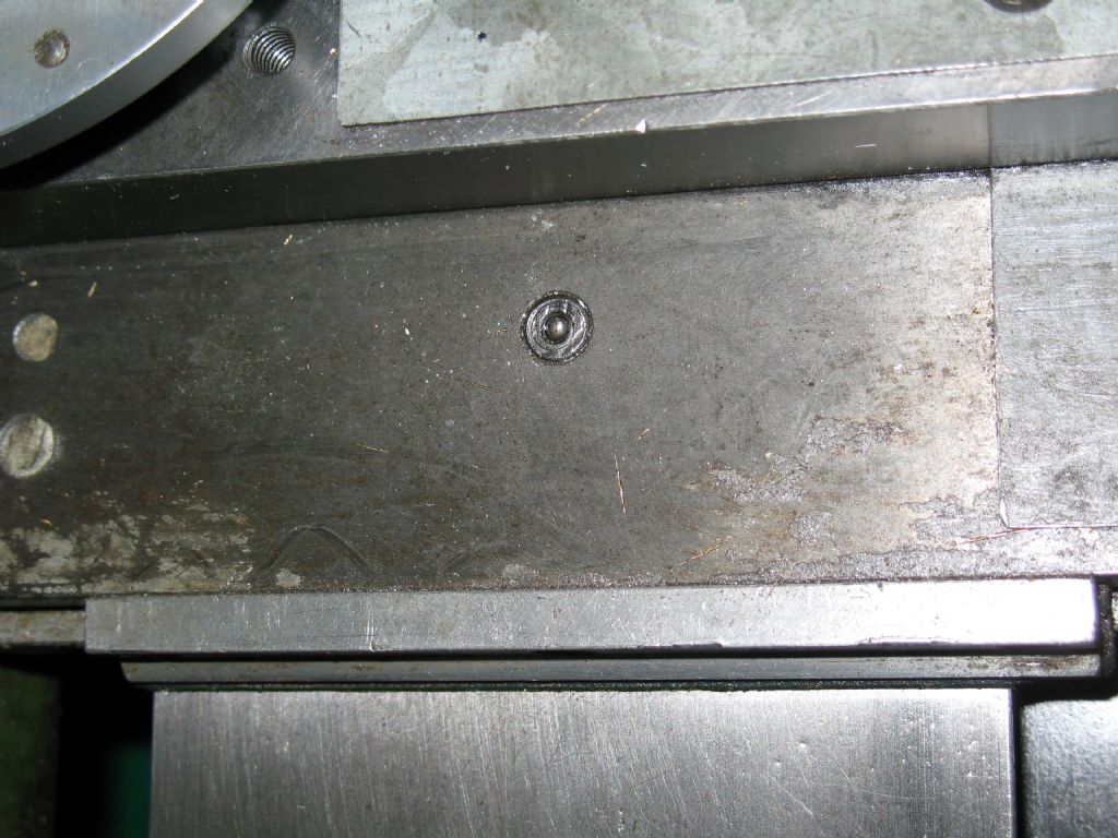
                                                  As promised, here is a photo showing my saddle lubrication point.
                                                   
                                                  For what it’s worth, the two white blobs to the left of the photo are an epoxy putty whilst the grey piece at the right is a piece of metal (steel or ally, don’t know which). What I have done is to block all holes which are either not needed or don’t need to go right through with either epoxy putty, or covered them with a small metal plate. This is to prevent swarf getting where I don’t want it, ie onto the cross-slide dovetails or into the many holes near the apron. Although not shown, I also have a piece of flexible plastic and a bracket to fasten it on the back of the cross-slide and which uses the two rearmost 8mm tapped holes for fastening. The plastic sticks out and slides on the backpanel, the idea being to prevent swarf getting onto the uncovered saddle part of the cross-slide when the cross-slide is being wound towards the front. Photo can be provided if required.
                                                   
                                                  Finally, I have contacted Ulf in Sweden, and he confirms that he also has the adjustment screw and that it does indeed make the handle harder to disengage, but does not seem to affect the engagement. He also confirms that he does have to press the handle down hard to get it to stay down. It is now looking more and more like an alteration to be done to my lathe.
                                                   
                                                  Regards,
                                                   
                                                  Peter G. Shaw
                                                   

                                                  #84766
                                                  Roger Mountain
                                                  Participant
                                                    @rogermountain33705
                                                    Hi Peter,
                                                    Snap, your saddle lubrication point is exacly in the same spot that I drilled mine for a countersunk screw which I remove to lubricate the saddle.
                                                    I don’t have any problem with swarf getting down the screw holes in the cross slide as I normaly run with a home made boring table bolted down to the four theaded holes intended for mounting the vertical slide. This is due to the short length of the cross slide. The other screw hole on top of the saddle I use to mount my swarf tray.
                                                    Looks like you are thinking of fitting the grub screw to your lathe, It seems straight foward, the only probem being finding material for the pad, mine looks like car brake lining material.
                                                     
                                                    Regards, Roger
                                                     
                                                     
                                                    #84769
                                                    Chris Hembry
                                                    Participant
                                                      @chrishembry84309
                                                      Hi Peter,
                                                       
                                                      Been reading this thread with interest as I also have one of these lathes. S/N 129 of 1993. Unfortunately I couldn’t tell you whether it is fitted with the screw or not – will check tomorrow.
                                                       
                                                      Regards, Chris

                                                      Edited By Chris Hembry on 14/02/2012 18:39:43

                                                    Viewing 25 posts - 26 through 50 (of 74 total)
                                                    • Please log in to reply to this topic. Registering is free and easy using the links on the menu at the top of this page.

                                                    Advert

                                                    Latest Replies

                                                    Viewing 25 topics - 1 through 25 (of 25 total)
                                                    Viewing 25 topics - 1 through 25 (of 25 total)

                                                    View full reply list.

                                                    Advert

                                                    Newsletter Sign-up