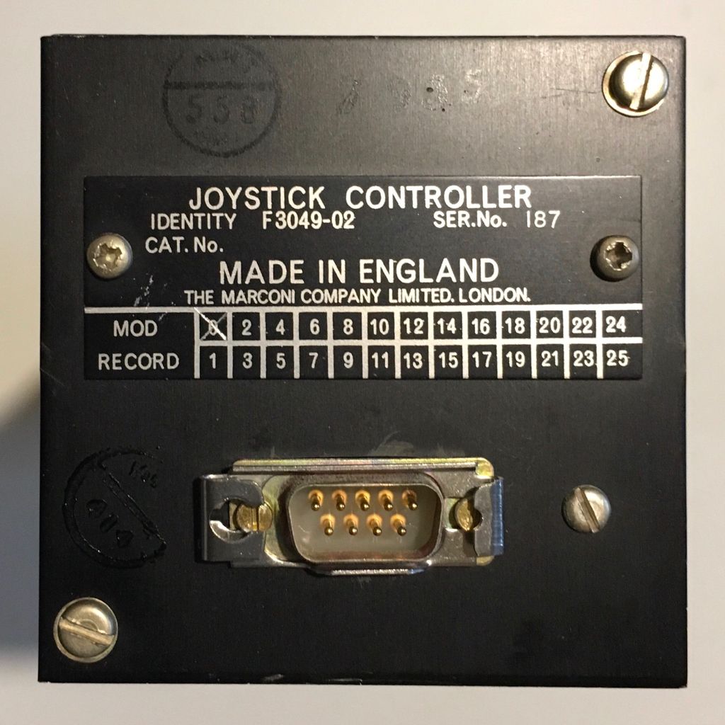
Standard PC joysticks attach to a 15pin D connector on the motherboard or soundcard and consist of a series of variable resistors that are adjusted as the joystick is moved, providing an analogue voltage proportional to position.
The 9 pin connector was found on Atari and similar machines and consisted of switches for up, down, right and left. Software within the computer/console polled these over time to provide positional information. Google Atari joystick pinout for images of the connections.
Without more data it is hard to do more than answer your last question with a no as the connector is not correct. Whether it would work on a games console I can't say, but instinct suggests I would be surprised if it did.
I suggest you try contacting Chelmsford Science and Engineering Society, pretty likely there will an old boy still alive who worked on these. The society has a small museum and doubtless is in contact with Marconi veterans.
I think I know the son of D Gill (in the photo on your link) but rather doubt he would be familiar with that particular piece of kit.
.
Thanks for that suggestion, John … it's certainly worth a try
For info. … I contacted 'marconiradarhistory' yesterday morning [the source of my previous link]
Ian replied very promptly [*] , but it's evident that they are interested in the system rather than the 'bought-in' components.
MichaelG.
.
[*]
Hi Michael,
Thank you for your message.
The Marconi joysticks were made by Specialised Component Division at Billericay. When accurate tracking of radar paints became necessary, joysticks were largely superseded by tracker ball controllers, also made by Specialised Component Division.
Marconi Radar "bought in" the devices as if they were from a third-party supplier – currently we have no need of photographs and I'm not aware of any further detail that might interest you.
regards,
Ian
———————-
This is probably trivial within your sphere of interest, but: Yesterday I purchased an F3049-02 Joystick, in apparently new condition.
The only information I have found, thus far, is linked from your web-page:
Marconi Specialised Component Division also made trackballs. Given the frequent overlap of applications between track balls and joysticks its possible the electronics between the joystick / trackballs and equipment were similar. Although we normally associate joysticks with direction and velocity control they could be used for direct pointer movement like a trackball.
Back in the late 1970's and early 1980's I encountered experimental systems having joysticks of that type at RARDE. As I recall it these were for use in military vehicles. Presumably the idea was that a joystick would be easier to control than a trackball when the vehicle was moving with the inevitable jolts and bumps. No idea who made those joystick but could well have been Marconi.
Cursor Controls **LINK** evolved from the Marconi Trackball division so they may have some knowledge.
I have a vague recollection of seeing a product announcement in an electronics journal that described how Hall effect sensors were used in an industrial joystick. Capacitive and inductive methods are also used in contactless control so without looking inside its anyones guess what you have.
I would be amazed if yours was compatible with analogue PC joystick inputs which nowadays seem to be anyway.
Marconi Specialised Component Division also made trackballs. Given the frequent overlap of applications between track balls and joysticks its possible the electronics between the joystick / trackballs and equipment were similar. [ … ]
Cursor Controls **LINK** evolved from the Marconi Trackball division so they may have some knowledge.
.
Thanks for the note about 'Cursor Controls', Ian … that's useful to know.
As you will see from the eMail response that I quoted earlier: Marconi Radar bought-in the Joystick, and then later the Trackball … That suggests to me that the units may be swappable, and your 'possible' might be elevated to 'probable'.
Useful 'further info' above. The D Gill referred to is my friends Dad but I still doubt my friend will be able to answer the question. (he is a practical chap but didn't work for Marconi)
I will ask a couple of my other 'ex Marconi' friends if they know of the joystick – one worked on computers and the other on military radio communications equipment so might not have ventured into radar area. My uncle worked on radar but more from a mechanical standpoint. As far as I know none worked at the Billericay 'Special Projects' unit but this doesn't mean they didn't come across the joystick in other applications.
Posted by Michael Gilligan on 22/08/2018 23:14:52:
It has a standard 9-pin D 'male' connector on the base panel … but is it compatible with the ordinary, common-or-garden Joystick Port on a PC ?
Highly unlikely. 1977 pre-dates the IBM PC game port by a few years. Also, the way the original PC game port works is quirky(cheap), low resolution, needs frequent re-calibration etc. etc. Not something Marconi would want to be associated with. My guess would be that what you show uses some pins for power input, others for serial position output (RS-232 or relative).
I am going to disagree with Nick Clarke here. A PC joystick has just the variable resistors, the rest of the circuit is on the sound/game card **LINK**. BBC Micro joysticks did output analogue voltages.
Useful 'further info' above. The D Gill referred to is indeed my friends Dad but I still doubt my friend will be able to answer the question. (he is a practical chap but didn't work for Marconi)
My uncle worked on radar but more from a mechanical standpoint and whilst he has some knowledge of the trackball (ball made by a maker of snooker balls!) and is aware of the joystick as used for anti aircraft missiles (using radar tracking) he does not know anyone involved with the electronics of that.
I will ask a couple of my other 'ex Marconi' friends if they know of the joystick – one worked on computers and the other on military radio communications equipment so might not have ventured into radar area. As far as I know neither of my fiends worked at the Billericay 'Special Projects' unit but this doesn't mean they didn't come across the joystick in other applications or know an electronics colleague who worked at Billericay. I will speak to them and find out if they have a lead for you.
D connectors were invented years before the IBM-PC made them commonplace, I think in the 1950s. At various times I've come across about a dozen sizes in surplus equipment and at work, 9 pins being the smallest up to a beast with 60 or 70 pins. They're used in computers, military electronics and instrumentation.
As the military had joysticks before WW2 it might be worth searching for a relevant Def Stan or MilSpec.
In the late '70s an RS232 connection would only have been D25, not D9. I think as the article mentioned avoiding the use of potentiometers it was most likely using synchros, certainly would have been my choice then as they were used for a lot of precision positional feedback, eg in avionics. It doesn't look like a GEC format part No and we didn't call things 'identity' it would have a Drg (drawing) or NSN (Nato Stock No). Since the article also mentions a circulator with a part No beginning with F it could perhaps have been made at Frimley.
I was at Stanmore then, a completely different division, as Marconi Space and Defence Systems. It's an housing estate now
I may be way off the mark here but the absence of a nato stock number (NSN) would indicate that it wasn't a military item. By 1977 anything that moved or could be removed would have had an NSN.
The 'D' connector only having an sliding retainer would also indicate that it wouldn't have been used on anything military that moved. They would have used screw retainers and in serious applications wire lock them. Then again an Amphenol type socket would have been used.
So with the circulator a civilian ground radar system?
(Just noticed that Bazyle has said much the same thing, but then we did work at Stanmore at the same time…)
Not quite solid state but how about two strain gauges in the X and Y axis? Does the joystick move much? I can't recall what system it was related to but I remember a joystick system, from about the same era, that had limited movement in the X/Y axis.
If it does use strain gauges, and assuming no amplifiers in the way, it would be easy to identify the two Wheatstone bridges with a meter. It would only need 6 pins for two bridges. One other for ground shield and the remaining two for the non existant push button switch(es)
Take the lid off and a photo of the internals would be helpfull
That MoD identification label is an awfully familiar style. Although NATO stock numbers were officially universal from mid to late 1970's in practice much of the kit I saw at RARDE up until the mid 1980's when I stopped having regular contact with direct from the military equipment made do with a simple MoD plate of that style.
Field and deployable equipment always got the NATO number. But fixed base, experimental and modified equipment frequently did not. Seemed to me that you could only be certain of finding NATO numbers on general issue equipment. Experimental and research et al kit, which was what I mostly dealt with, supplied via MoD made do with that sort of plate.
I may be way off the mark here but the absence of a nato stock number (NSN) would indicate that it wasn't a military item. By 1977 anything that moved or could be removed would have had an NSN.
.
Not off the mark at all
The unit I have is built to very high standards, but it appears to be a commercial item … it is not ruggedised for field use, and has no NSN [that was the first thing I looked for].
.
As I have already stated, I don't wish to start dismantling it … I did lift the lid, just far enough to see that all the leads to the D connector are pink, and have tiny heat-shrink identifiers. The back of a glass-fibre circuit board is visible, and the leads pass through clearance holes in the board. …. Any further investigation from that side would almost certainly involve damaging the original assembly detail [which I want to preserve].
I am, for the moment, treating this unit as a rare historic artefact.
If no information is forthcoming, I may try dismantling via the top plate; but that again seems likely to ruin the integrity of the original construction.