Making small helical gear(s)

Advert

Making small helical gear(s)

Home Forums Beginners questions Making small helical gear(s)

Viewing 25 posts - 26 through 50 (of 80 total)
  • Author
    Posts
  • #239837
    Dave Smith the 16th
    Participant
      @davesmiththe16th

      Seat motor, its in the waffle above, so a slow speed and the original gear was plastic (nylon)? So an aluminium or brass one maybe stronger?

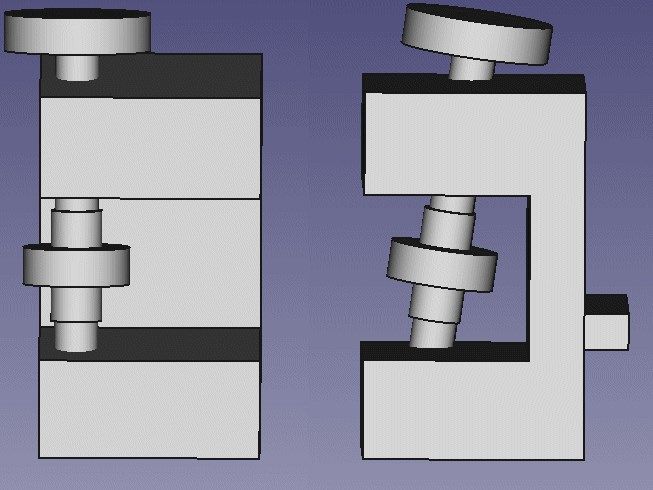
      Something simple like this? gear cutter.jpg

      This is 8 degrees and should mount in the lathe easily. Could do with a method of moving it up and down though to get a full width cut, or is that not needed as long as the cutter is a larger diameter than the drive gear?

      3D print the top with 20 holes to use to index the gear?

      Can you see anything wrong with this setup? Anything even easier?

      Lay it down and make it on the mill instead to get a full cut using the table travel?

      Advert
      #239846
      Michael Gilligan
      Participant
        @michaelgilligan61133
        Posted by Dave Smith the 16th on 23/05/2016 02:53:11:

        … The gear measured 28.9mm so its close enough. 5% angle maybe a bit borderline though. Maybe 8 – 10%?

        … The original gear is plastic (nylon)? So swapping it out to aluminium, could i use a straight tooth instead? Its a slow motor thats used infrequently in its application. (seat motor if thats of any use)?

        .

        Dave,

        From your description; it seems that this might actually be a simple skew cut gear acting as a wormwheel … am I correct? … A good picture of the original device might be worth the proverbial thousand words.

        MichaelG.

        #239849
        JasonB
        Moderator
          @jasonb

          Dave is this a parallel gear eg where both gears are in the same plane (sounds likely by the shallow angle) or is it a right angled pair of gears that change the direction of rotation?

          That link to HPC I posted earlier was for parallel helical gears as they fitted your size.

          Edited By JasonB on 23/05/2016 07:39:20

          #239861
          Michael Gilligan
          Participant
            @michaelgilligan61133
            Posted by Neil Wyatt on 22/05/2016 18:55:52:

            Saw a great device at Harrogate that apparently was described in ME some years ago.

            .

            It gets a mention here

            … worth a look.

            MichaelG.

            #239864
            Anonymous
              Posted by Dave Smith the 16th on 23/05/2016 02:53:11:

              When hobbing a gear does it space the teeth correctly when taking the initials cuts? Thinking out aloud.. The tool is approx 1mm further away from its final cutting position. Wont that try to cut an extra tooth or so?

              I watched the Myfordboy video and he precut the teeth on a gear, for that reason?

              In normal hobbing the gear blank and the hob are geared together. In the gear sizes we're talking the hob would be cutting full depth in one pass. So there is no need to precut, nor will there be an extra tooth.

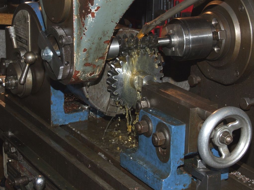
              For free hobbing, where the hob drives the work, then gashing the blank beforehand is necessary, as was this worm wheel:

              worm wheel hobbing.jpg

              Andrew

              #239867
              Tim Stevens
              Participant
                @timstevens64731

                It seems to me that cutting a helical gear on a 'simple' home mill could be done using toothed belts.

                Fit a toothed pulley on the end of the x lead-screw, with a belt driving a pulley above it but carried on a shaft which is angled to align with the intended teeth. The distance apart would need to be fairly large, and it might need a guide to keep the belt running true.

                This shaft then drives the work on a spindle set at the same angle, and fixed to the table. The gearing would need to be chosen to match the required angle. A cutter would be carried with the mandrel vertical, and would be shaped like a large engraving cutter. As the x traverse handle is turned, the work would rotate (because of the gearing) and move the workpiece under the tool to cut a single toothspace. The spindle would also carry a dividing plate with holes to match the number of teeth, and so, each tooth space could be cut in turn.

                An alternative scheme would use a conventional gear cutter, carried in a mandrel set at the tooth angle, and alongside the workpiece rather than above it. Then a twisted belt would not be needed.

                Is either of these notions new, and/or possible, and/or worth following up with a test run?

                Regards, Tim

                #239875
                Anonymous

                  I don't know about the toothed belt, but the concept of using a formed end mill style cutter isn't new. It is discussed in a book I have on spiral and worm gears written in 1914.

                  Andrew

                  #239876
                  Tim Stevens
                  Participant
                    @timstevens64731

                    Hello Andrew

                    No, it isn't new, but then, almost everything we do has been done before. I only ask if the idea of toothed belts has been applied in this way to turn the work as the table moves. If it has, what problems arose, and how solved?

                    Cheers, Tim

                    Edited By Tim Stevens on 23/05/2016 11:31:35

                    #239899
                    Dave Smith the 16th
                    Participant
                      @davesmiththe16th

                      Jason its a right angled setup, the worm is 90 degrees to the gear. Similar to Andrews picture above.

                      There is a hub on both sides of the gear also, i didnt find anything suitable on the HPC site. did i miss it?

                      Free hobbing, shows where a lot of youtube videos are misleading. Quite a few are free hobbing with no initial cutting of the teeth.

                      Anyone see any issues with my little frame above for holding the gear? If using the lathe i thought use the toolholder height adjustment to get a full cut if needed.

                      Index the top disc for 20 teeth. Or use the mill and feed across for a full cut. From what i have seen so far though a cutter slightly bigger than the worm should give enough tooth clearance anyway?

                      Not ideal but it should work if a little time consuming? yes?

                      Thanks.

                      #239901
                      JasonB
                      Moderator
                        @jasonb

                        So its a worm and wheel you need not helical/skew gears.

                        Or are you confusing a worm with a steeply helixed helical gear as it is possible to have 17deg/77deg skew/helical gear pair but neither would be called a worm.

                        Can you post a picture of the two gears in question as it may save a lot of wasted time.

                        If you look at the two gears here you will see one is 20degrees and the other 70degrees, both are skew gears, neither a worm but they are a mating pair of 2:1 gears


                        Edited By JasonB on 23/05/2016 15:43:30

                        #239911
                        Dave Smith the 16th
                        Participant
                          @davesmiththe16th

                          100% a worm.

                          #239914
                          Jens Eirik Skogstad 1
                          Participant
                            @jenseirikskogstad1

                            Posted by Dave Smith the 16th on 23/05/2016 17:00:27:

                            100% a worm.


                            Use lathe to create the worm same manner as you are making the bolt with treads. Take 40 degree tool and set topslide to 20 degree, then "tread" up the worm from blank to a ready worm. Module 1 is same as 3.14 mm pitch between wormgear teeth, if you want 1.5 module = 3,14 mm x M 1,5 = 4,71 mm pitch , also calculate the pitch/leadscrew ratio and set up the gear set to make required pitch.

                            To calculate worm, wormgear —> **LINK**

                            Edited By Jens Eirik Skogstad on 23/05/2016 18:00:29

                            #239940
                            Anonymous
                              Posted by Dave Smith the 16th on 23/05/2016 15:31:31:

                              Free hobbing, shows where a lot of youtube videos are misleading. Quite a few are free hobbing with no initial cutting of the teeth.

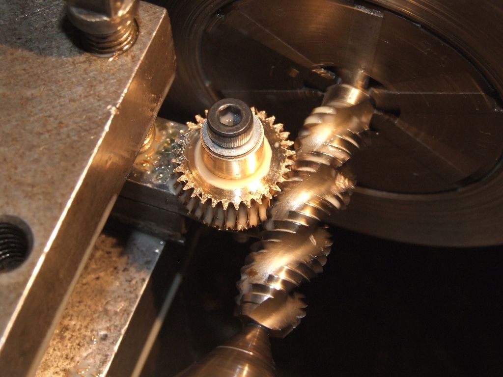
                              There's nothing wrong with that; provided you're not overly worried about the exact number of teeth. In the picture below I didn't care how many teeth there were, just that the PCD was somewhere about right:

                              hobbing worm wheel me.jpg

                              The worm wheel is for the adjustment of the governor on my traction engine. To save time the 'hob' is a 7/16" UNC spiral flute tap, bought on Ebay.

                              Andrew

                              #239949
                              Dave Smith the 16th
                              Participant
                                @davesmiththe16th

                                With my luck it will probably churn away the entire blank and leave no teeth until its too small for the task.

                                I need to make a tool to match the gear and then make a holder for it also. DIY flycutter? Or something else?

                                Myfordboy made an onvolute cutter using little button cutters. So many tasks to do before i can actually cut a gear.

                                I will have to make an indexer also. Any tried printing one with an inkjet? How accurate? I think i need to be more accurate than my nearest couple of mm

                                The above picture gave me a better and more compact idea, just need to index it and clamp it..

                                Thanks.

                                #239954
                                Michael Gilligan
                                Participant
                                  @michaelgilligan61133
                                  Posted by Dave Smith the 16th on 23/05/2016 20:49:22:

                                  I will have to make an indexer also. Any tried printing one with an inkjet? How accurate? I think i need to be more accurate than my nearest couple of mm

                                  .

                                  See the link I posted on on this thread.

                                  MichaelG.

                                  #239980
                                  Dave Smith the 16th
                                  Participant
                                    @davesmiththe16th

                                    Excellent, Many Thanks.

                                    I measured the worm with my thread gauges and its not quite a 4.0. I didnt try the metric or whitworth ones.

                                    And my quest for help is here again, Myfordboy (youtube) mentioned info on the button sizes for making buttons to create a involute gear cutter. Is this info available online?

                                    Thanks again.

                                    #239981
                                    Hopper
                                    Participant
                                      @hopper

                                      A printed indexer is not going to be very accurate for gear cutting, unless you make it about 6 inches diameter or more.

                                      A traditional alternative is to use another 20 tooth (or multiple of) gear attached to the other end of the shaft that the gear blank is mounted on. A simple plunger engaging between the teeth of the gear provides nice accurate indexing. Any sized gear of the right number of teeth (20, 40, 60 etc) will do the job. Lathe change gears are the common choice.

                                      As it turns out you are looking at making a gear to mate with a worm on a low rpm, low power, infrequent use application, you can probably get away with using a spur gear rather than a hobbed worm. You just need to cut the teeth on the spur gear at the correct angle to match the worm. This will depend on the helix angle on the worm itself, which will depend on the diameter of the worm. For example, a 20DP worm of .750" diameter will have a helix angle of about 4.5 degrees.

                                      So if the 20DP-compatable worm is meshed with a straight cut spur gear, the worm will have to be mounted at a 4.5 (approx) degree angle to get full depth of tooth engagement.

                                      Or, alternatively, you can machine your spur gear in the conventional manner but with the blank mounted at a 4.5 degree angle to the cutter. This will cut a spur gear with the slightly angled teeth.

                                      Another alternative is to simply use a straight cut gear and thin down the teeth on the worm to allow the 4.5 degrees or rotation to bring the worm back into staraight alignment.

                                      Yes, these are bodges but will work on low power, low revolution, low useage applications. The worm on spur gear combination gives only point contact, whereas a properly cut wormwheel gives line contact so wears better in high load, continuous use applications.

                                      As you have just bought a milling machine, you will obviously be coming up against more of this stuff as time progresses. I'd highly recommend you spend the small amount of cash needed to buy two books from the Workshop Practice series, "Gears and Gear Cutting" by Ivan Law and "Dividing" by Harold Hall. These are essential reading for getting started on this stuff. They are small, simply written, well illustrated books that contain most of what you will even need to know on the subject. They will enable you to get so much more out of your new milling machine.

                                      George H Thomas's two books, "Model Engineers Workshop Manual" and "Workshop Techniques" are also a treasure trove of info on this stuff, but considerably more pricey.

                                      #239982
                                      Dave Smith the 16th
                                      Participant
                                        @davesmiththe16th

                                        Getting the mill Tuesday ( today now, oops i need my bed )

                                        Dividing heads etc are all on my wish list, but when your poor and have far too many hobbies some things have to wait. I blame the missus, she keeps taking the money for something called bills?

                                        I have no idea who this bill is but he is expensive to keep

                                        Yeah i have a 40, 60 and 80 teeth change gears to use, not sure on the 20? I cannot take the worm out without serious pain. Its pressed into a housing and may not fit back snugly without more work.

                                        Now i know why people charge so much for these gears.

                                        Next step is howto secure the gear onto the shaft? I presume the original plastic gear was fitted to a hot shaft or expanded/shrunk when fitting?

                                        Add a grub screw or roll pin or tight fit and glue it on?

                                        Turning into something bigger than i imagined.

                                        Thanks for the help.

                                        #239983
                                        Hopper
                                        Participant
                                          @hopper

                                          Make your own dividing head. Very simple to make one using change gears for indexing. Harold Hall's book on dividing I mentioned above has all the details on how to do it. A good beginner project on the milling machine! And then a simple job to turn up a matching worm and make some drilled division plates.

                                          GH Thomas's book "Workshop Techniques" mentioned above has all drawings and instructions for making the ultimate home dividing head the "Verstatile Dividing Head" with a double worm arrangement that gives indexing resolution of 1/1000 of a degree. Probably a bit over the top but a very nice project.

                                          Loctite might hold the gear for you. Or if the blank has a boss on the side of the gear, drill and pin and Loctite. I would avoid grubscrews. They tend to work loose over time. Pin and loctite are set and forget.

                                          #239985
                                          Hopper
                                          Participant
                                            @hopper

                                            Harold Hall's simple dividing head, suitable for gear cutting, and suitable to add a homemade worm and index hole plates to for further refinement at a later date:

                                            #240085
                                            Martin Newbold
                                            Participant
                                              @martinnewbold

                                              Wow Jens , that is impressive video on what looks like a drill love this kit you have .

                                              Edited By Martin Newbold on 24/05/2016 18:08:22

                                              #240103
                                              Nigel McBurney 1
                                              Participant
                                                @nigelmcburney1

                                                Just a thought would a Meccano worm and straight cut worm wheel do the job,Meccano worm wheels could be either the narrow width gear wheels or the wider brass pinions,all of these STRAIGHT cut gears meshed with the worm and very often ran at Meccano motor shaft speed to get a good initial gearing down of the motor shaft,the shafts ran at right angles without a problem.Not good engineering but they worked and worked well ,and it proved that at low powers there was no need for fancy theories and the teeth cut at an angle. plus Meccano gears are not expensive .

                                                #240106
                                                Dave Smith the 16th
                                                Participant
                                                  @davesmiththe16th

                                                  I think i get the dividing head now. (i think)


                                                  60 tooth gear, 1 turn on the worm = 6 degrees and it moves one tooth. 60 turns for a full circle.

                                                  I think this is right.. If the index plate had 6 holes then you could accurately turn the gear in 1 degree increments. If it had 60 you could get 0.1 accuracy?


                                                  Have you taught me something?


                                                  Meccano gears wont work because the gear needs a hub on both sides and that hub is shaped to fit into a housing.  The worm/screw is the same shaft as the motor so changing that it not an option either.

                                                  I think the straight cut gears may well be the way.  The original gear was plastic/nylon? so an aluminium one should be better (maybe?).


                                                  Thanks


                                                  Edited By Dave Smith the 16th on 24/05/2016 19:49:18

                                                  #240114
                                                  Jens Eirik Skogstad 1
                                                  Participant
                                                    @jenseirikskogstad1
                                                    Posted by Dave Smith the 16th on 24/05/2016 19:45:39:

                                                    I think i get the dividing head now. (i think)

                                                    60 tooth gear, 1 turn on the worm = 6 degrees and it moves one tooth. 60 turns for a full circle.

                                                    I think this is right.. If the index plate had 6 holes then you could accurately turn the gear in 1 degree increments. If it had 60 you could get 0.1 accuracy?

                                                    Have you taught me something?

                                                    Follow this link how to use indexing head..

                                                    **LINK**

                                                    #240204
                                                    Neil Wyatt
                                                    Moderator
                                                      @neilwyatt

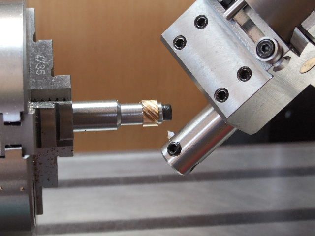
                                                      Graham Meek sent me a picture that shows an unusual approach to approximating a helical gear:

                                                      brass 14t 0.5 mod crossed helical gear.jpg

                                                    Viewing 25 posts - 26 through 50 (of 80 total)
                                                    • Please log in to reply to this topic. Registering is free and easy using the links on the menu at the top of this page.

                                                    Advert

                                                    Latest Replies

                                                    Home Forums Beginners questions Topics

                                                    Viewing 25 topics - 1 through 25 (of 25 total)
                                                    Viewing 25 topics - 1 through 25 (of 25 total)

                                                    View full reply list.

                                                    Advert

                                                    Newsletter Sign-up