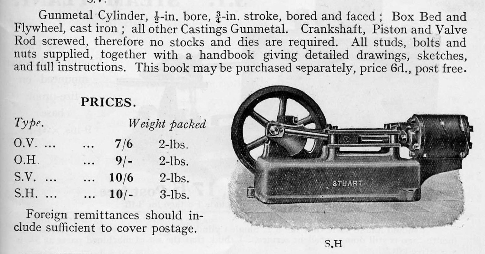
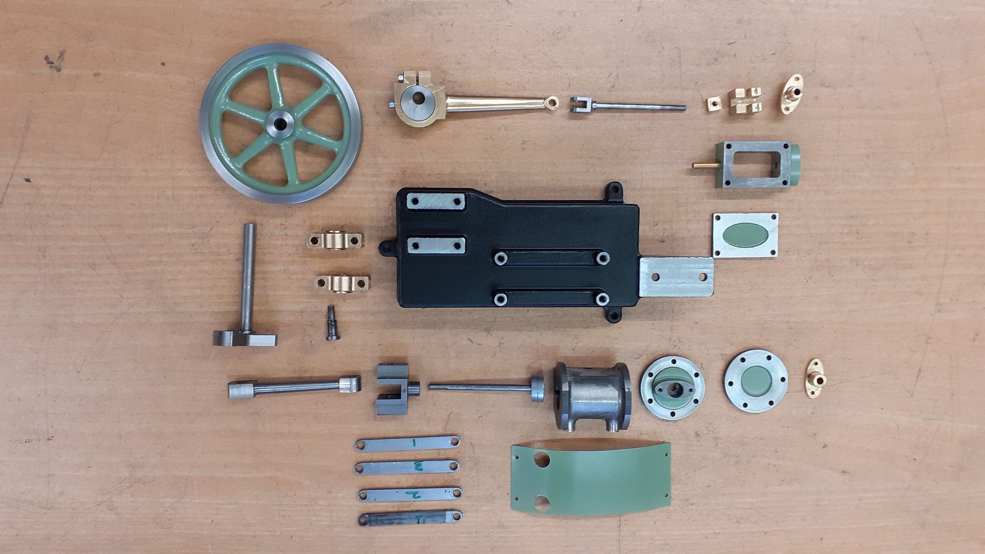
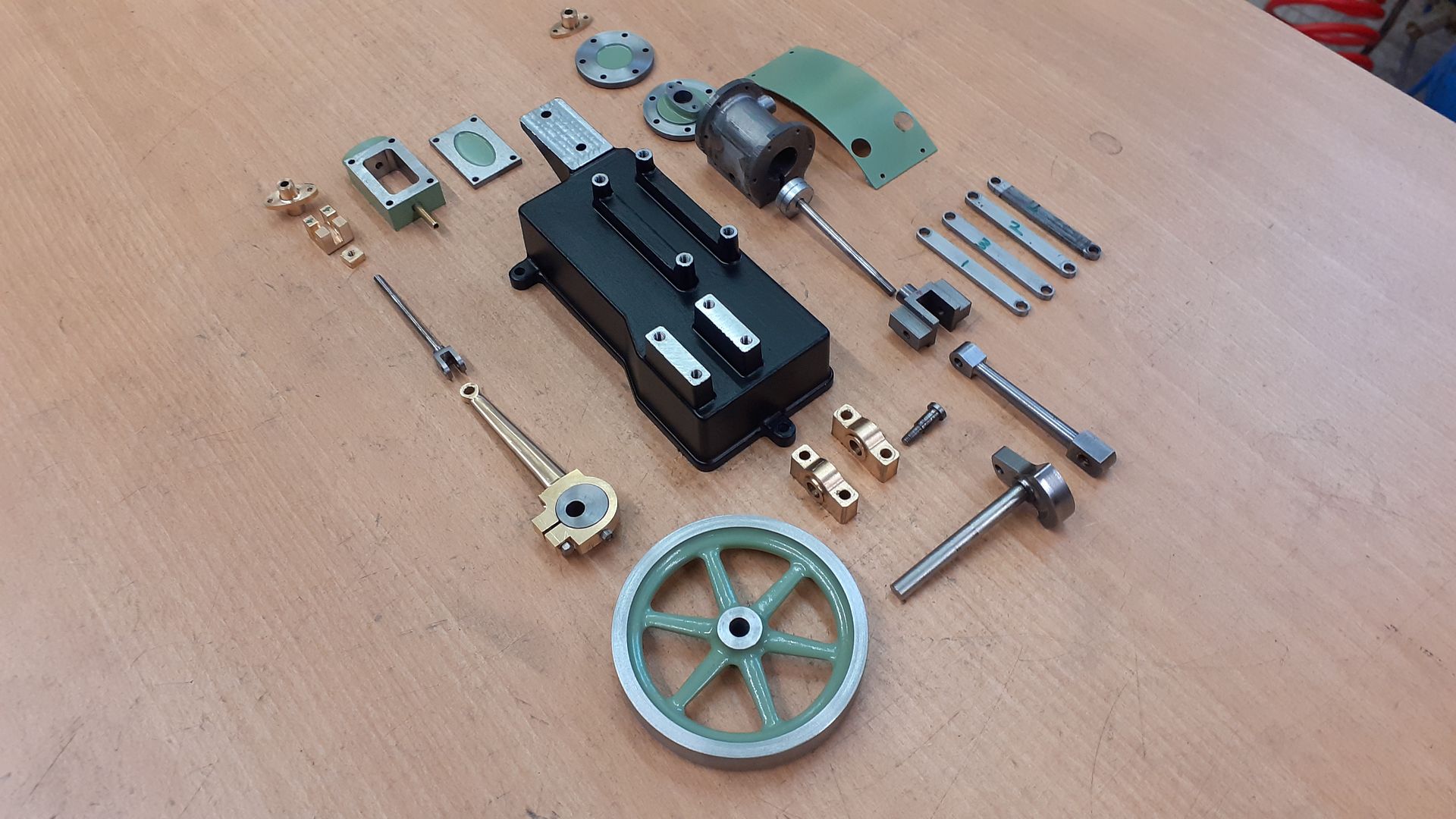
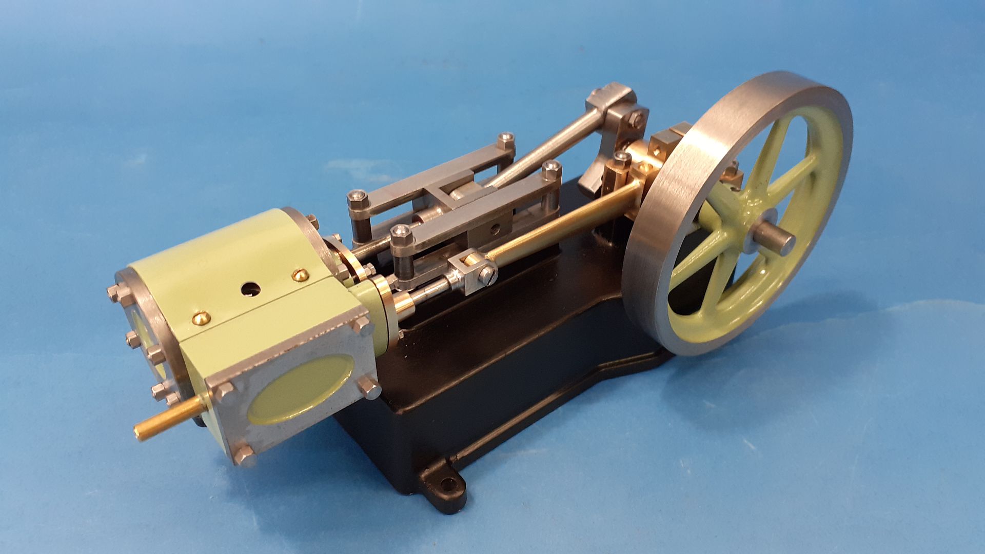
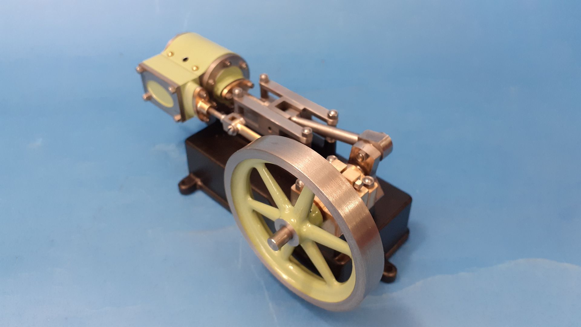
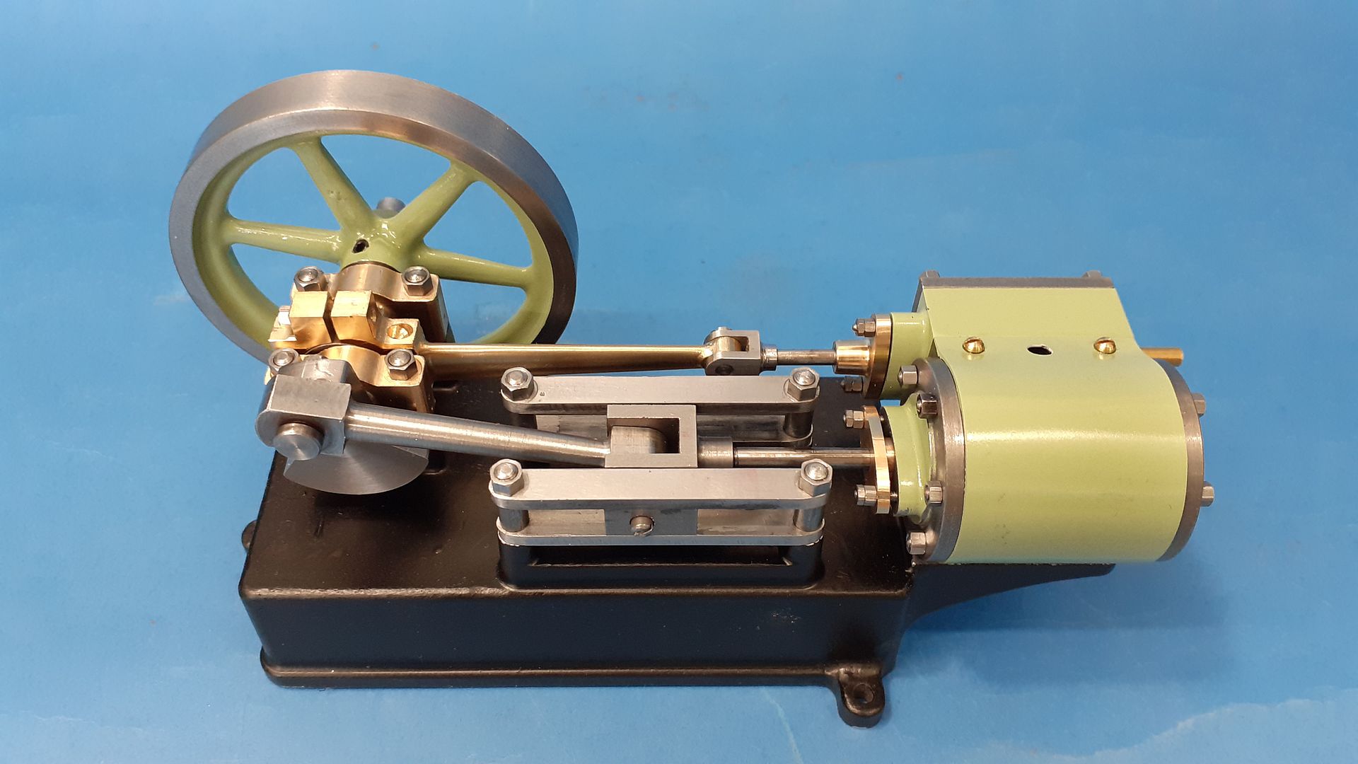
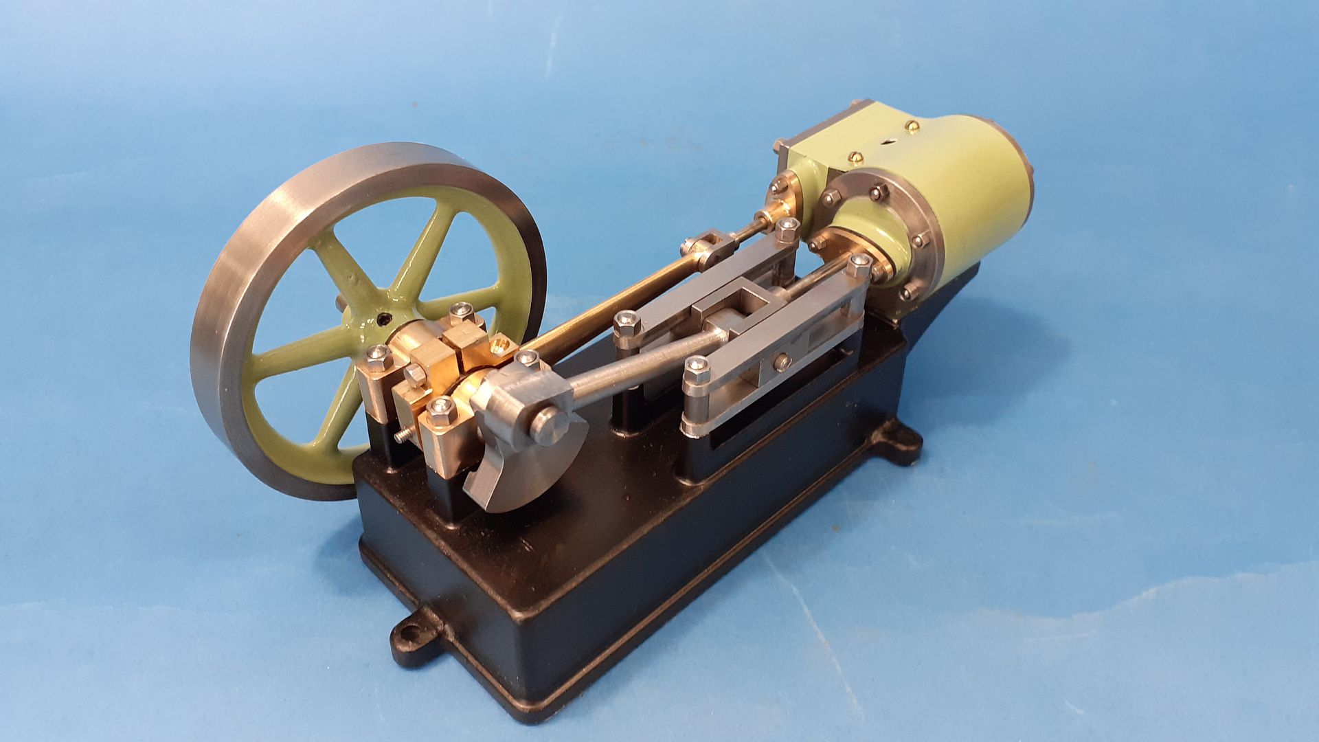
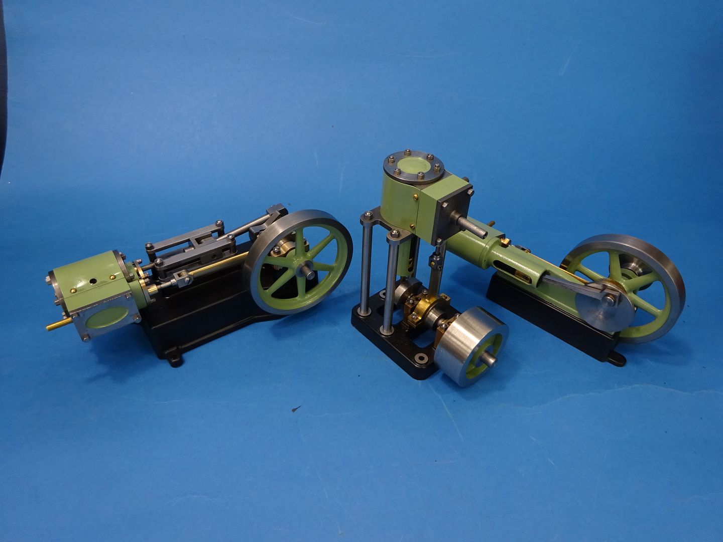
Or more precisely a replica of the Stuart Models "Progress SH"
99 years ago in 1924 Stuart introduced the "progress" range of six engines all sharing a similar bore and stroke and consisting of horizontal and vertical oscillators, horizontal and vertical slide valve engines, a mill engine and an undertype engine. Production ran up until about 1941 with only the horizontal oscillator being reintroduced a few years ago.
The subject of this thread is the Progress SH standing for Slide valve Horizontal an engine of similar style to the well known S50 with a bore of 1/2" and a stroke of 3/4"

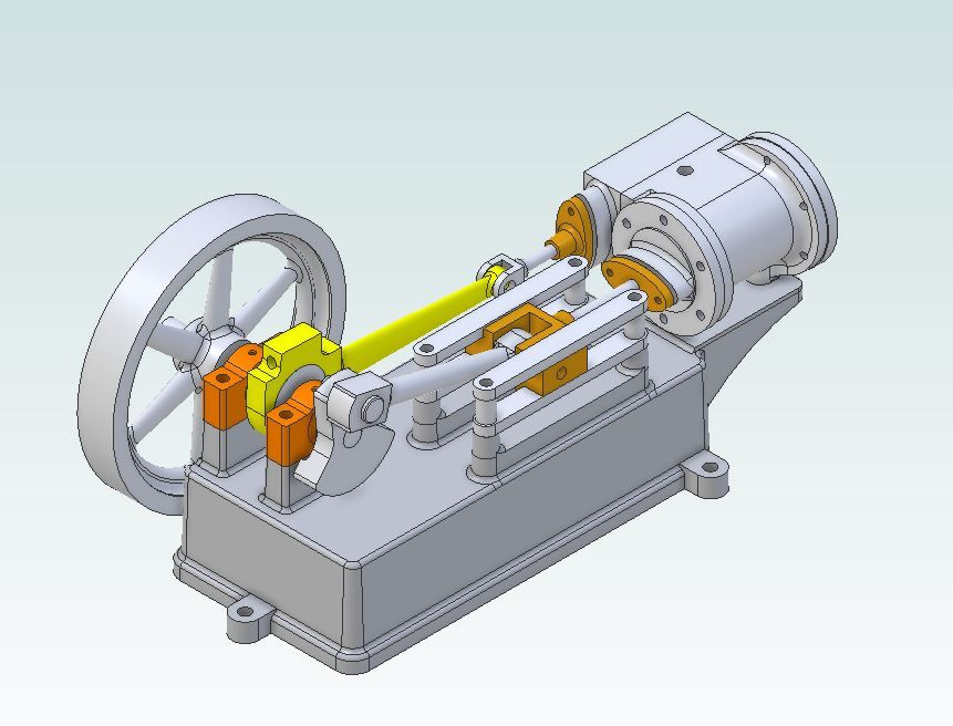
A reprint of the booklet mentioned in the above catalogue extract is still available from Tee Publishing and covers all the engines in the range with building notes as well as drawings so that is what I started with. As with my other recreations of long lost small engines I set to and redrew it in metric with a 12mm bore and 20mm stroke in Alibre, exporting some parts to F360 to make use of the CAM function to generate the G-code needed for the CNC mill.

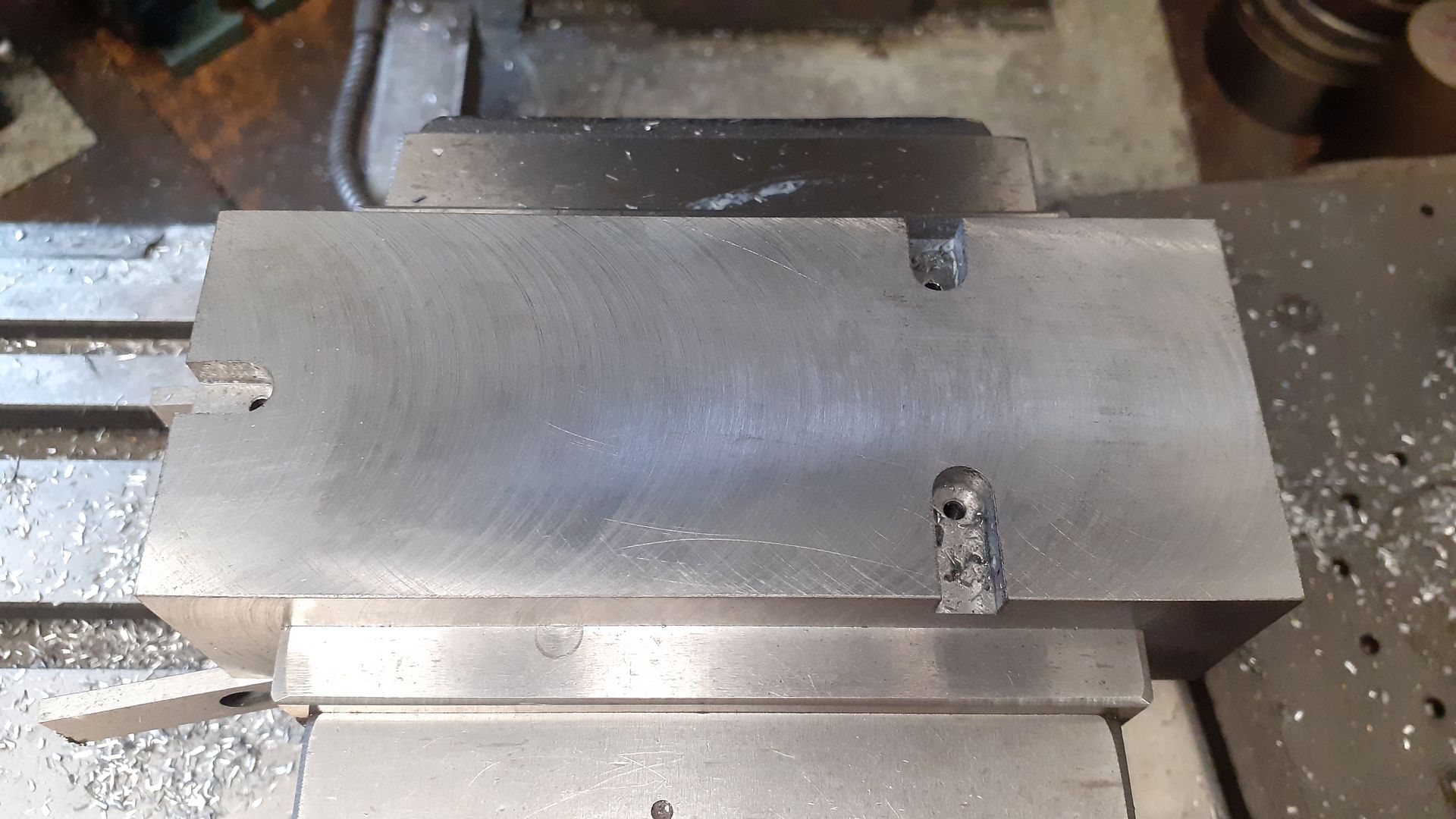
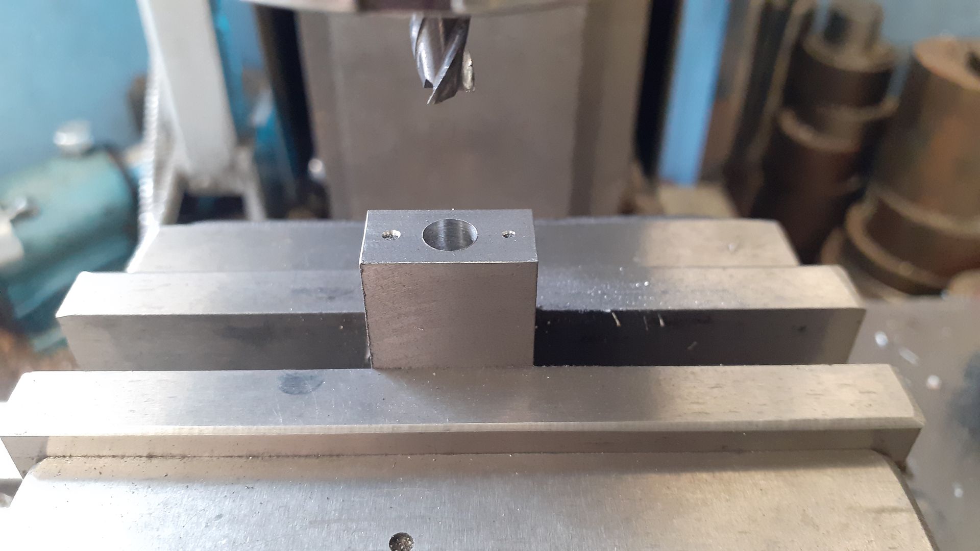
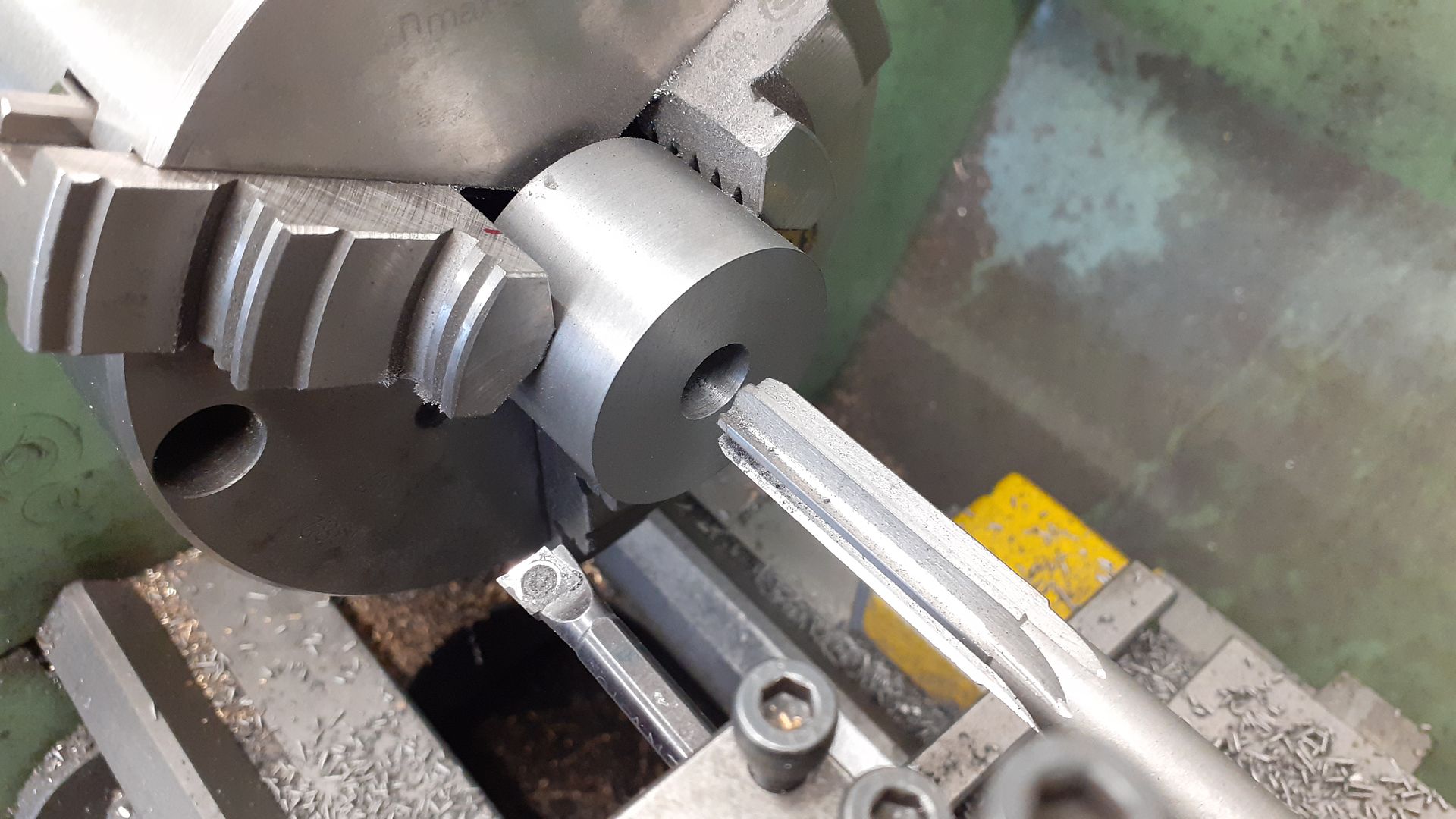
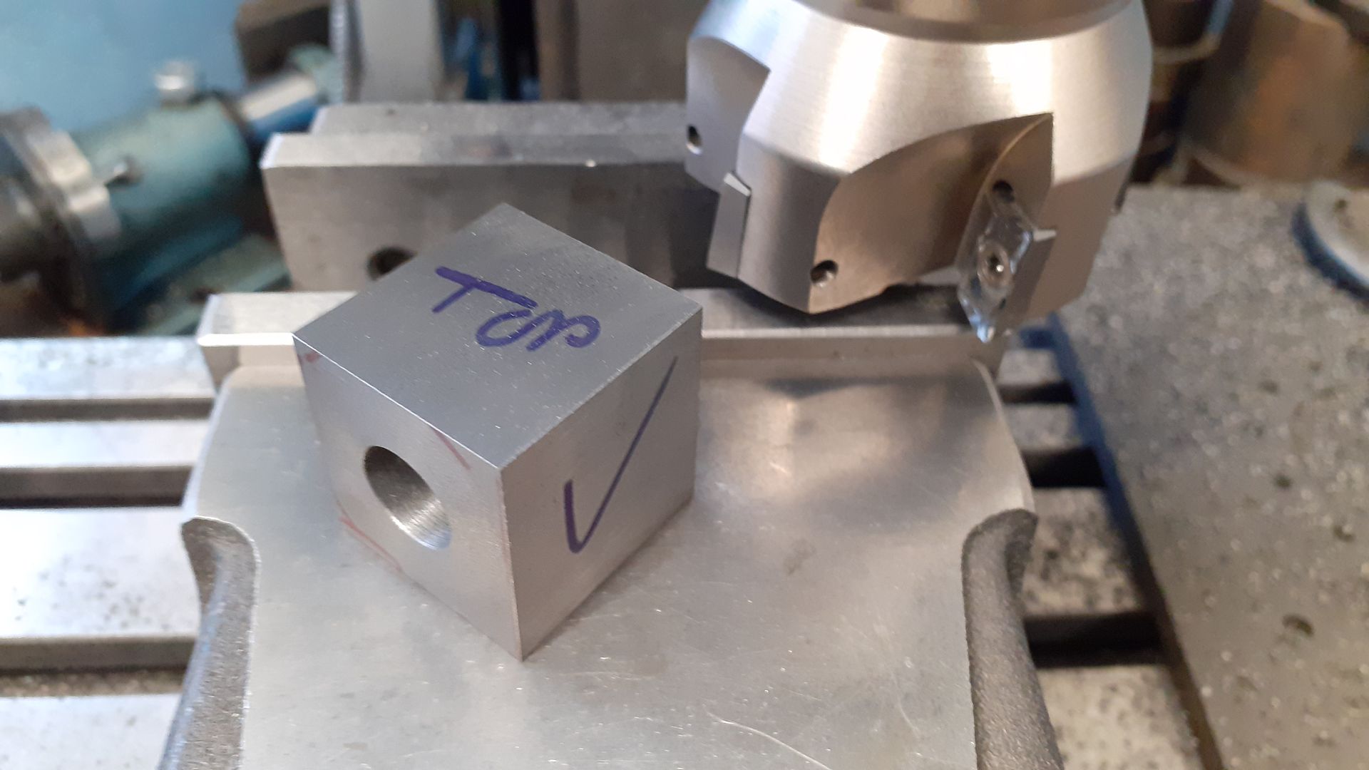
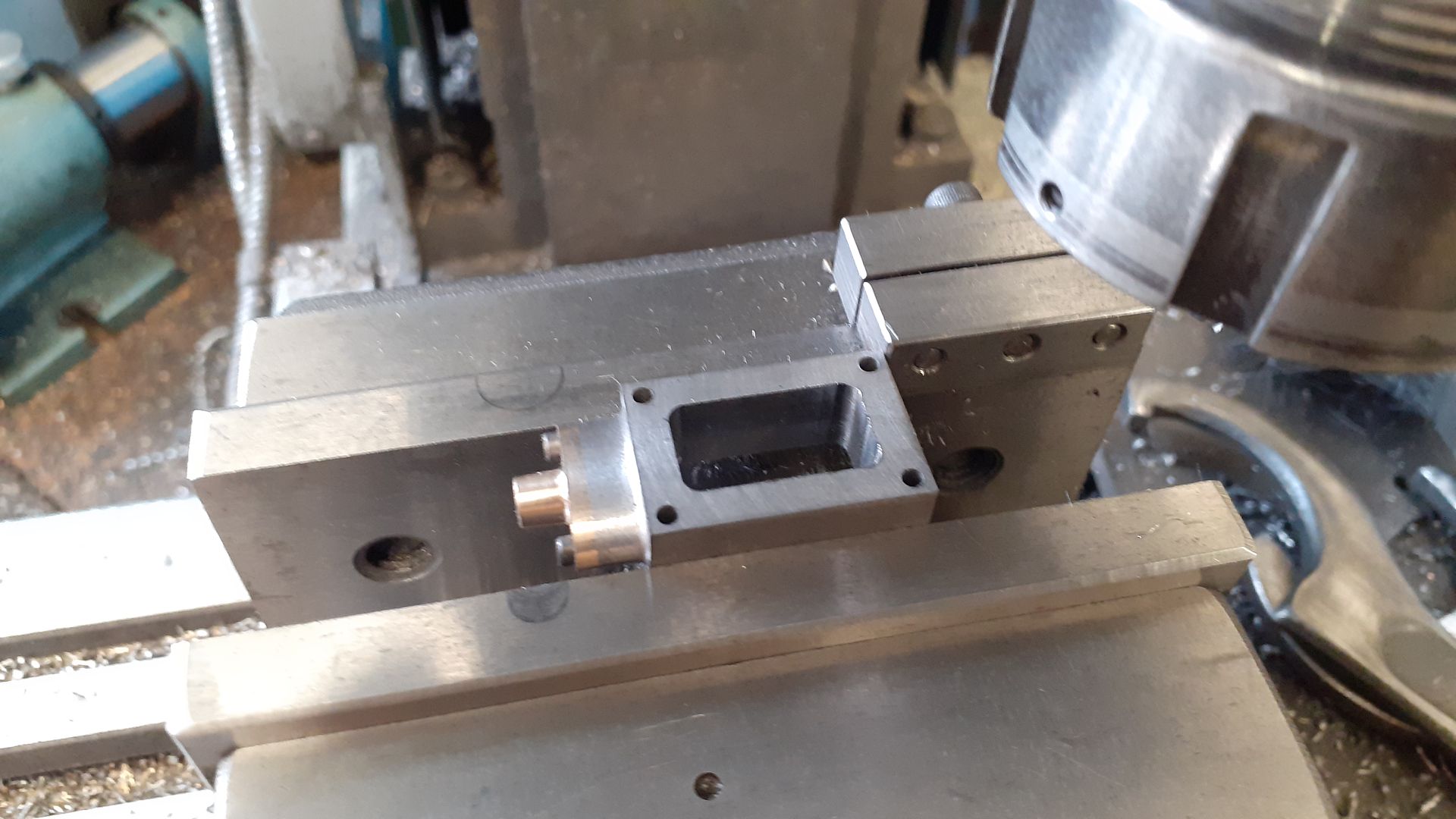
When I originally started to draw this up I had intended to build up the main bed "casting" from some 2" x 1" aluminium flat bar adding the bearing and guide rail bosses to the top as well as the cylinder support as a separate piece. However as I got closer to making a start I had second thoughts and decided that the bed would make an interesting part to cut from almost one solid block. looking around at prices it was more economical to start with 40 x 60 flat EN3 steel than 2" imperial steel or aluminium stock so a length was ordered from M-Machine and duly milled down to the required 34mm finished height with the length and width plus 2mm to give a 1mm all round machining allowance for the. While it was an easy to hold rectangular block I milled and tapped 3 pockets for the feet which will be done as separate parts to reduce the waste material. I also tapped tow M8 holes so that I could mount the stock to a block that could inturn be held in the machine vice

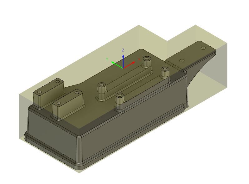
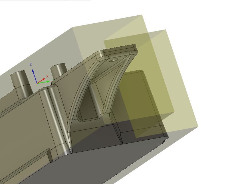
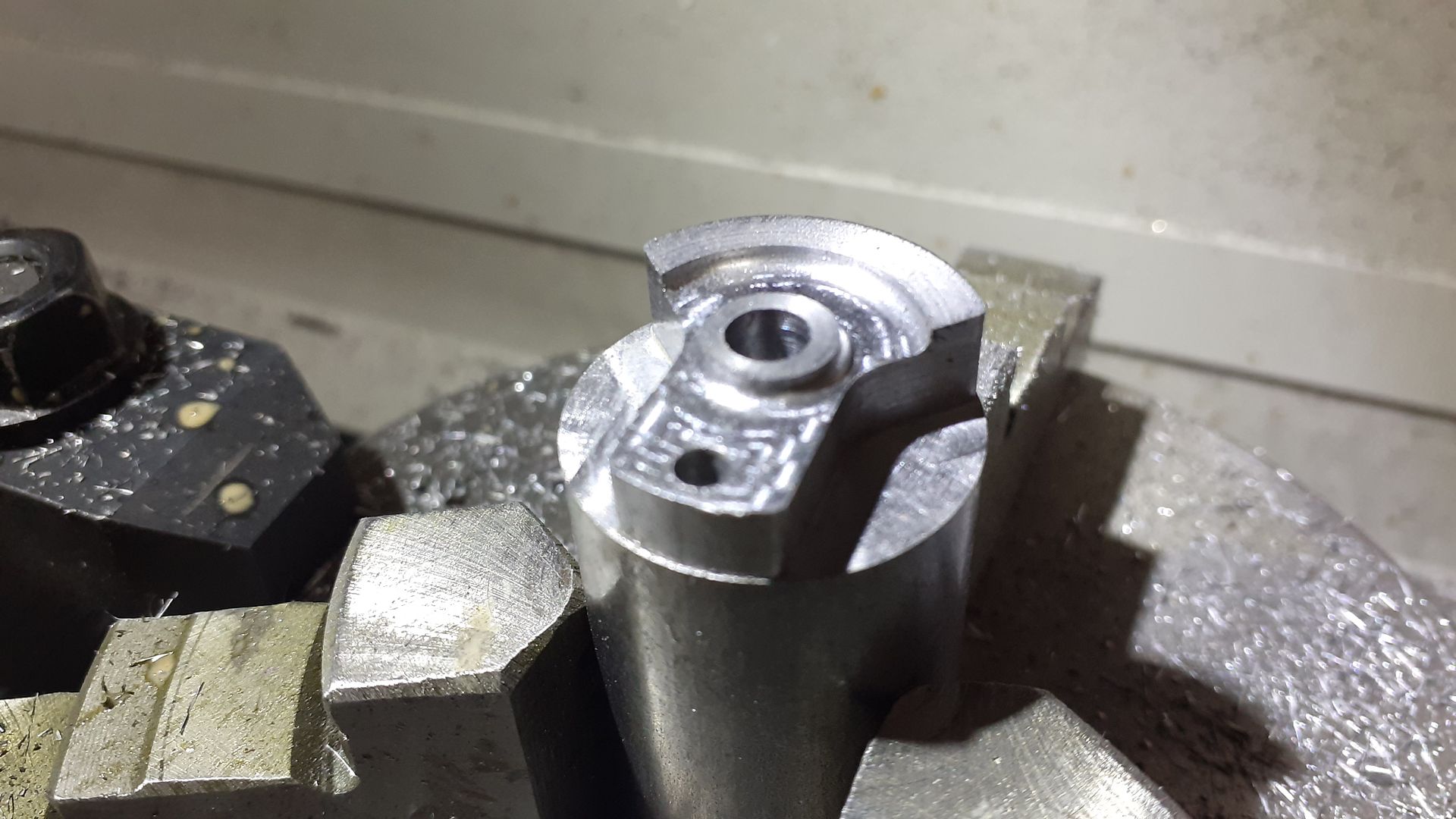
To reduce the amount of CNC time I sawed out one corner of the block and modelled that in F360 to use as my setup stock, her you can see the part lurking within the "L" shaped stock

A second setup was required to machine out the material under the cylinder support

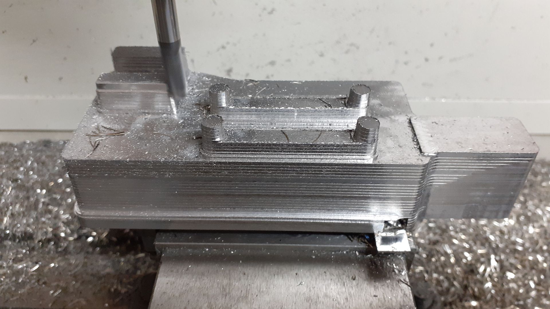
This shot shows the results of an adaptive clearing tool path that leaves a series of steps on the sloping surfaces as they all have a draft angle to mimic the casting and one of the finishing paths has just started to work it's way down around the near bearing block boss.

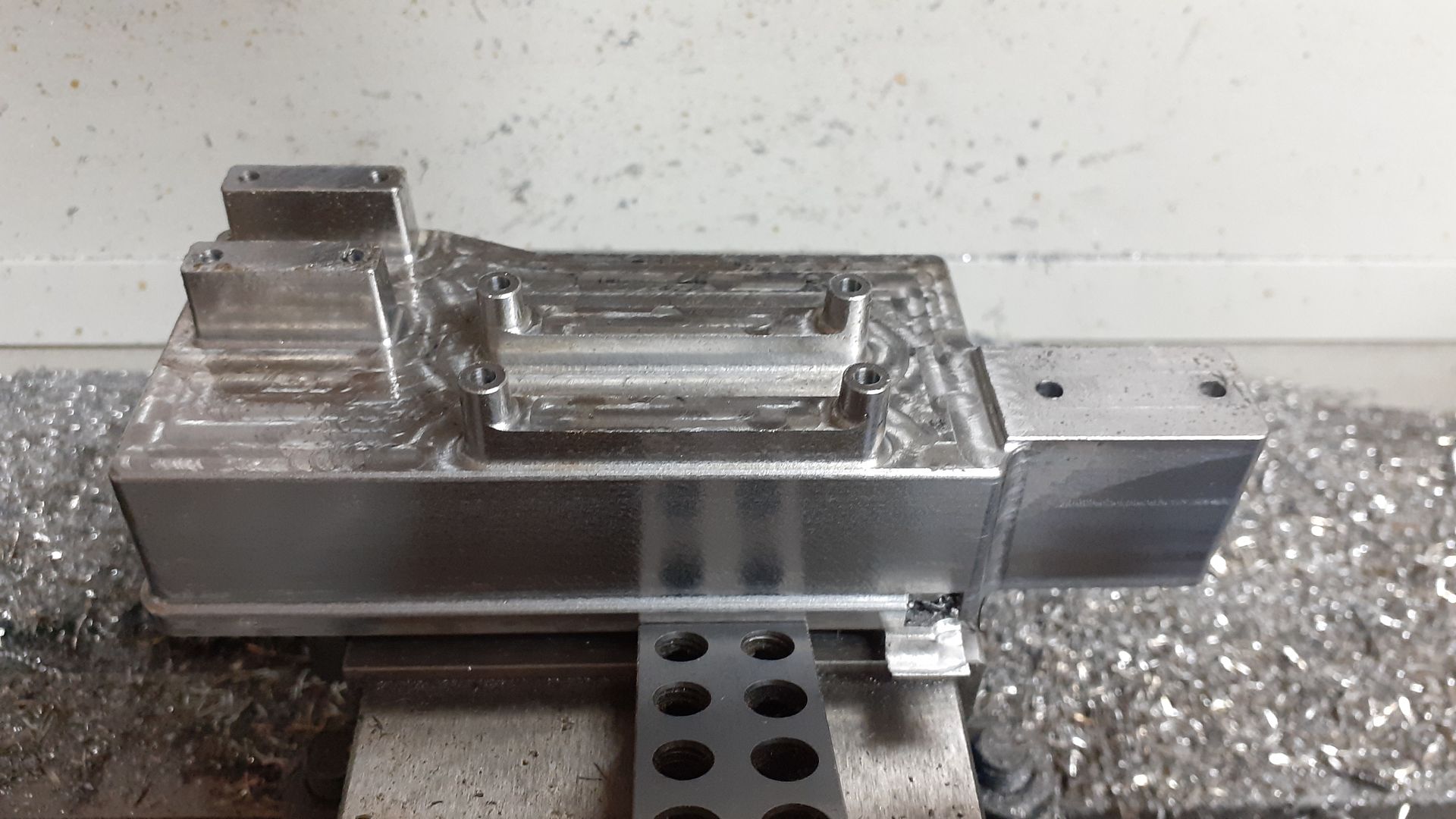
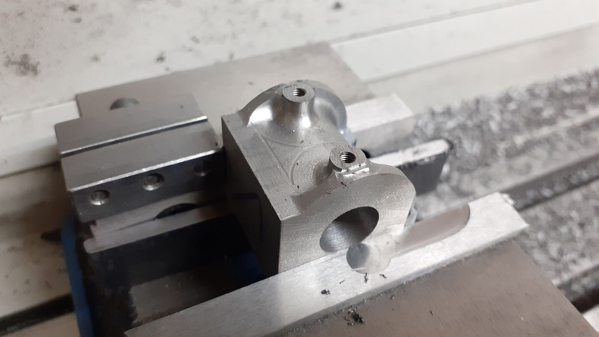
And once all the finish paths have been completed. I also drilled all the holes at this setup with the CNC but manually tapped them although I did reposition the spindle above each hole to help guide the tap vertically

From a slightly different angle the light falling on the more matt near vertical faces shows where the draft angle feathers out under the cylinder support the brighter material which is the vertical "shadow" below will be removed with the second setup

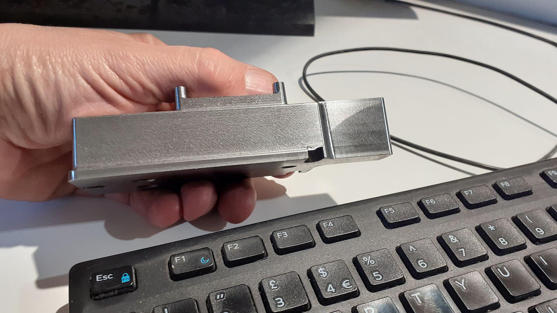
I did muck up my edge finding for the second op but was able to recover things by using some U-pol Rapid filler and running the cut again in the correct position, you can just see the lighter coloured filler on the right hand inner face of the support webs.

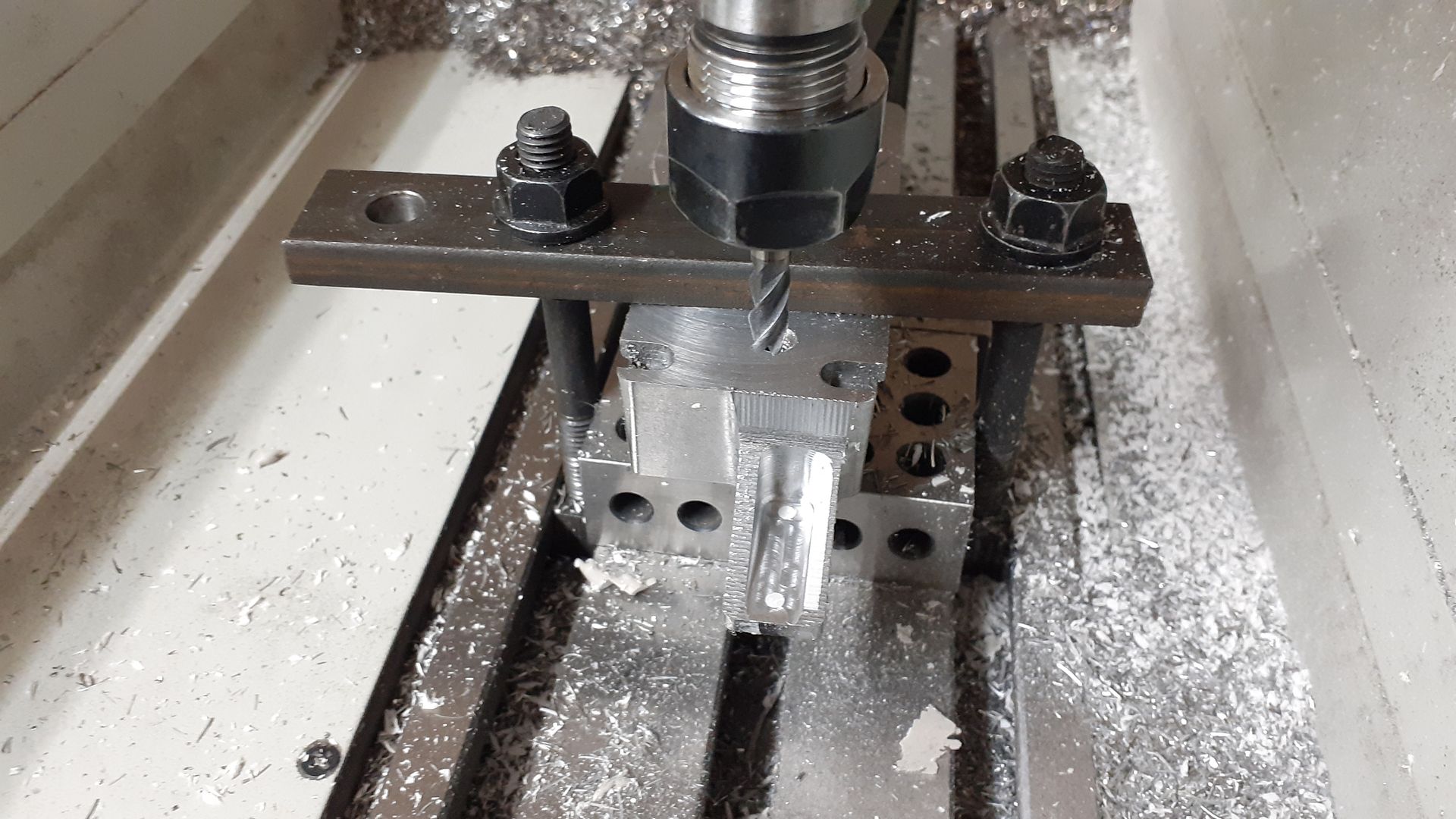
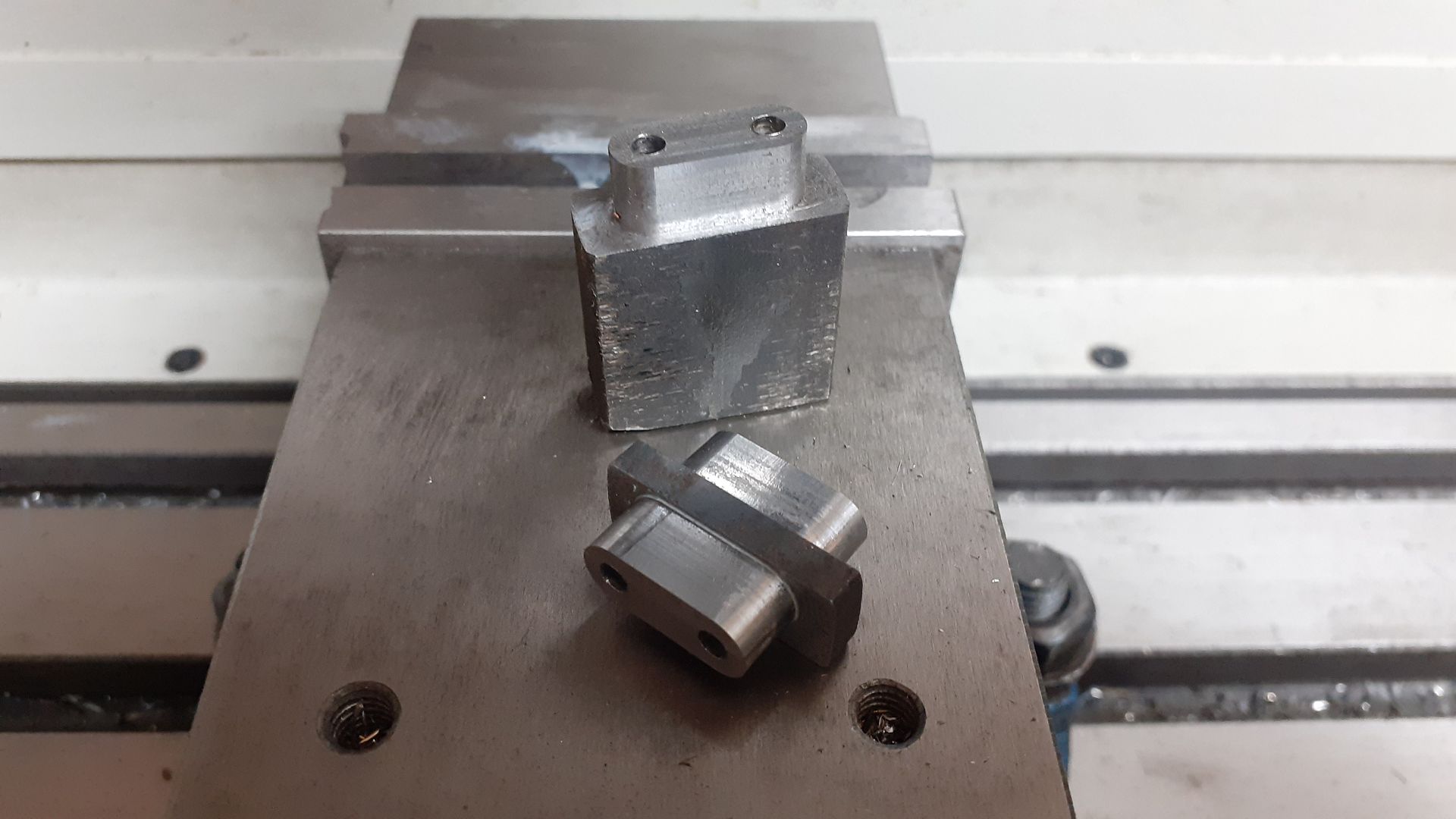
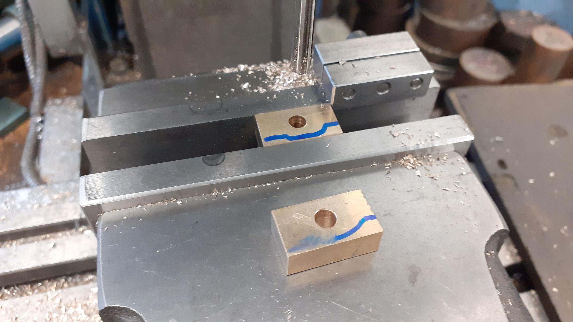
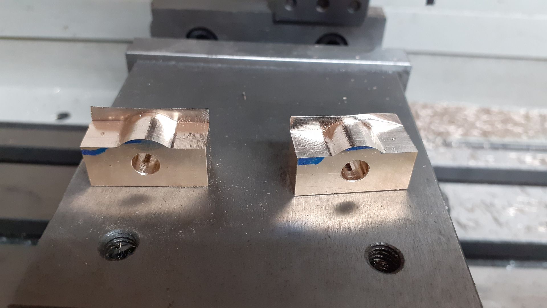
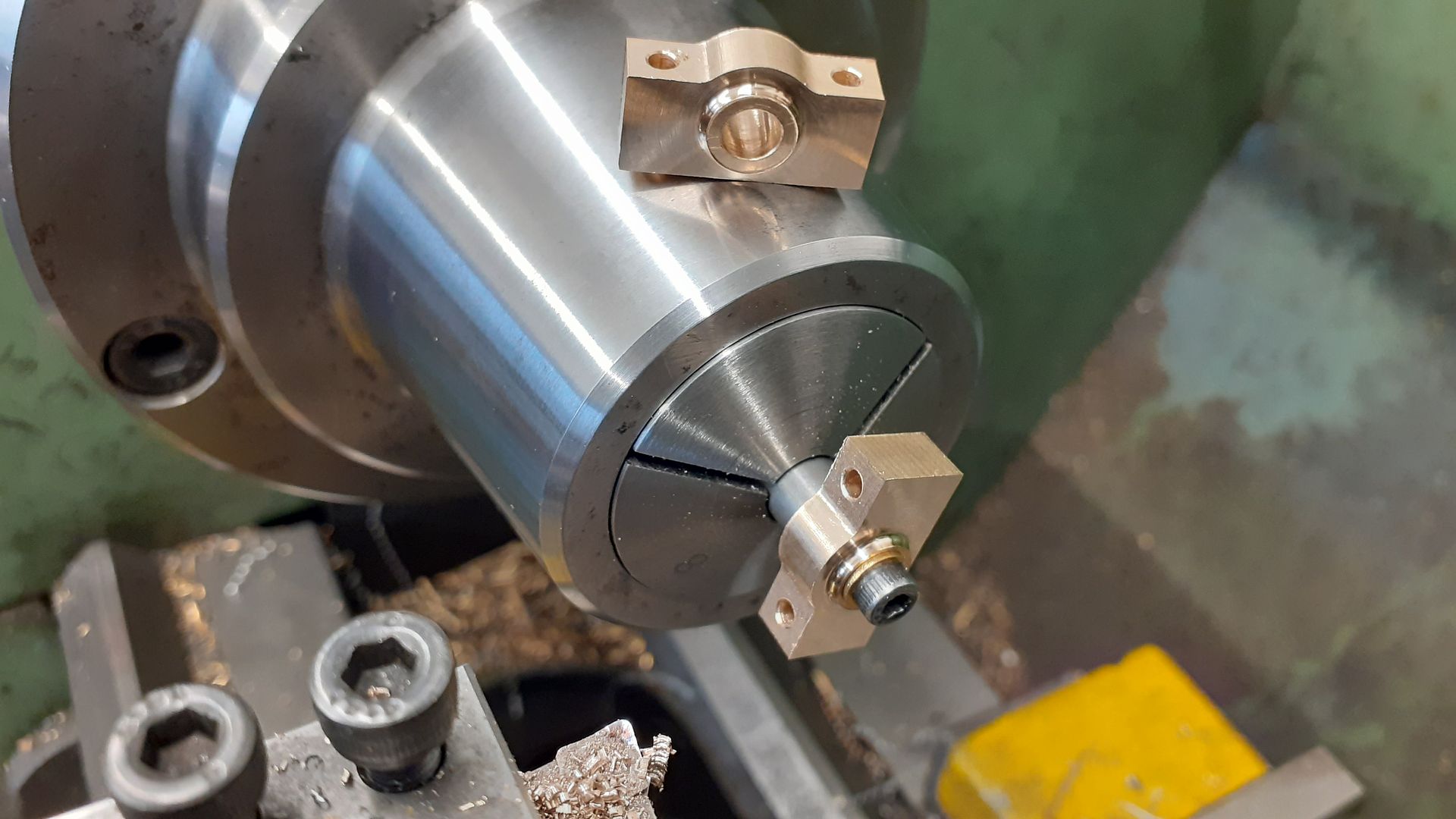
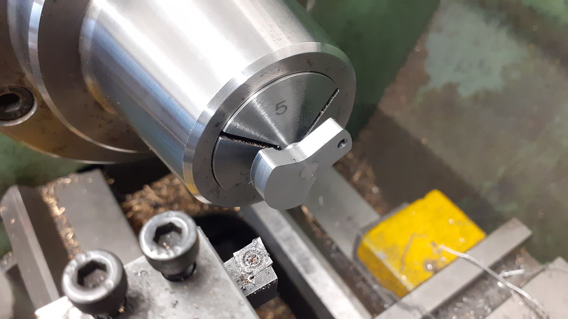
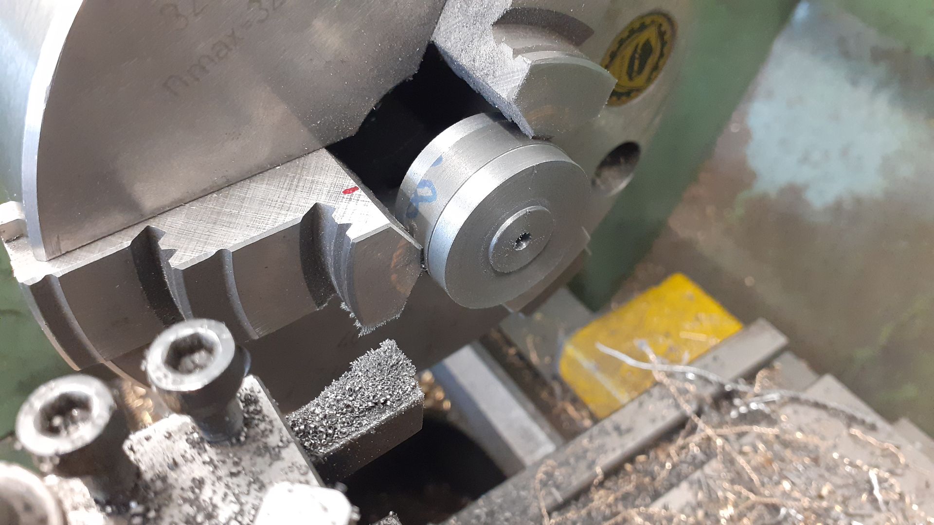
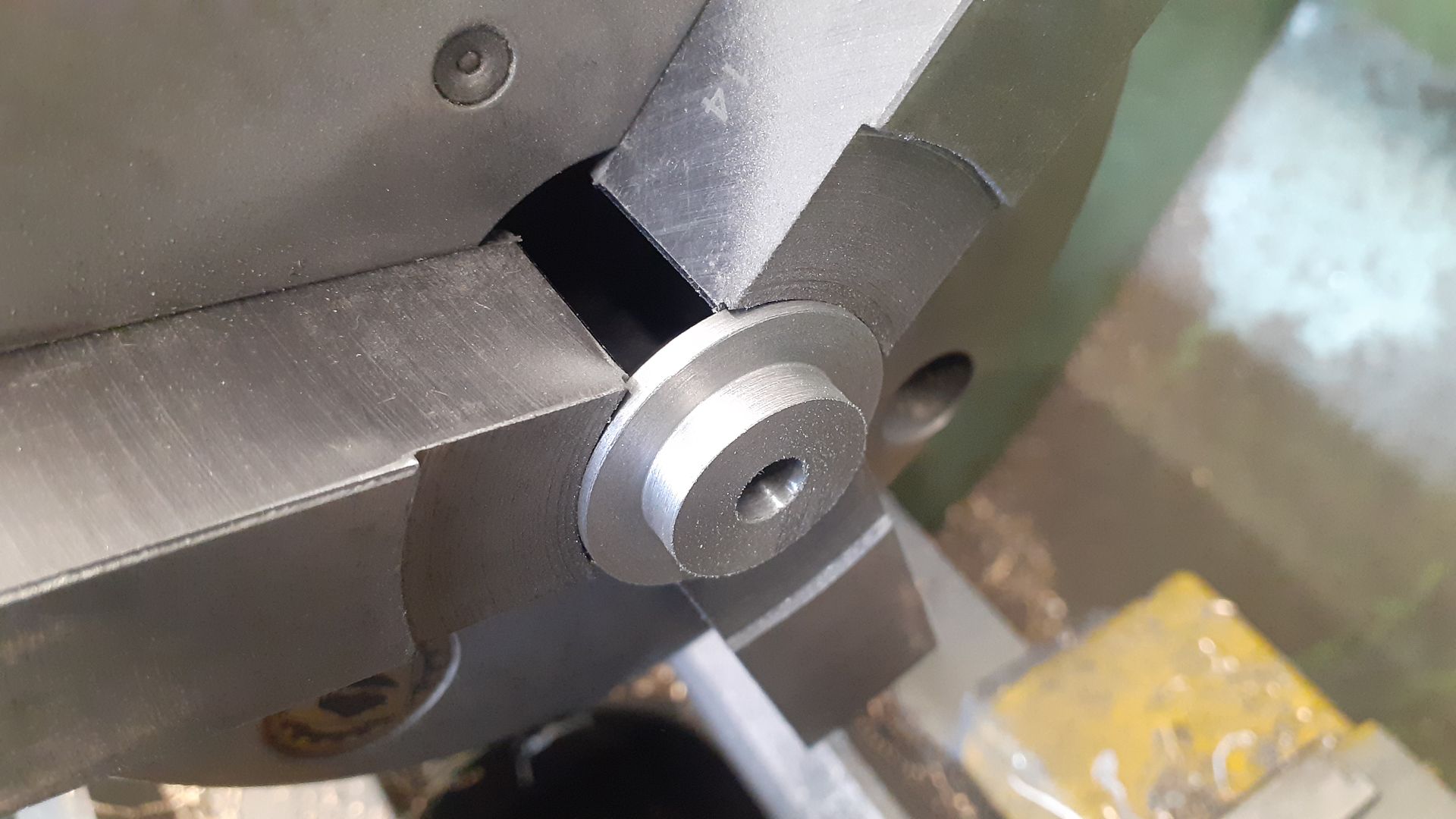
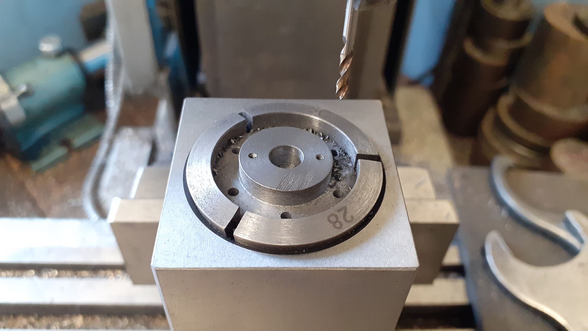
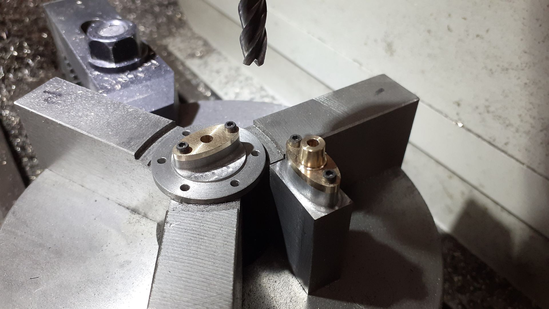
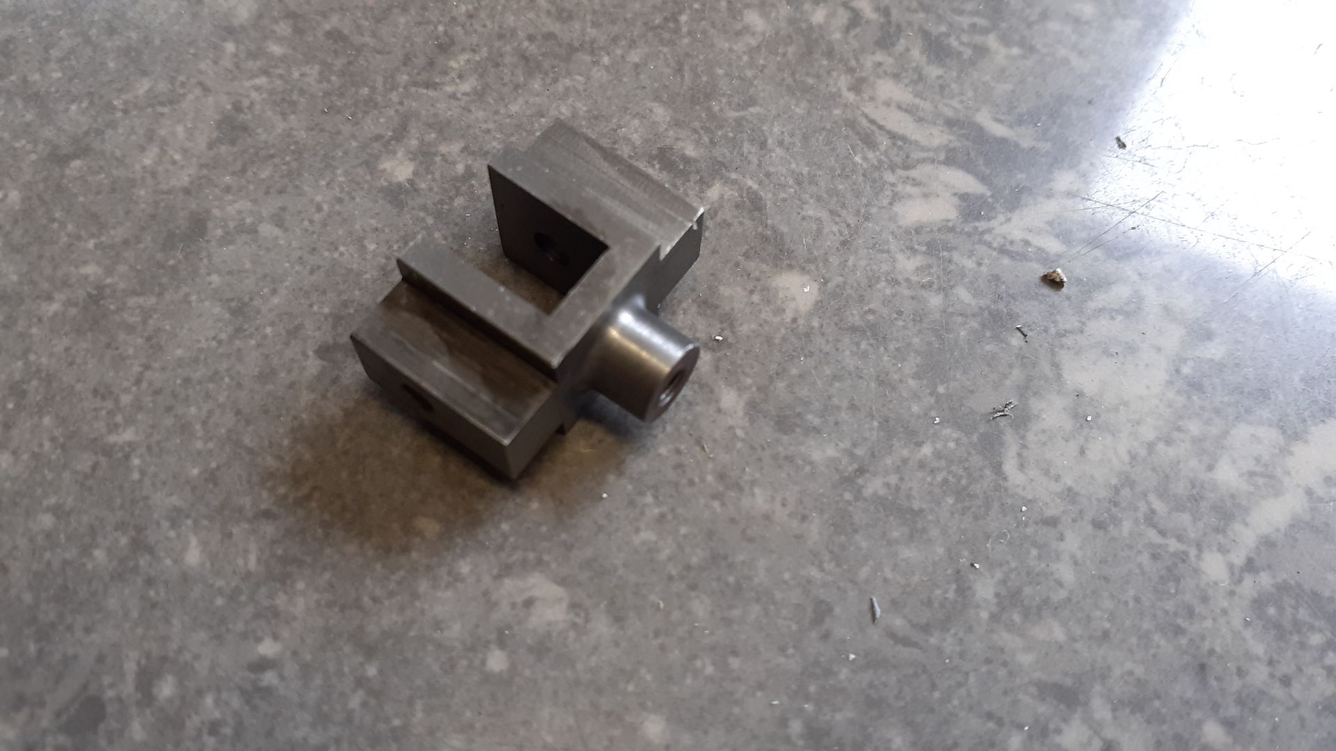
While the CNC was warm I also did the three feet on that doing both the milled profile and the two holes, these were then sawn off the scraps of bar, machined to 4mm thick and then screwed and JBWelded into the pockets on the underside of the bed.

Tim Stevens.


