Part 8
Many simple parts can be 3D modelled with only the Pad, Pocket and Revolve tools. For that reason it’s worth practising with them several times. Early on keep it simple, pick simple shapes, and don’t be discouraged when you hit brick-walls. They may be because imagination has failed, more likely another modelling tools is needed. Understanding which CAD tool to use is part of the learning process, akin to knowing when to use drills, 2-flute cutters, 4-flute cutters, or fly-cutters in a milling machine.
As the world is complicated, so are the 3D tools needed to model real-world objects. Faced with a new 3D-CAD package, the sheer number of options available is intimidating. Don’t panic: it might take time to crack the code, but the more you explore the easier it gets. You don’t need to learn everything; chances are hobby metal workers are making relatively straightforward shapes, not designing the sweeping plastic curves added to beautify vacuum cleaners!
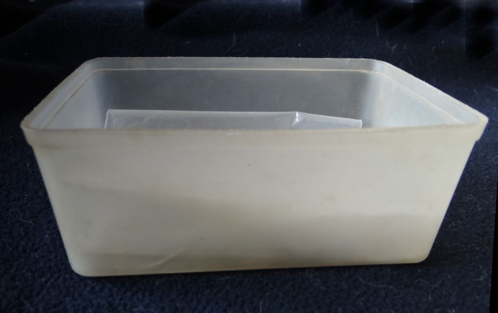
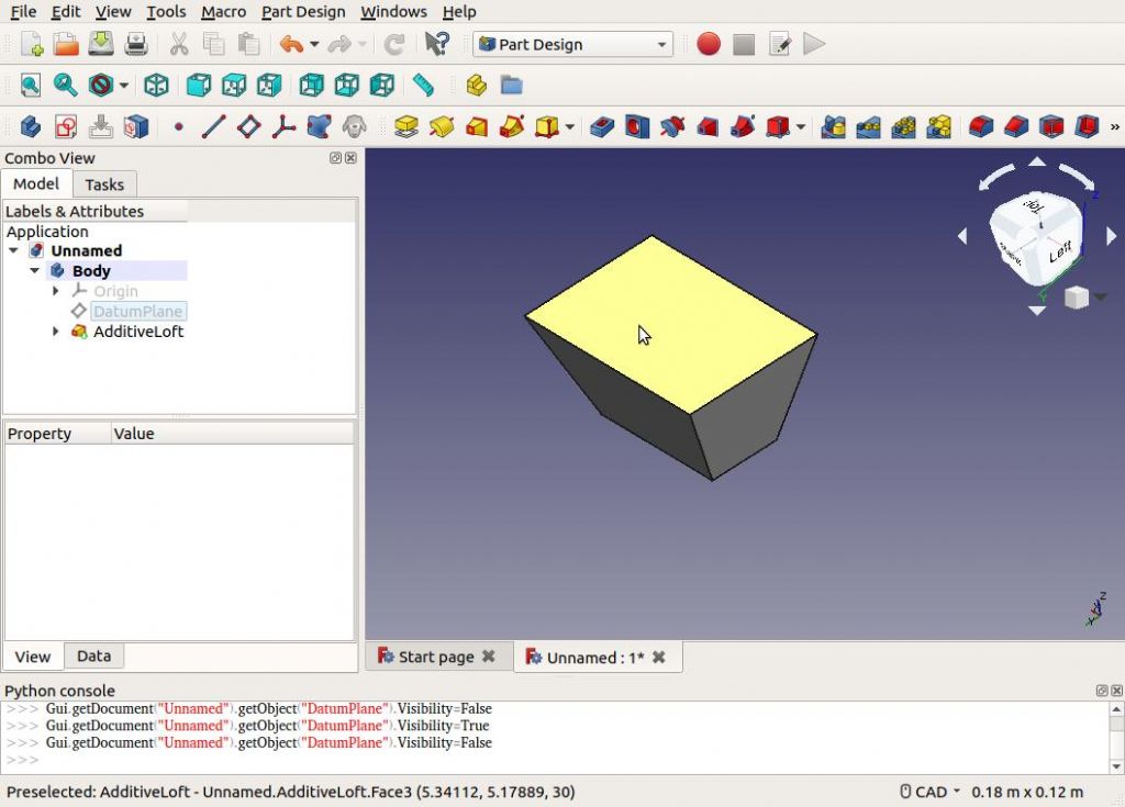
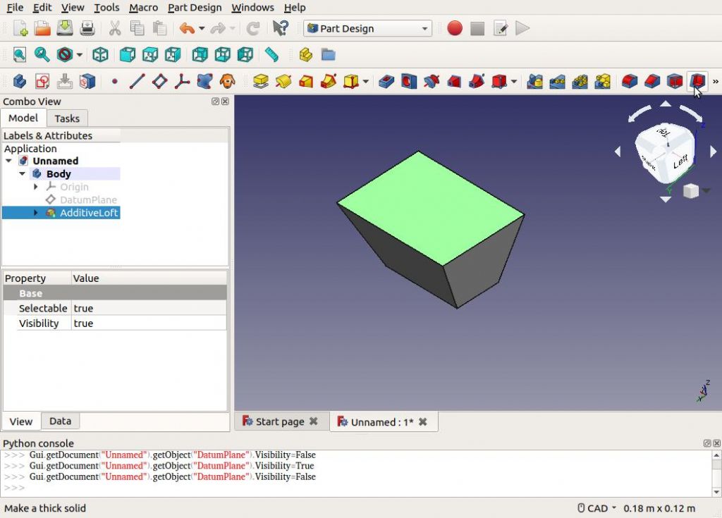
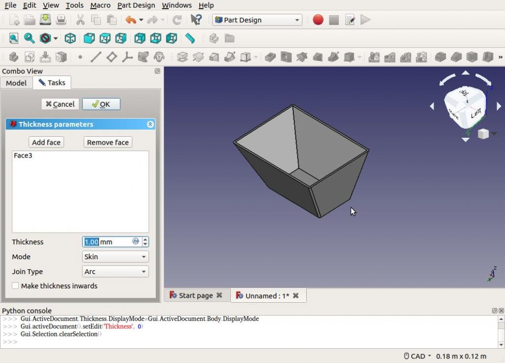
This example shape is used for everything from ice-cream containers to wheelie bins. It needs a new tool.

‘Lofting’ is the CAD process of generating shapes in the gap between two sketches. Be warned, loft is somewhat fiddly in FreeCAD. If something doesn’t work, go back and try again. One cause of bother is that given a few possibilities, the software may not select what the user intended. Sometimes helps to rotate, zoom-in or hide features to make sure the correct object, face or edge is selected.
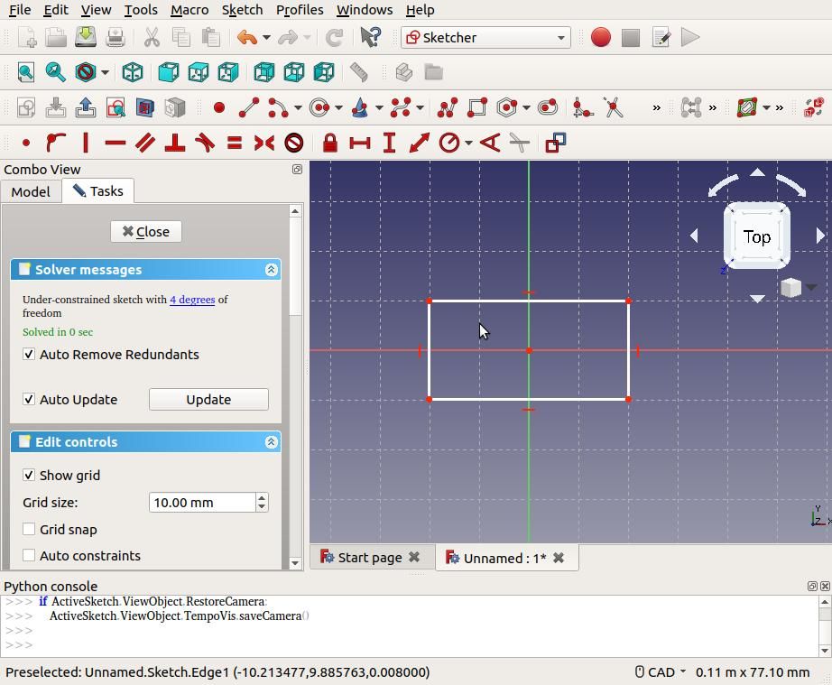
First open the sketcher and draw a rectangle representing the container’s base. (In the example I’m not bothering to constrain the sketch as would be necessary to model a real container.)

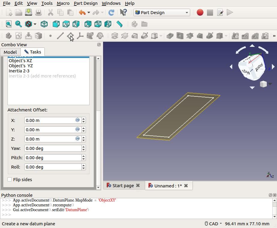
Close the sketch and click the ‘Create a New Datum Plane’ button.

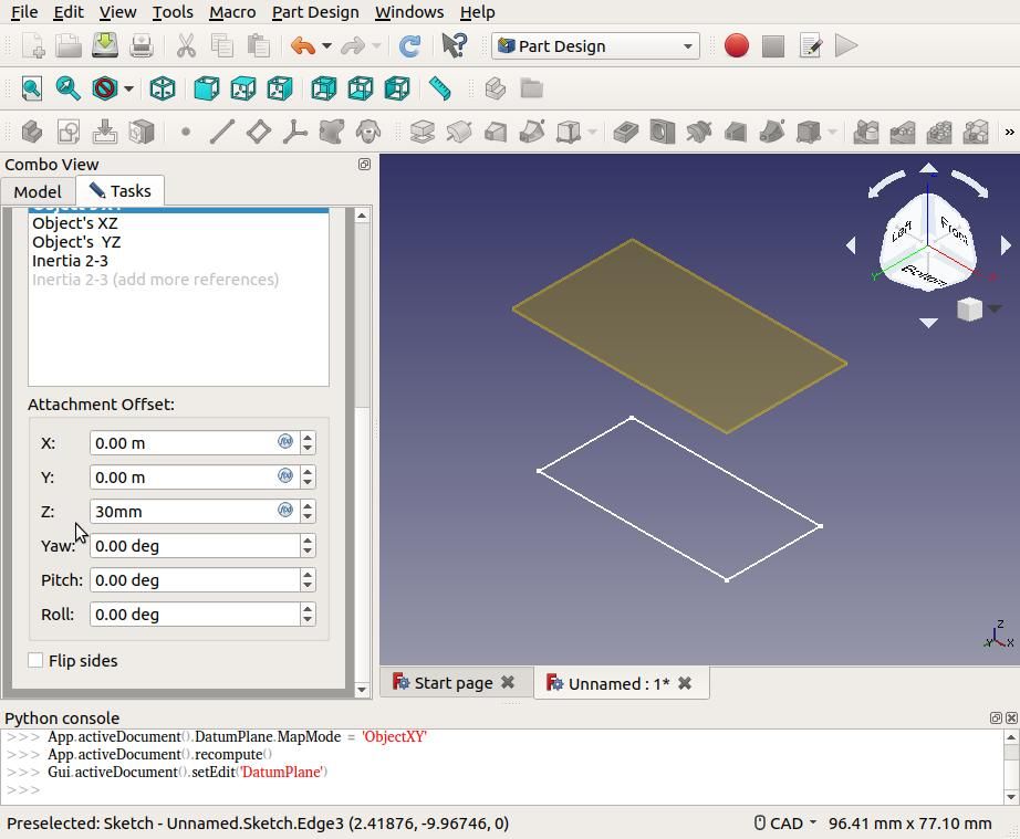
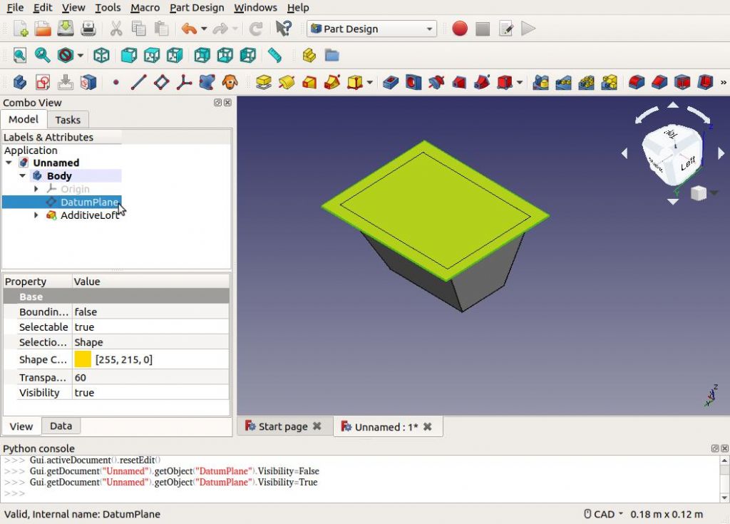
Now lift the new plane 30mm above the existing sketch by typing 30mm into the Z Attachment Offset. (Watch out! Offsets default to metres. If annoying, before starting a new project have a look at Edit→Preferences→Units. Default setting is MKS: you might well prefer ‘Imperial Decimal’ or ‘Metric Small Parts & CNC’, aka mm)

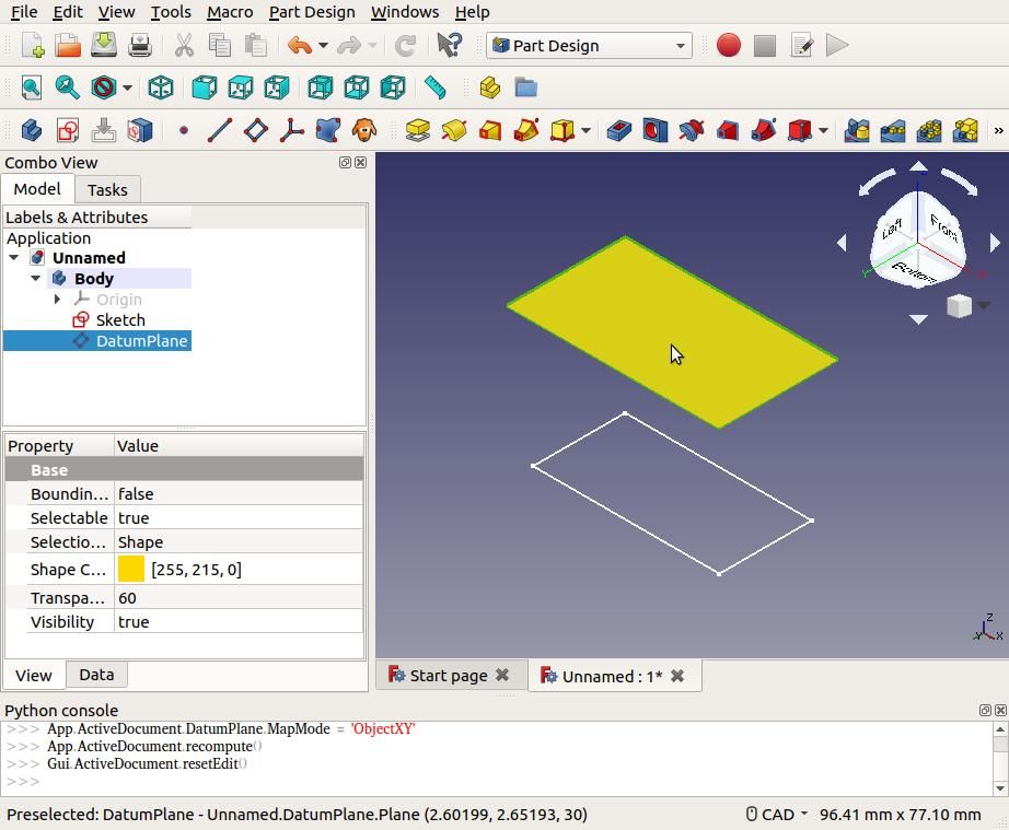
Close the Datum tool by clicking on the OK button at the top, then click on the new datum plane to select it.

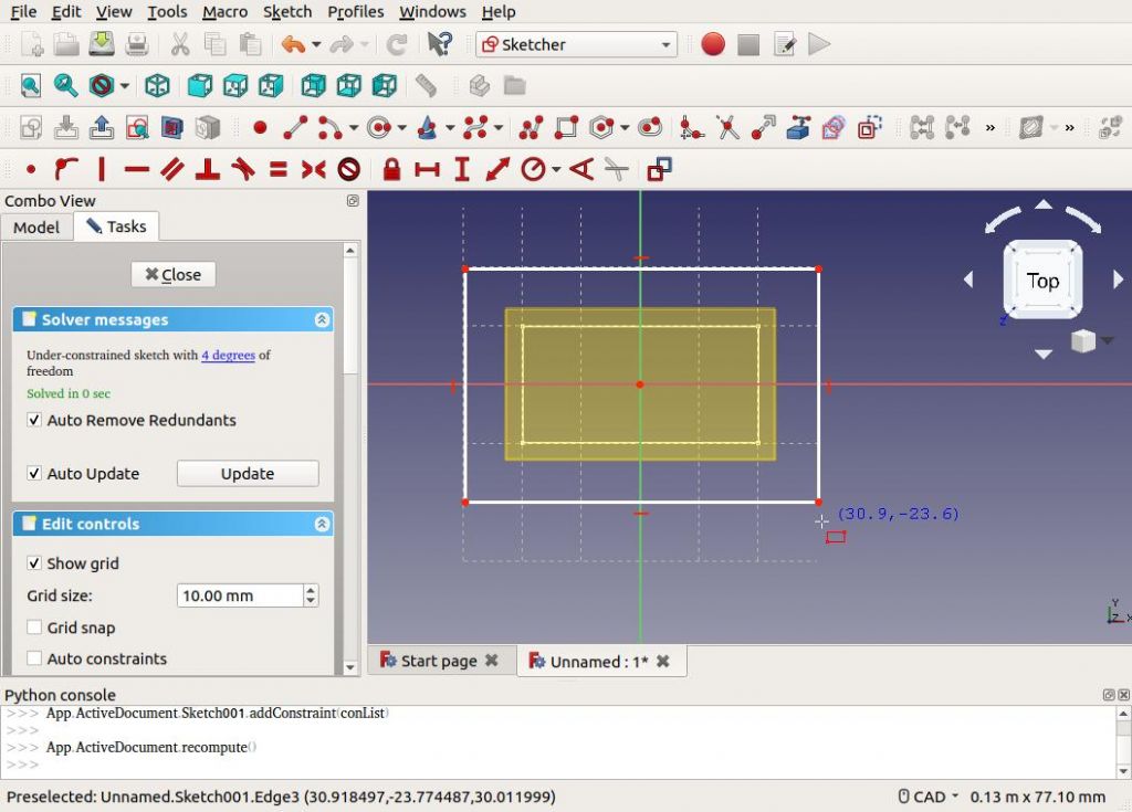
Create a sketch on the new plane. The earlier sketch can be seen underneath. Draw a larger rectangle to represent the top of the container.

Close the sketch, revealing the model now has two sketches.

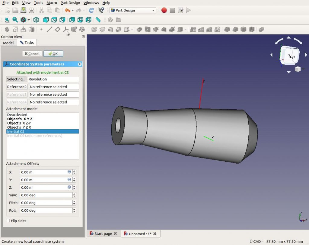
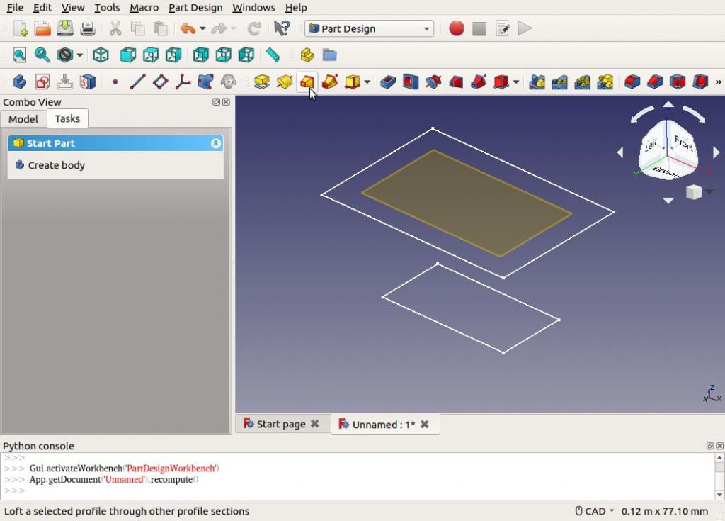
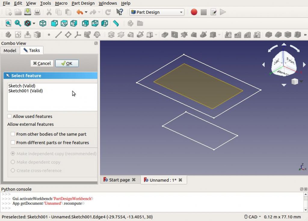
Click on the ‘Loft a selected profile through other profile sections’ button. Select one of the two sketches. I chose the base.

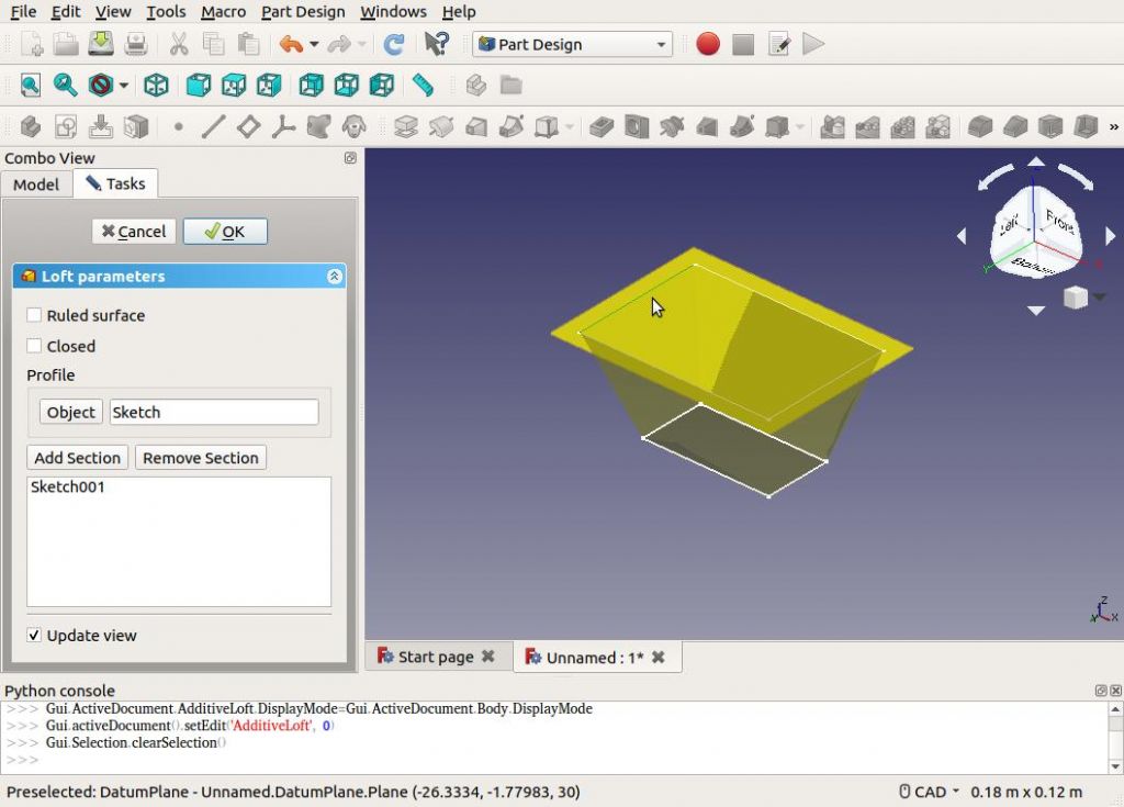
The next dialog requires a ‘Section’ to be added. In this example, it is any of the top four edges of the container. Clicking one edge highlights the loft. (Note a loft can follow more than one sketch at different levels, each defining a section of a complex shape.)

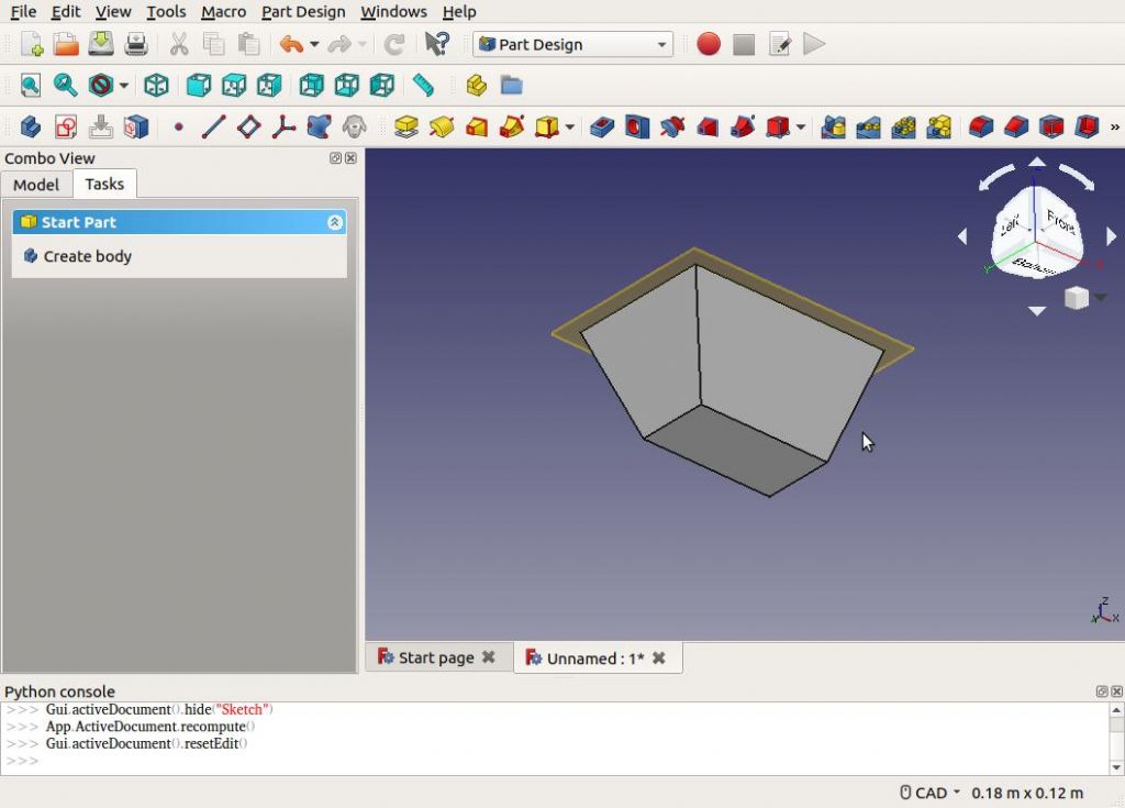
Clicking the OK button generates the solid.

More…
Ronald Morrison.


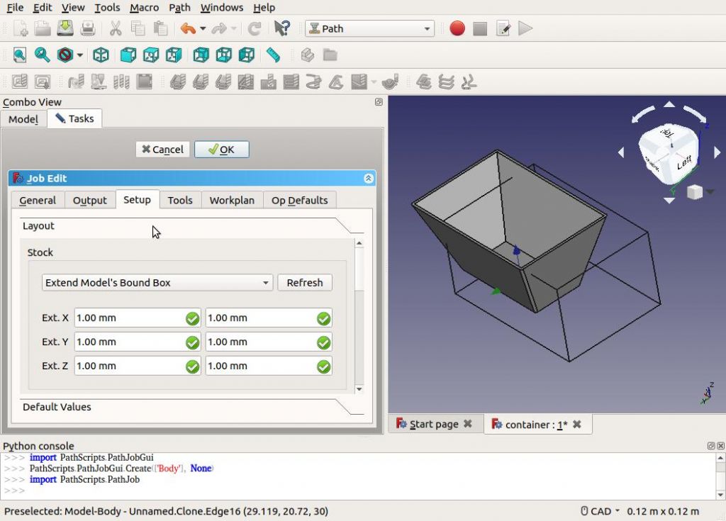
 to external edges only. Anyone any ideas – without getting deep into python?