Part 2
3D CAD eliminates many 2D drawing errors, and, once mastered, the process is generally quicker. It works by developing solid models, not views. Although ‘Sketching’ is part of the process, it might help beginners to dump the idea that 3D CAD is drawing at all. Think ‘modelling’ instead of drawing, albeit the solid model only exists inside a computer. Seeing the model on-screen in 3D makes it much easier to spot mistakes.
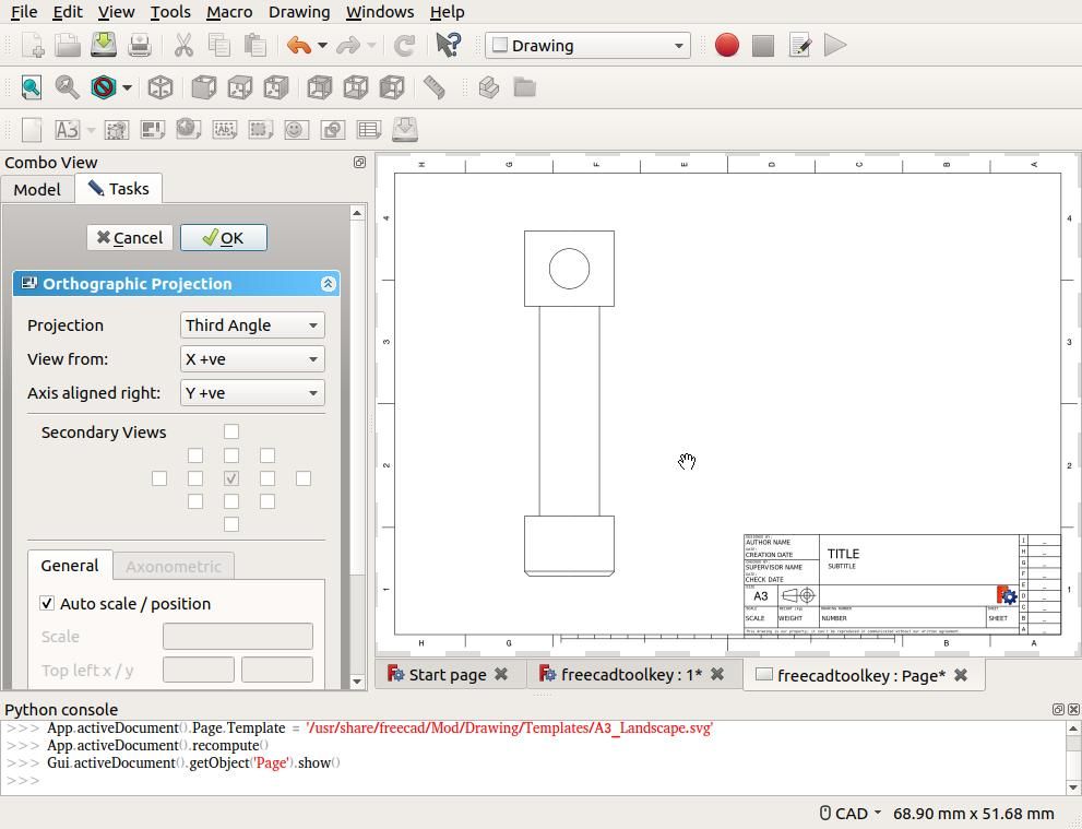
3D CAD offers various ways of converting the model into a real object. For a manual workshop, the 3D model can be rendered as 2D drawings in First or Third Angle. Another output is photo-realistic views of the object, in metal, with or without paint. Yet another representation is a mesh for stress/strain analysis. Another common output is the G-code instructions needed to create the real object with a 3D printer, usually plastic but concrete and metal are also possible. Or the G-code needed to make the object by cutting in a lathe or milling machine. Stamping, grinding, engraving, laser cutting, etching and other manufacturing processes might be available too.
Many human errors are eliminated because the outputs are produced automatically direct from the solid model. In the event the model is changed, it often unnecessary to rework the outputs; asking a computer to generate a complete set of new 2D drawings is much easier than asking Mr Grumpy to start again!
Sadly, these advantages aren’t handed to the user on a plate. The software looks and can be intimidating. As always, best to start simple and work up. Like riding a bicycle, with luck CAD will suddenly make sense.
Here’s the plan:
-
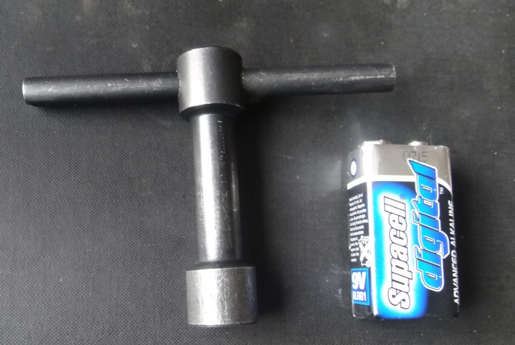
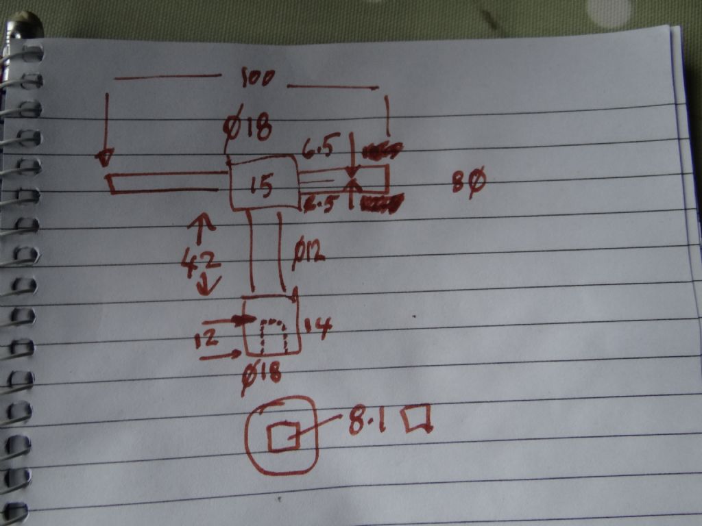
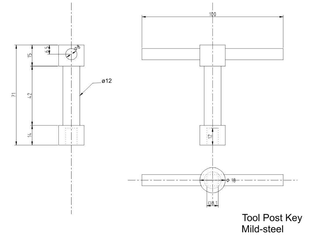
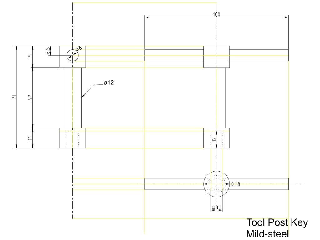
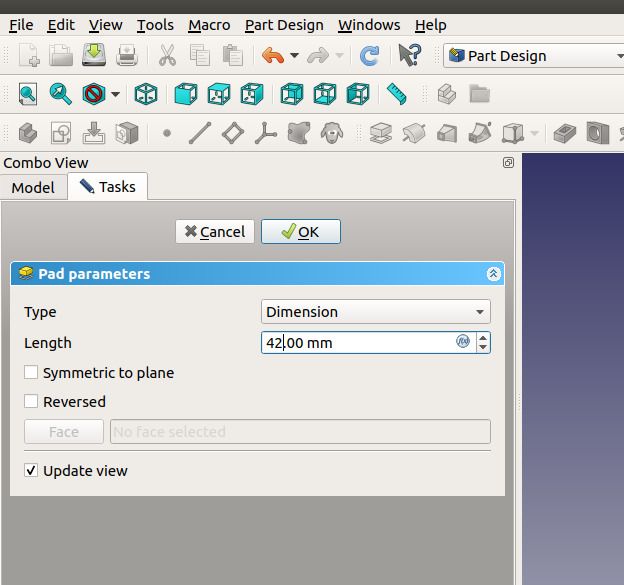
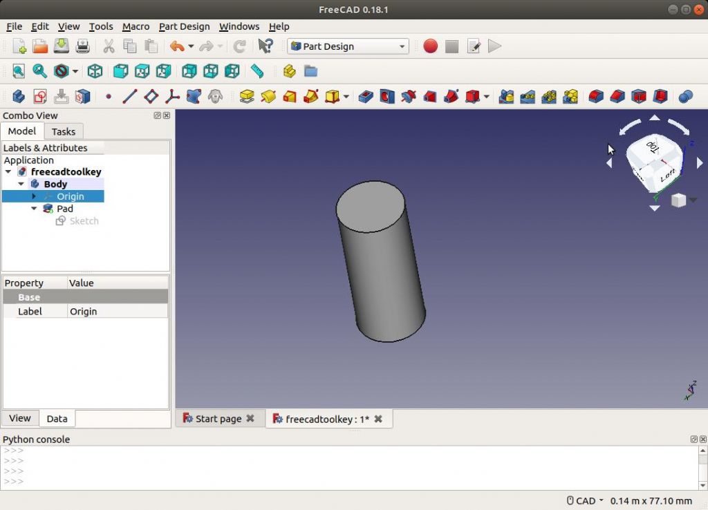
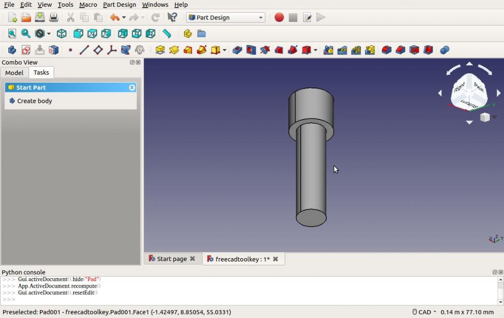
Create the 42mm x dia 12mm centre shank
-
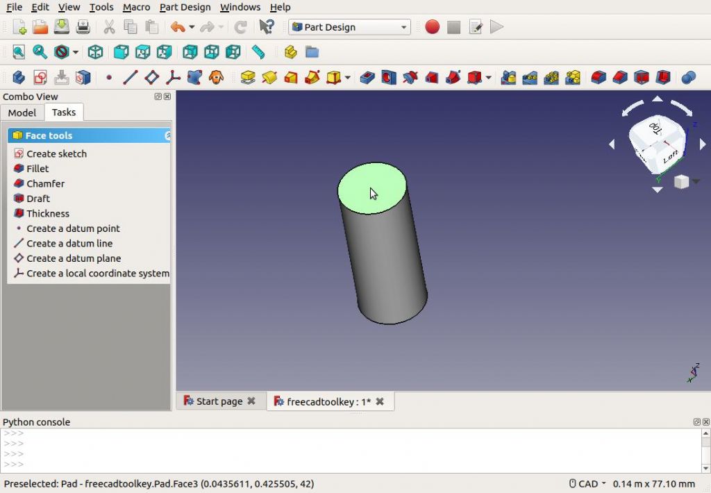
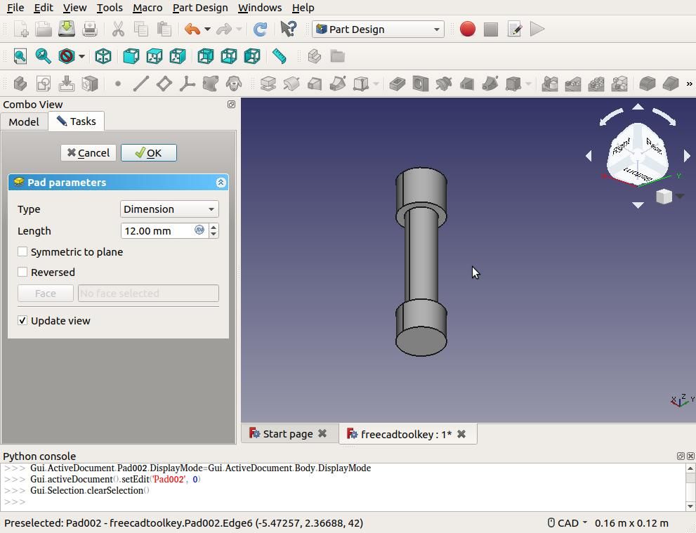
Add the 15mm x dia 18mm top
-
Add the 12mm x dia 18mm base
-
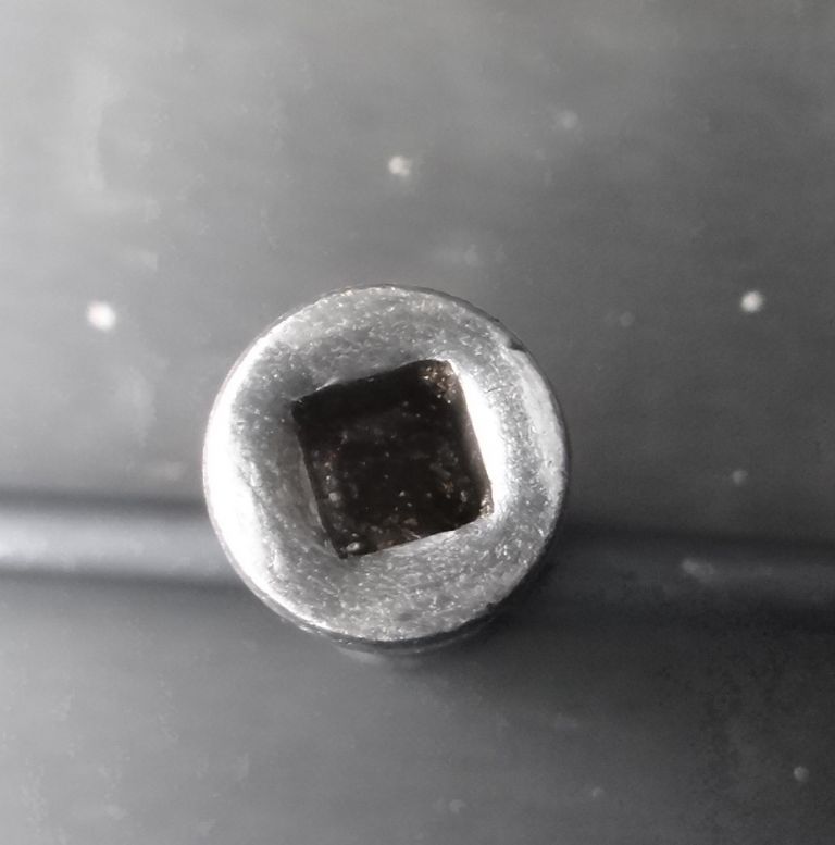
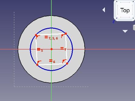
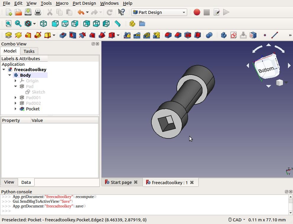
Cut a 8.1mm square hole in the base
-
Add the handle
-
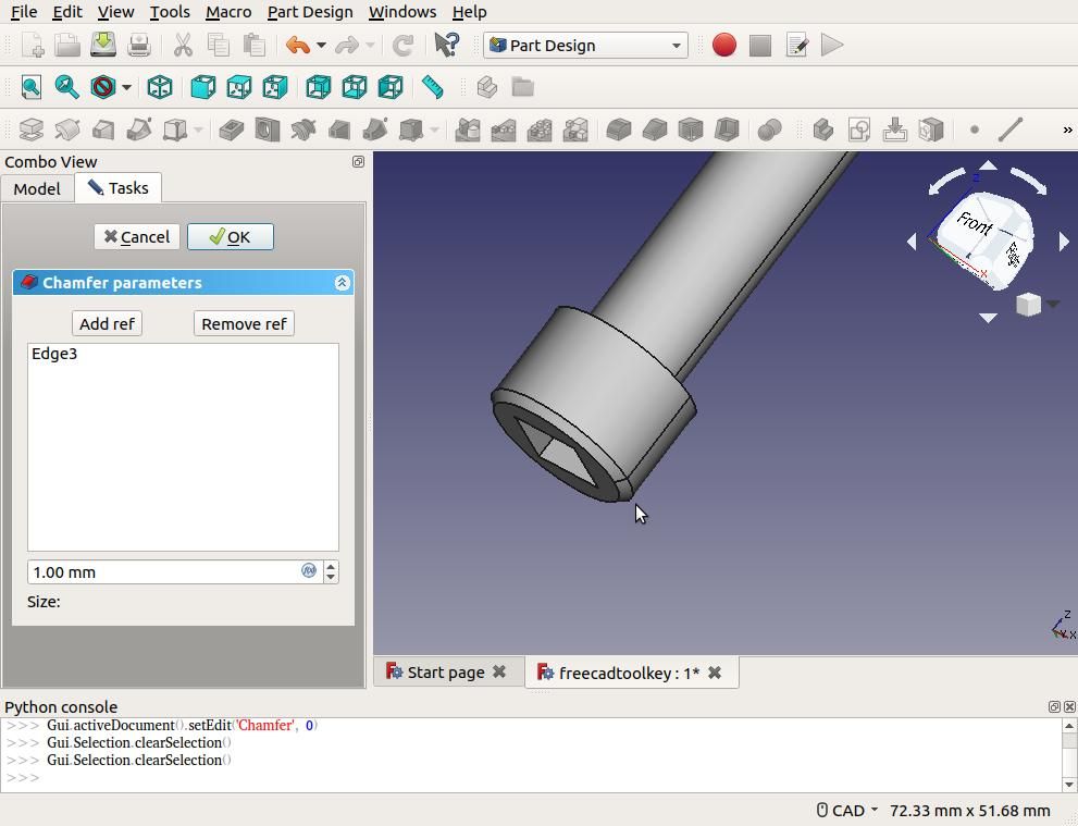
Beautify with Chamfers
-
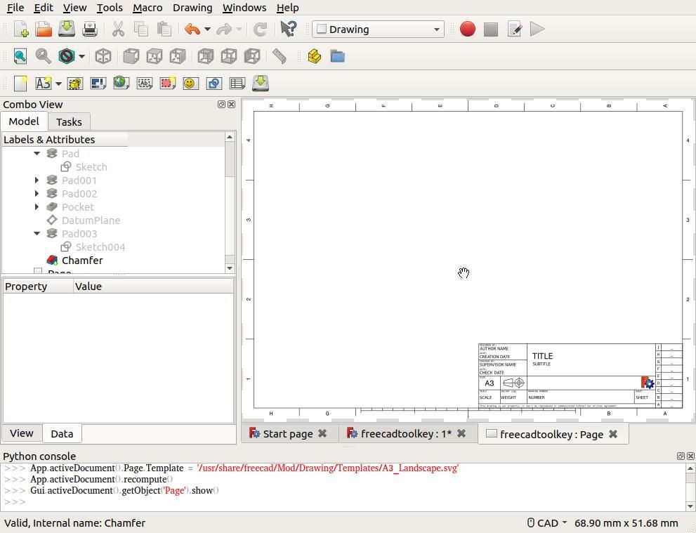
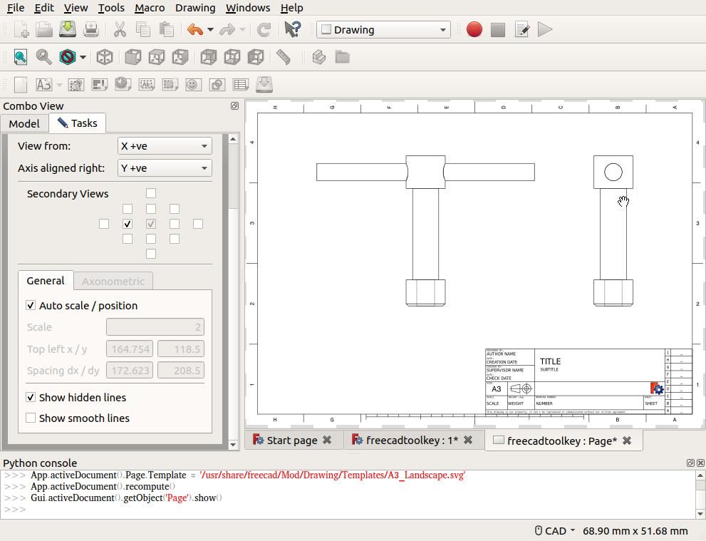
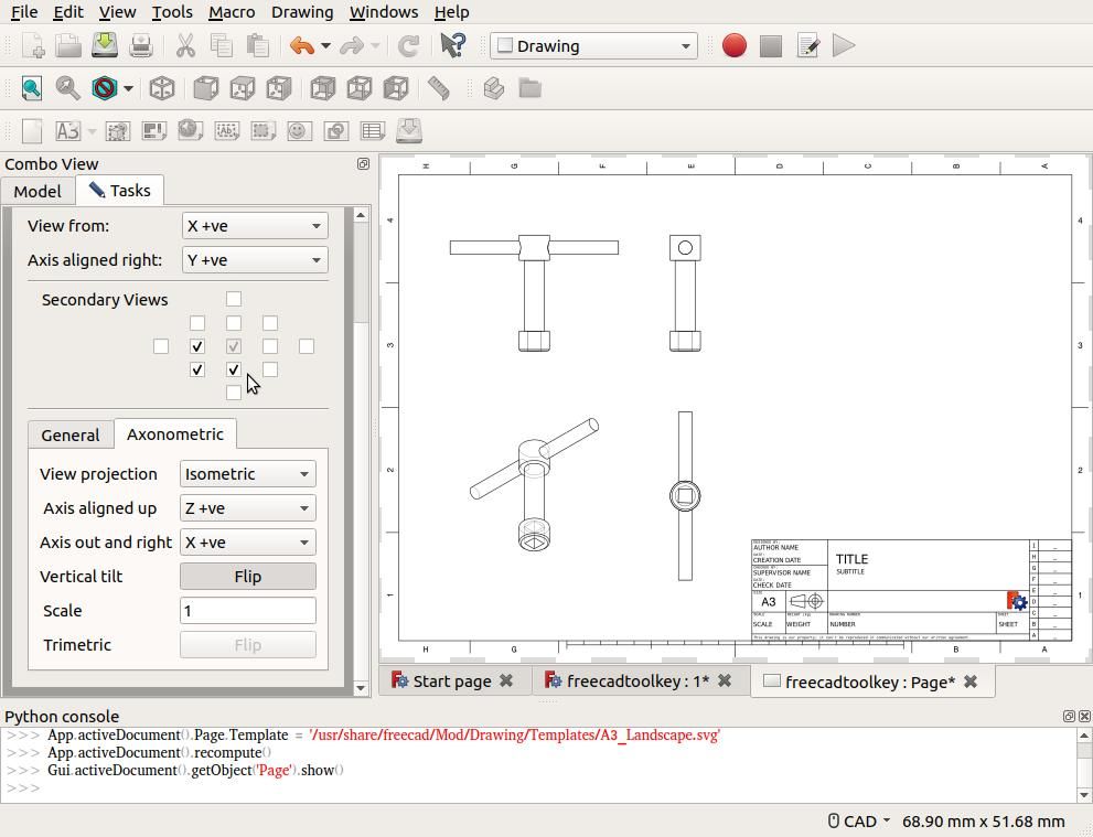
Generate 2D Drawings.
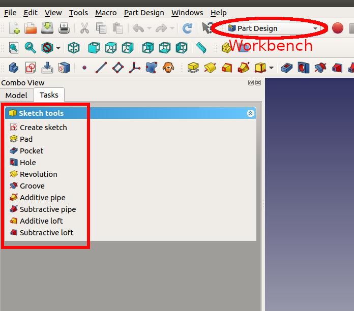
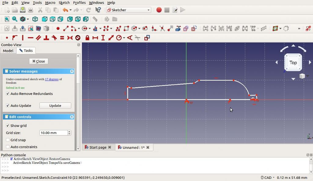
Start FreeCAD, and follow the earlier instructions to get into the Sketch Editor in the Part Design Workbench. Note that Sketcher Buttons marked with red-dots and white lines are drawing tools, (lines, rectangles & circles etc), while those all in red force constraints, parallel, vertical, distance, diameter, angles tangents etc. Hovering over the buttons should display what they are. Useful tips:
-
the ESC key ends the current action.
-
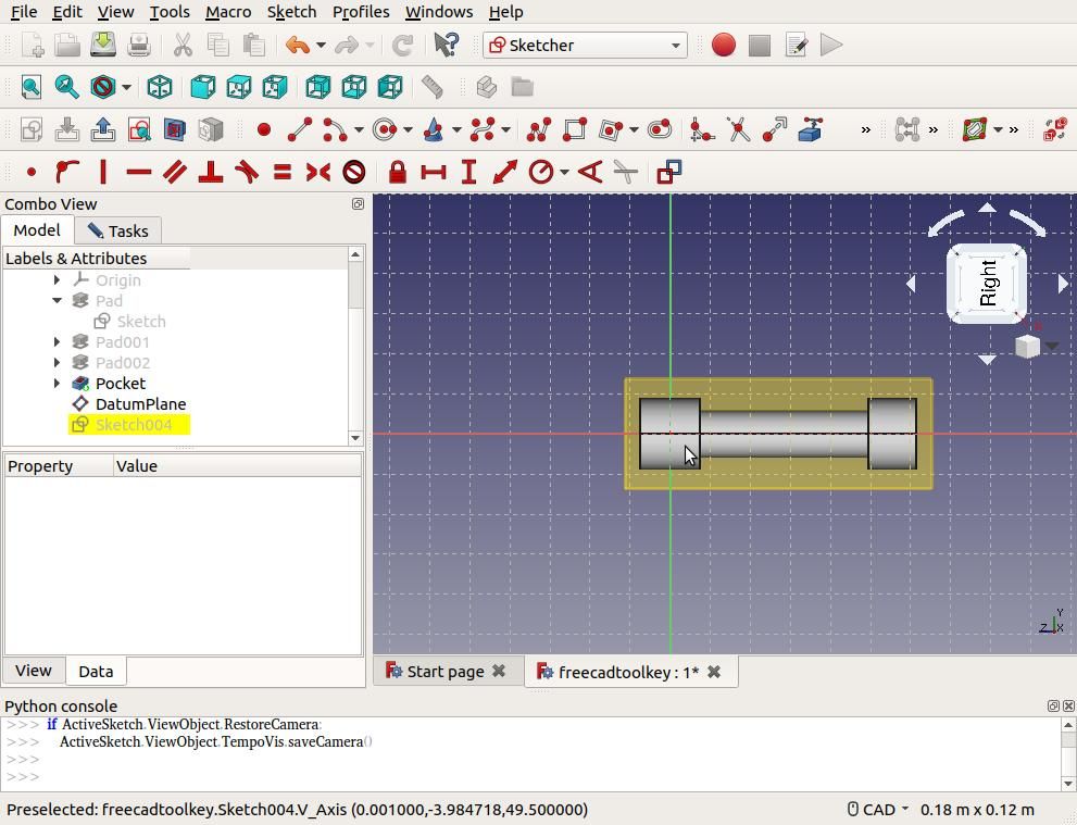
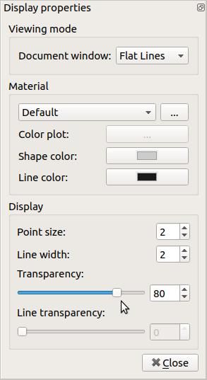
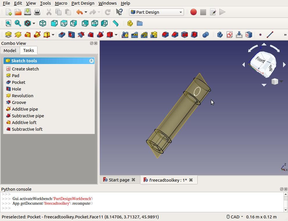
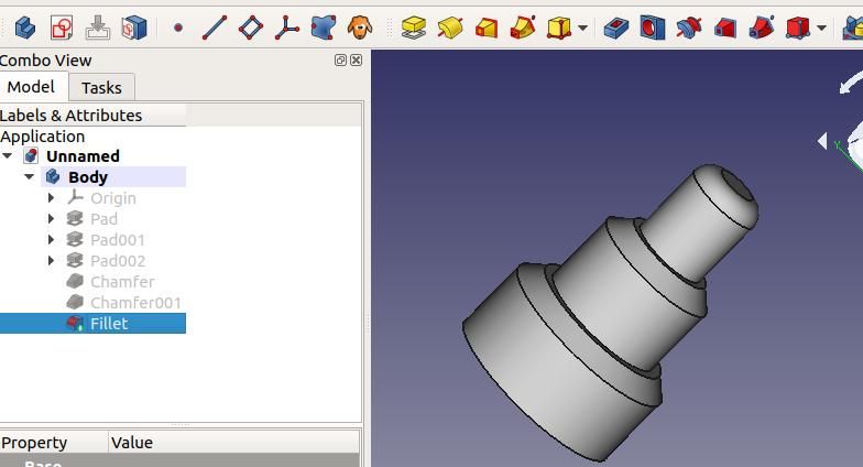
On the left-side of the FreeCAD window is a ‘Combo View’ Panel. The ‘Model’ tab lists the steps taken to create the model. It can be used to select and edit previous steps, to hide and reveal them, and to alter the stage’s appearance, including transparency. The ‘Tasks’ tab lists the tools that can be used at the moment. Using FreeCAD involves switching between these two lists.

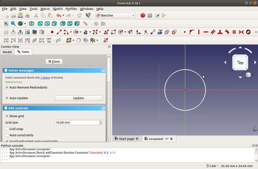
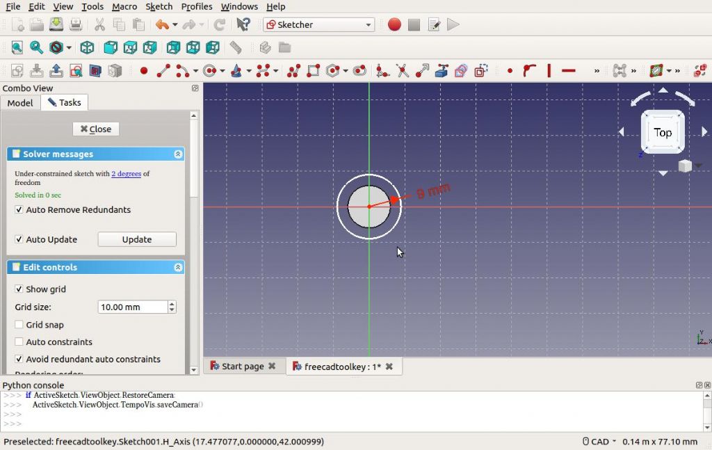
Using the Circle Radius Tool (which also draws diameters) draw a circle centred near the red dot in the middle of the grid. Don’t worry about the exact size and position; they are ‘constrained’ next.
Constrain the circle to the centre of the grid by clicking the mouse on the two red dots to select them. Once they are both Green click the button marked with the ‘Create a coincident constraint’ button ( Identified by a small red dot ). The circle should jump into position. It is locked in position.
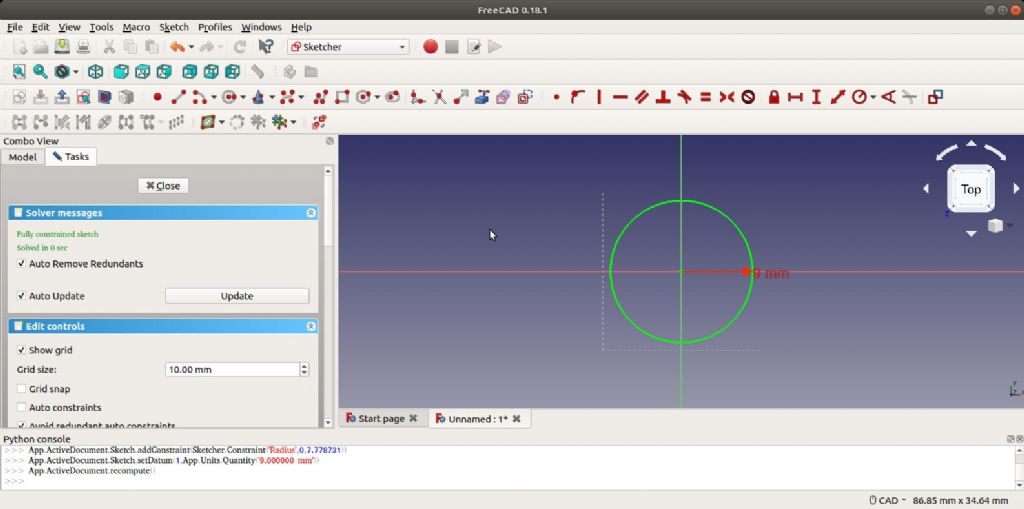
Select the circle by clicking on its perimeter. Then click the red ‘Constrain an Arc or Circle Button’ and set the radius to 6mm. Note the circle goes green. This indicates it is ‘Fully constrained’: it’s a circle of fixed diameter locked in position inside 3D space. It’s not floating about. By no means essential for sketches to be ‘Fully Constrained’ but I’ve found keeping things tight minimises trouble later. FreeCAD, like other 3D software can behave very oddly if a user’s model becomes internally inconsistent. Although this can be very difficult at first practice makes perfect – after a while, modelling becomes second nature. It’s important to obey the software package’s rules, it will absolutely not understand what you meant, only exactly what you told it to do.

Dave
Ronald Morrison.


