Making a Carriage stop for a lathe

Advert

Making a Carriage stop for a lathe

Home Forums The Tea Room Making a Carriage stop for a lathe

Viewing 15 posts - 51 through 65 (of 65 total)
  • Author
    Posts
  • #588294
    Dalboy
    Participant
      @dalboy
      Posted by Terry Kirkup on 02/03/2022 20:21:51:

      Here's mine. I thought I'd avoid any flack by not showing the 45 second video I didn't make of me drilling and tapping one 8mm hole. smiley

      img_20210114_163748.jpg

      I have the very same one did need to strip it and clean it up for the adjuster to operate smoother than supplied

      Advert
      #588307
      ega
      Participant
        @ega

        Greensands:

        That's a very nice looking machine and ingenious solution.

        On mine, the corresponding hole is for the detent grub screw ie FWIW not an oiler.

        #588313
        Nigel Taylor 2
        Participant
          @nigeltaylor2

          Saddle Stop 2.jpg

          I modified the stop on my Warco 290V to make it quick to set and release.

          Saddle Stop 1.jpg

          #588323
          Dalboy
          Participant
            @dalboy

            Very nice Nigel may have to do that with mine looks easier than having to fiddle with the two bolts underneath the stop assembly

            #588335
            Nigel Taylor 2
            Participant
              @nigeltaylor2

              In case it's not clear from the photos, I used the quick release mechanism from a bike front wheel to make the clamping mechanism. Much easier than two hidden bolts!

              #588342
              Steviegtr
              Participant
                @steviegtr
                Posted by Greensands on 05/03/2022 15:26:47:

                This is my answer to a gearbox fitted Myford S7 making use of the tapped hole provided for the oiler. It has provided satsfactory service over many tears.

                Hi again Greensands. I have been working on my Myford tonight. If i had the stop where yours is fitted , then i could not engage backgear.

                Steve.

                #588343
                Nick Wheeler
                Participant
                  @nickwheeler
                  Posted by Derek Lane on 05/03/2022 19:41:21:

                  Very nice Nigel may have to do that with mine looks easier than having to fiddle with the two bolts underneath the stop assembly

                  One of my requirements for this sort of thing is that tools are not needed for use. I've posted my current stop, but having made it from aluminium it's spread and becoming less effective. And I've never used the adjustable stop because it's not accurate.

                  So the new one will look like this:

                  carriage stop v1.jpg

                  and

                  exploded carriage stop.jpg

                  #588353
                  Steviegtr
                  Participant
                    @steviegtr
                    Posted by Nicholas Wheeler 1 on 05/03/2022 22:08:49:

                    Posted by Derek Lane on 05/03/2022 19:41:21:

                    Very nice Nigel may have to do that with mine looks easier than having to fiddle with the two bolts underneath the stop assembly

                    One of my requirements for this sort of thing is that tools are not needed for use. I've posted my current stop, but having made it from aluminium it's spread and becoming less effective. And I've never used the adjustable stop because it's not accurate.

                    So the new one will look like this:

                    carriage stop v1.jpg

                    and

                    exploded carriage stop.jpg

                    Mm interesting. Will like to see the finished product.

                    Steve.

                    #588369
                    Dominic Bramley
                    Participant
                      @dominicbramley60728
                      Posted by Nicholas Wheeler 1 on 05/03/2022 22:08:49:

                      Posted by Derek Lane on 05/03/2022 19:41:21:

                      Very nice Nigel may have to do that with mine looks easier than having to fiddle with the two bolts underneath the stop assembly

                      One of my requirements for this sort of thing is that tools are not needed for use. I've posted my current stop, but having made it from aluminium it's spread and becoming less effective. And I've never used the adjustable stop because it's not accurate.

                      So the new one will look like this:

                      carriage stop v1.jpg

                      and

                      exploded carriage stop.jpg

                      I like the look of this design. Grab a couple of pics if/when you make it and it could be a good little article for MEW….

                      Dom

                      #588391
                      Bob Unitt 1
                      Participant
                        @bobunitt1

                        Here's the Carraige Stop I made for my Myford 254. No automatic lathe-stopping or anything, it's mainly to prevent me running into the chuck when roughing-out by hand. No changes made to the lathe itself, it just clamps around the top and bottom of the ways. It consists of a holder with a clamp on the lathe centre-line, with 4 different length rods (adjustable) to set the actual stop position (which acts on the centre of the saddle).

                        First picture shows the holder with clamp, and the four stop-rods.

                        Second picture is a close-up of the holder.

                        Third picture is the carraige-stop in use, with the saddle stopped by it.

                        dscf4184.jpg

                        dscf4183.jpg

                        dscf4187.jpg

                        #588410
                        john halfpenny
                        Participant
                          @johnhalfpenny52803

                          A simple adjustable stop on my Clarke lathe. The excess length disappears into the drive housing on the left. Next job is to add a fine thread button/lock nut at the contact end.

                          20220224_104654.jpg

                          #588437
                          KWIL
                          Participant
                            @kwil

                            Greensands.

                            "This is my answer to a gearbox fitted Myford S7 making use of the tapped hole provided for the oiler. It has provided satsfactory service over many tears."

                            That boss is for the Locating pin for the Quadrant Plate controlled by the Upper Lever for QCGB selection, not an oiler.

                            Does your fixing screw for your device still load the locating pin spring below?

                            #588466
                            Greensands
                            Participant
                              @greensands

                              Hi KWIL The fitting has been in place for so many years that I had forgotten all about the exact details, Without removing the unit I would have said that the answer to your question is no and certainly there have been any issues with the stop in operation. The strange thing however is that my copy of the Myford Handbook for the S7 Ref No.S723W entitled "Notes on Operation Installation and Maintenance Also Pictorial Parts List" ,- Section: Quick Change Gearbox – pages 50-52 makes (or shows) any mention of the boss to which you refer. The same is also true with my copy of the separate Myford publication No.712U for the QC Gearbox. Do you have any further information for the quadrant plate locating pin?

                              #588490
                              KWIL
                              Participant
                                @kwil

                                I have 2 x S7s with QCGB. My details are correct. No mention is made of the boss, but all the parts below are used at that location. Does the quadrant still "latch" when going A – B  C when selecting using the Chromed lever?

                                Part 193 is the Quadrant Plate

                                198 is the spring, 199 is the pin which bears on the quadrant. You took out Grubscrew, part 200 to fit your device.

                                All details on page 51 of S723W


                                Regards

                                K

                                Edited By KWIL on 06/03/2022 19:02:40

                                #589093
                                Hopper
                                Participant
                                  @hopper

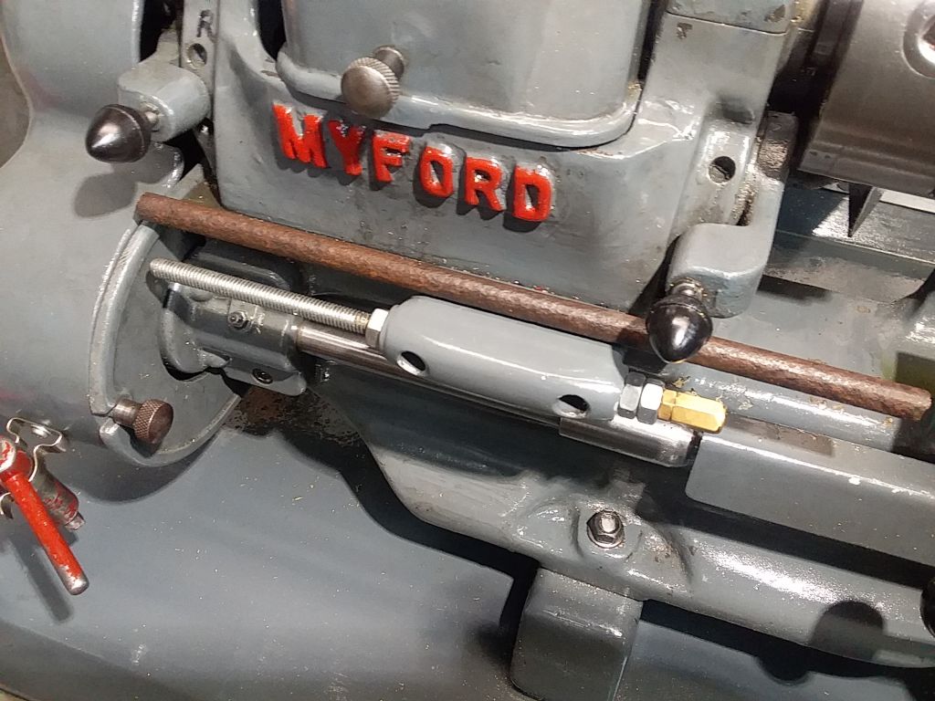
                                  Well, all the excellent examples in this thread have shamed me into upgrading my "permanently temporary" stop with the threaded rod and nuts. So have made a plain rod and a GH Thomas style ball handle and brass cotter clamps bring it up to snuff. A bit more forgiving in the event of a crash as pointed out, and looks better than that bright zinc plated hardware store threaded rod. And its much quicker action to set than faffing about with nuts and spanners. So now I can whiz it out of the way to get the oil gun into that leadscrew oiler at the left.

                                  The finished unit

                                  stop new


                                  The parts:. Making the ball handle is always an interesting exercise but very satisfying when it's done.

                                  stop parts


                                  The naff old threaded rod, and the nasty piece of rusted 3/8" bar I had to turn down to 5/16" for the job. Our only steel merchant here does not stock bright mild steel bar under 1/2" and shipping is too costly to buy online so it was out with the moving steady and a big dose of patience. No matter how you set it up, that steady gets in the way, of the tailstock, of the chuck, of the toolpost, of the bolts on top of the toolpost. Eventually turned the first inch or more down to size then set the tool ahead of the steady so the steady followed on the nicely machined surface, not that awful rusty surface ahead of the cut.

                                  stop old


                                  Edited By Hopper on 10/03/2022 10:40:15

                                  Edited By Hopper on 10/03/2022 10:42:38

                                  Edited By Hopper on 10/03/2022 10:47:23

                                Viewing 15 posts - 51 through 65 (of 65 total)
                                • Please log in to reply to this topic. Registering is free and easy using the links on the menu at the top of this page.

                                Advert

                                Latest Replies

                                Home Forums The Tea Room Topics

                                Viewing 25 topics - 1 through 25 (of 25 total)
                                Viewing 25 topics - 1 through 25 (of 25 total)

                                View full reply list.

                                Advert

                                Newsletter Sign-up