Machining Crankshaft

Advert

Machining Crankshaft

Home Forums Beginners questions Machining Crankshaft

Viewing 25 posts - 1 through 25 (of 40 total)
  • Author
    Posts
  • #83947
    JOHN BRIDGE 1
    Participant
      @johnbridge1
      I am attempting to build a Stuart Twin Launch engine and so far so good, I now want to machine the crankshaft what sort of cutting tool do I need to machine the center main bearing there is about 500 thou. between the two big end webs should the tool look something like a parting off tool. To machine the big end jounals do I need to level the shaft up in a four jaw or should it be machined between centers by making some sort of offset for the big end to rotate on the Lathe center.
      Advert
      #5925
      JOHN BRIDGE 1
      Participant
        @johnbridge1
        #83948
        Kevin Bennett
        Participant
          @kevinbennett25223
          Hi I had several attempts to make my Stuart twin crankshaft from solid in the end I fabricated it with gauge plate and silver steel.
          i have 2 scrap ones i can send you
           
          good luck Kevin
          #83952
          Speedy Builder5
          Participant
            @speedybuilder5
            When I made a 5″ twin, I was advised to leave each end of the bar on at full diameter, and mark and centre drill the centers for each journal and the centre of the main journal. Then you just turn each journal between centres. You will need a great big lump of lead to balance the setup – make this out of folded lead sheet so you can easily chop off a bit to get the balance and hold it onto the chuck with some long jubilee clips – or two or three joined together(get biguns from a logstove centre or boat shop). You end up with a crankshaft with a big washer at each end which can be used for the output shaft(s) once the big ends were finished. Another tip was to remove as much material by milling it away, but I didn’t do this.
            Mind you it did make the Boxford rattle a bit. I was using normalised En8 and carbide tooling. Between the webs, I made an extra long tool and mounted a carbide tip on the end of it.
             
            Plenty of coolant and elastoplast for the burns on your hands. Good luck

            Edited By Robert Humphrey on 05/02/2012 16:50:37

            #83953
            JasonB
            Moderator
              @jasonb
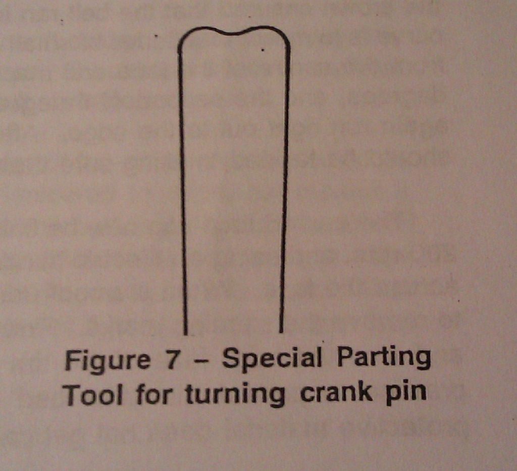
              Yes something like a parting tool with the outer corners radiused and the middle of the cutting edge hollowed out to reduce the amount of chatter.
               
              J
              #83958
              Richard Parsons
              Participant
                @richardparsons61721

                John do a search on this site for V12 as the keyword. Pick Mr Worland’s post and follow the link. At about 1minute in you will see just how the builder did it more than once. You see the the tools used etc.
                Good Luck
                Dick

                #83974
                JasonB
                Moderator
                  @jasonb
                  This is a good detailed post of machining a stuart double throw crank, he also has details of the rest of the engine. While you are there check out his “Golden No1”
                   
                  J
                  #83986
                  John Bentley
                  Participant
                    @johnbentley76104
                    Hi John – I’d vote for making simple fixtures and turning between centres. I did one Twin Launch and one Compound that way, using a round-ended version of a parting tool. Keeping the tool razor sharp, setting the height precisely and taking light cuts are probably the key to a trouble-free job. I might suggest that you don’t take a cavalier attitude toward the dimensions of the crankshaft (the journal and web widths and locations). Obviously the sides of the webs are used as the thrust portions of the main bearings in this engine, so the shaft fits into the base like the last piece of a jigsaw puzzle. A flexible overhead lamp is the most important tool – you need good light coming from the correct angle for each surface as you are cutting. It really isn’t a difficult task… looking back it was much easier than milling the top surface flat on the gunmetal soleplate (I didn’t like that job too much!).
                    Best of luck – I hope we will get to see a picture of your finished crank. -John


                    #83988
                    JOHN BRIDGE 1
                    Participant
                      @johnbridge1
                      Thanks for all your help the pic shows what I am trying to do, I have done the bit shown and removed the part where the two halves where joined together. I now want to machine the this part of the shaft to the correct diameter but cannot see how to do it with the tool shown. It seems the tool has not enough sideways movement before contacting the webs.
                      #83992
                      JOHN BRIDGE 1
                      Participant
                        @johnbridge1
                        Hi John, Sorry I? did not read your post before I posted my pic. your referance to the parting tool is what I am after, I do realise the importance of getting the shaft spot on.
                        John
                        #83996
                        Ady1
                        Participant
                          @ady1
                          If I get a situation like that I just bring the tool in at an angle, sideyways.
                          Nice light cuts with a well honed tool
                          You won’t get a perfect square edge but you can always finish off with a file
                           
                          For all that there is left to do, doing it all with a file would be a lot safer.

                          Edited By Ady1 on 05/02/2012 22:01:22

                          #84001
                          John Olsen
                          Participant
                            @johnolsen79199
                            Hi john,
                             
                            Apart for the general problem of machining a crankshaft, you are also up against a possible specific problem here with the actual part that Stuarts supplied. As can be seen in your picture, the crankshaft supplied is actually two forgings which have been welded together in the middle with the throws at right angles. The problem that I had with this with a Stuart Double Ten was that the weld material was harder than high speed steel, and even carbide did not seem happy trying to cut it. So what I did in that case was put the Stuart one aside and make another from a big piece of free cutting bar. Yours may not have this problem…mine was too old for me to consider returning it to Stuarts, someone had had the set of castings for years.
                             
                            Another point is that the parting tool you show does not have enough reach. Rather than being a piece of square HSS with the parting too ground on the end, it wants to be a blade type of parting tool, so that you can extend the tool far enough to reach into the journal and be able to traverse across without fouling on the webs at either side. It also wants to be very narrow, eg 3/32 rather than 1/8. I also grind a little V down the tip for this job, so that the corners do most of the cutting.
                             
                            Next, a crankshaft like this is very springy, and the pressure from the centres is trying to collapse it. So you want to provide support at the webs where you are not machining, eg in this case at the crank throws. A good way to do this is to clean up the web a little with a file and put a short bolt through with a washer on each side. need a picture for this really…the bolt will be in the gap where the shaft is interrupted so that it can help take the endload from the centres.
                             
                            Finally, the way I do crankshafts like this is to do as much roughing out as possible between centres in the mill. To do this you need a vertical mill (of course) plus some way of supporting the job between centres on the mill. I have a Vertex dividing head and tailstock now, which is ideal, but I have done small shafts on the Unimat 3 using the milling attachment. Using a slot drill, long series if necessary, you can rough out most of the material without the cutting loads being anything like as high as they will be with turning. You still need to finish the journals in the lathe as the milling will not give a wonderful finish. (Grinding would be nice but I am not set up for that!) I did an article on this back when I used to write for Model Engineer, you would be welcome to a copy.
                             
                            regards
                            John
                            #84002
                            John Bentley
                            Participant
                              @johnbentley76104
                              Hi John – What I forgot to mention was that I used two tools – a left hand and right hand version. However a tool like the one in the picture, but ground back a bit farther looks like it would clear the webs for the entire job. As far as the shaft dimensions are concerned, you can absorb a little error if you haven’t machined the bearing sides yet – I was only advising against wanton disregard for the numbers.
                              John
                              #84005
                              Ady1
                              Participant
                                @ady1
                                If it’s harder than hss maybe a small grinding tool would get in there, would be better for the finish too
                                 
                                I got a load of small cheap ones from fleabay years ago
                                 
                                Look at “assorted grinding wheels” on fleabay, the thinner ones are usually 50mm or 65mm by 6mm but you can always dress one with an old carbide tool.
                                #84006
                                JOHN BRIDGE 1
                                Participant
                                  @johnbridge1
                                  John Olson, Hi John Thanks for your reply, the picture is not of my crankshaft but it is the same as mine and the tool I am using is narrower but I am still having problems, my casting kit was bought by a dear friend in 1975 he is no longer with us so I would not have much success at getting it replaced I think, I would like a copy of your article please.
                                  John

                                  Edited By JOHN BRIDGE 1 on 05/02/2012 22:46:32

                                  #84007
                                  JOHN BRIDGE 1
                                  Participant
                                    @johnbridge1
                                    John Bently, Hi John, Thanks for your reply, I was thinking along those lines of the two tools and also about the bearing sides which I have left for this reason, I think I know what I have to do now.
                                    John
                                    #84008
                                    MICHAEL WILLIAMS
                                    Participant
                                      @michaelwilliams41215
                                      Stuart Turner in their factory at Henley on Thames used to machine the journals for their supplied finished crankshafts entirely by grinding . They did this on an industrial size Jones and Shipman grinder . There are pictures and description of this being done in old catalogues . The advantage of finishing journals by grinding is that , done with care , there is very little load on the crankshaft to cause whipping or chatter .
                                       
                                      MW

                                      Edited By MICHAEL WILLIAMS on 05/02/2012 23:05:09

                                      #84009
                                      JOHN BRIDGE 1
                                      Participant
                                        @johnbridge1
                                        Ady1, Thanks for your reply, how would I use a grinding wheel in my lathe a ML7.
                                        John
                                        #84010
                                        Ady1
                                        Participant
                                          @ady1
                                          I actually had a go at a small 4way crankshaft in steel tonight…what a nightmare on a lathe.
                                          ding ding ding…na…there’s got to be a better system.
                                          I’m going to have a go on a shaper, with a strong dividing head system via my vice, a baby crankshaft is small enough to fit into it.
                                          …an intruiging problem.
                                           
                                          With teeny stuff there would be problems presenting the grinding wheel into the crankpin and maintaining good stiffness for either the crank or the grinding wheel…you can’t scale nature…
                                           
                                          So maybe an hour or so with a diamond grit file to clear the rough crankpin bits, then a final cut with a decent parting tool on the lathe would be a better idea…it’s not like you’re doing a lot of them, you’re just finishing one off.
                                          Or invest in a carbide parting tool, and use gentle cuts.
                                          Carbide would probbly solve all your problems, it’s amazing stuff, and you would find other uses for it whenever hss struggles.

                                          Edited By Ady1 on 06/02/2012 00:54:06

                                          #84013
                                          Brian Dickinson 2
                                          Participant
                                            @briandickinson2
                                            Why not use a tangential tool. Its like a parting tool with a leg which goes down to the cross slide bed. They can be very thin and if it’s kept sharp you only need the one.
                                             
                                            Bri
                                            #84015
                                            JasonB
                                            Moderator
                                              @jasonb
                                              Take most of the material away with left & right hand tools then as I said above grind up an Eclipse type parting blade as the pic below.
                                               

                                              This gives radiused corners for strength and the hollow on teh front reduces chatter, work the tool from side to side with very light cuts. May need a bit of stoning to get both sides cutting the same.

                                               
                                              I visited one of our other members last week and he showed me a tool he had made to turn the crank for a 4″ traction engine. It was a hefty lump of 1.5″ x 0.5″ bar on edge and in each corner he had mounted two small circular replacable carbide inserts which act just like the tool above but massivelty rigid.
                                               
                                              J
                                              #84018
                                              John Olsen
                                              Participant
                                                @johnolsen79199
                                                There are a lot of us called John on this thread aren’t there.
                                                 
                                                Grinding would be a really nice way to finish a crank, however most of us are not well set up for it. Ideally you want a good toolpost grinder, and you want to be a bit careful about it since you don’t really want to end up with grinding dust all over the ways. You would also need the right wheel, eg narrow enough to fit between the webs, and the means to true it up as it wears. Scaling nature is not too much of a problem with grinding, since the cutting loads are actually very small, so the job has less tendency to deflect and the rigidity of the machine itself is not likely to be a problem. Ok if a suitable toolpost grinder and a selection of wheels is available.
                                                 
                                                The idea of milling away as much as possible has the same advantage as grinding, the cutting loads are less than for turning (but more than for grinding) so the load induced deflections of the job are less. Again however we do need the right equipment for the job. This means a vertical mill with some means of mounting the crank between centres. This does not need anything too fancy, especially for small ones like this, I have done one for a Stuart Double ten on the Unimat, and in that case the rotation of the workpiece was controlled by hand with some friction added to help control things. This was with the job suspended between centres on the lathe bed, and the milling attachment mounted on the cross slide. A similar thing could be done on the Myford if a Unimat milling attachment could be borrowed, eg mount the Unimat attachment on the Myford cross slide. It looks a bit sdcary when you set it up, but the cutting loads are low enough and you can controllably take away most of the material this way. The only trouble is you won’t get a good enough finish to run a bearing on, so you have to finish in another way. But since it is all done between centres, you can transfer to the lathe for some fine finishing cuts.
                                                 
                                                For turning on these small cranks, what we are up against is that the parting tool, even modified above, needs to be wide enough to not deflect sideways too much, and narrow enough not to cause us problems with the cutting load. No doubt we have all seen how a parting tool can cause problems in a less than rigid machine, well these little crankshafts are inherently less than rigid, and so too wide a tool will try to dig in, which can lead to disaster. I would actually use three tools if I was taking it all out with turning, a narrow left hand tool, a narrow right hand tool, and one like the diagram above for finishing.
                                                 
                                                Anyway, I will scan the article, if you like to send me a personal message with your email address I will send it to you. (Don’t put your email address in a normal posting!)
                                                 
                                                regards
                                                John
                                                 
                                                 
                                                #84023
                                                MICHAEL WILLIAMS
                                                Participant
                                                  @michaelwilliams41215
                                                  Long , thin and delicate components are routinely ground on standard industrial grinders with little or no support other than at the ends . With a proper control system , manual or CNC , the grinding can be arranged so that there is only a very small force acting on the component at the point of grinding . Why this is so has been dealt with in part in an earlier post about toolpost grinders .
                                                   
                                                  This very small force with grinding contrasts greatly with the situation using turning tools where there has to be a relatively high applied force just to make the cutting action start and with even a fine cut large additional forces are generated .
                                                   
                                                  The grinding wheel that Stuart Turner used in demonstrating the grinding of the centre bearing of a double 10 was about 8 inches diameter and about 3/8 inch wide – and this was on a tiny component only held at one outboard end in a collet .
                                                   
                                                  MW
                                                   
                                                   
                                                  #84024
                                                  Ady1
                                                  Participant
                                                    @ady1
                                                    The idea of milling away as much as possible has the same advantage as grinding, the cutting loads are less than for turning
                                                    That does seem to be the best system for hogging out most of the material, the shaper would be more fiddly.
                                                     
                                                    The other problem is stiffness between the centres, you need to squash the workpiece between centres, which becomes a big issue as you hog out more material.
                                                     
                                                    Perhaps holding the workpiece between two four jaw chucks would be better, certainly it would be less stressful
                                                    If you only move a single jaw on the 4 jaw when revolving the workpiece for the next offset crankpin, so you reposition the WORKPIECE, and don’t move 3 jaws, then you will get…well moderate concentricity
                                                    The original setup between 4 jaws will need some dial indicator work.
                                                     
                                                    I made a revolving centre for my chucks to fit on the tailstock(great for hogging down wonky bars of metal), a smaller one would be more sensible, you can see the general thinking.
                                                    Thats a three jaw in the tailstock example, obviously I would use a good small 4 jaw…if I could afford one.
                                                    So with a good quality revolving centre in the tailstock you have stiffness and security, but very little crushing force on the workpiece.
                                                     
                                                    Final high accuracy finishing work with light cuts and a carbide quality parting tool can still be done between the centres
                                                     
                                                     
                                                    2cents

                                                    Edited By Ady1 on 06/02/2012 11:14:00

                                                    #84026
                                                    Ady1
                                                    Participant
                                                      @ady1
                                                      For positioning the workpiece a centre which protudes only slightly from the middle of the 4 jaw body would make setting and resetting the job miles easier.
                                                       
                                                      This photo is obviously not what I mean, each 4 jaw would have a specially made centre where the workpiece could be positioned easily between these centres, and then the 4 jaw chuck jaws secure the workpiece in position
                                                      Saves messing about checking stuff once the initial work for the holes for the offset centres have been done.
                                                       

                                                      To get the holes set accurately at each end I would do one end, then make a template of the first end, which I would transfer to the other end for marking out.
                                                      That would be pretty fiddly and need some thought though…The holes at the opposite ends really do need to be spot on.
                                                      Maybe better men than me could help out here, since these holes are quite critical for accuracy and a good crankshaft
                                                       
                                                       
                                                      Sooo
                                                      Set your holes up properly
                                                      hog out most of the material with a small milling cutter
                                                      finish off with a good parting tool
                                                       
                                                      Seems to be the easiest system for an amateur
                                                       
                                                    Viewing 25 posts - 1 through 25 (of 40 total)
                                                    • Please log in to reply to this topic. Registering is free and easy using the links on the menu at the top of this page.

                                                    Advert

                                                    Latest Replies

                                                    Home Forums Beginners questions Topics

                                                    Viewing 25 topics - 1 through 25 (of 25 total)
                                                    Viewing 25 topics - 1 through 25 (of 25 total)

                                                    View full reply list.

                                                    Advert

                                                    Newsletter Sign-up