Load reactors for VFDs

Advert

Load reactors for VFDs

Home Forums Electronics in the Workshop Load reactors for VFDs

Viewing 21 posts - 1 through 21 (of 21 total)
  • Author
    Posts
  • #567044
    Andrew Tinsley
    Participant
      @andrewtinsley63637

      I am interested in using a load reactor between a VFD and a very old 3 phase motor.

      I understand that a load reactor will reduce the nasty spikes that would normally get to the motor. Not sure if I have this correct?

      The motor is a special to some very old kit. I could get it rewound to modern standards or use a load reactor to reduce the stress on the motor. The existing VFD powers the motor without any problems but I suspect that will not last long!

      I also suspect that line reactors are probably as expensive as a rewind. Anyone got experiences they would like to share?

      Andrew.

      Advert
      #32217
      Andrew Tinsley
      Participant
        @andrewtinsley63637
        #567045
        John Haine
        Participant
          @johnhaine32865

          I think that the motor is more likely to generate spikes itself rather than the VFD. I think that spikes will occur because of leakage inductance in the motor windings, which might overstress the VFD semis or the motor insulation, or both. Adding series inductance would surely make spikes worse as in effect it's adding leakage inductance? It might be possible to mitigate spikes with some small shunt capacitors (suppressions caps) provided you get them with a high working voltage. Before trying this do you have a 'scope to see if there are any spikes in the first place?

          #567089
          Mark Rand
          Participant
            @markrand96270

            Couple of points:-

            1. The motor won't generate spikes due to leakage reactance or anything else.
            2. adding series reactance won't increase spikes.
            3. Adding parallel capacitors to VFD output in contra-indicated.

            Other than that, a sine wave filter (series reactor followed by parallel capacitors will reduce any whining from the motor and reduce any spikes. I use one on the output of the inverter that feeds my workshop.

            #567096
            Ian P
            Participant
              @ianp

              Does 'Contra indicated' in your third point mean that one should not put capacitors on the VFD outputs? (I wasn't thinking of doing it)

              Does the sine wave filter operate over the full frequency range of a typical VFD?

              Ian P

              #567102
              old mart
              Participant
                @oldmart

                VFD's can be programmed to give a very slow gentle start and also slow stop, wouldnt this be adequate to run your old motor?

                #567105
                Robert Atkinson 2
                Participant
                  @robertatkinson2

                  I agree with what Mark Rand said. I'd add a couple of comments / questions.

                  Are you using the the VFD to increase the speed of the motor? If you are this is more likely to stress the insulation in the motor. A VFD typically increases the output voltge with spped to maintain the current. If you are jut doing single to 3 phase with the VFD it is not an issue.

                  What VFD are you using? what does the manual say about load reactors?

                  While specific motor drive reactors are expensive, they are nothing special. Just 3 inductors of suitable value and current / voltage ratings. The value depends on the VFD PWM frequency. For just transient suppresion a lower value may be adequate.

                  Robert G8RPI.

                  #567108
                  Andrew Tinsley
                  Participant
                    @andrewtinsley63637

                    I have several VFDs I can use, Siemens, Fuji, Telemecanique and Hyundai. I can check on what each manual has to say about load reactors.

                    Having looked at VFD voltage outputs on a scope, they are anything but sinusoidal and I am sure that driving a very old 3 phase motor from such a source will be putting more stress on it than using genuine 3 phase supply.

                    I seem to have read somewhere that a load reactor will produce a much more sinusoidal output, which I suspect will be much kinder to the motor. Not sure if this is true or a figment of my imagination!

                    The motor will only be operated at 50 Hz.

                    Andrew.


                    Edited By Andrew Tinsley on 16/10/2021 21:44:49

                    #567122
                    Anonymous

                      Spikes would generally be regarded as unwanted artifacts. A VFD doesn't inherently generate spikes. The output of a VFD is a PWM signal where each pulse varies in width on a cycle by cycle basis according to a sinusoidal function. The motor inductance is normally used to create the wanted sinusoidal current.

                      The PWM pulses have fast edges which leads to a large number of harmonics. There are concerns that the fast edges and high harmonic content can be bad for some motors.

                      A reactor is simply a LC lowpass filter. It filters out the pulse rate frequency and harmonics, leaving just the sinusoid. Since the pulse repetition rate should be a much higher frequency than the underlying sinusoid a simple filter will remove the higher frequency components, while leaving the sinusoid, over the full range of the VFD output frequencies. Given there are two reactive components the filter characteristic will fall off at about 40dB/decade.

                      Reactors are not cheap. The inductor needs to be fairly large, in terms of inductance, but also needs to carry the full load current so is physically large.

                      Andrew

                      #567126
                      John Sykes 1
                      Participant
                        @johnsykes1

                        Andrew (T): could you give details of the motor (namplate) and how you intend to operate it? Old (quality) motors are generally quite robust and have some design margins to cope with over-voltage etc.

                        The principle issues to look out for when operating from a VFD are

                        – over-heating if continuously run well under normal speed ( fan cooled)

                        – increased iron losses due to the high frequency switching , so again a thermal issue.

                        I would say you'll be fine, but if you have some power in reserve and wish to take a conservative approach, set the VFD parameters to output full voltage at, say 55Hz: this will then run the motor 10% under-voltage at 50Hz and reduce the iron losses.

                        John


                        Edited By John Sykes 1 on 17/10/2021 10:20:06

                        #567127
                        Andrew Tinsley
                        Participant
                          @andrewtinsley63637

                          Thanks Andrew,

                          You have confirmed what I thought and remember reading re load inductors. As you rightly say they are an expensive item. although I don't see why they are so expensive.

                          I am just finishing off the mechanics of a coil winder , so I can wind my own. Anyone any suggestions as to how to calculate the required inductance? Most load reactors laminations are like those usually seen on 3 phase transformers. Is there any reason not to use a lamination stack for each of the 3 inductors. I ask simply because I have a large supply of such laminations.

                          Andrew.

                          #567131
                          Andrew Tinsley
                          Participant
                            @andrewtinsley63637

                            Thanks for your input John, The motor is from the pre war period. It drives an Alfred Herbert high speed drill which I have restored. I am finally getting round to sorting out the drive for the motor.

                            For what it is worth, the motor plate says Alfred Herbert Ltd, 1/3 HP, 400/440 volts, 3 phase 50 cycles. The motor type is an SA 53. I have dug out the star point and is now wired in delta.

                            As one would expect from an 85 year old motor, it is massive. I need to retain the motor because the top end plate is a large casting which has an extension that is part of the sliding belt tensioning system and so the motor is unique to the drill.

                            I do not want to butcher the drill by fitting a new motor. I am looking on the drill as a museum piece, which can be used in anger on the odd occasion. Its early use was in the manufacture of Merlin magnetos in a Leicester shadow factory. The drill has an air ministry plate and also a BTH brass plate (BTH ran the factory for the Air Ministry)

                            If and when the motor fails, I shall get the motor rewound to modern standards of insulation. but obviously I hope to put off the day when it fails.

                            Andrew.

                            #567134
                            John Sykes 1
                            Participant
                              @johnsykes1

                              Personally I would forget the filter and just run it at the lower end of the name-plate rating, i.e. 230V delta. With all that mass it will take a long while to get hot!

                              John

                              #567138
                              MK_Chris
                              Participant
                                @mk_chris

                                Andrew T.

                                Not a direct answer but a reminder of your previous post. Title :- Earth Leakage on a 3 phase Motor : post date 31/12/2020. Includes my experience with a 3 phase sine filter supplied with my VFD
                                It drives a Pultra Mardrive motor circa late 1940's / early 1950's and set with 7 second slow start.

                                All is still working well (fingers now firmly crossed).
                                Not a direct answer but it might help your thinking.

                                Chris.

                                #567146
                                SillyOldDuffer
                                Moderator
                                  @sillyoldduffer

                                  Posted by Andrew Tinsley on 17/10/2021 10:25:58:

                                  I am just finishing off the mechanics of a coil winder , so I can wind my own. Anyone any suggestions as to how to calculate the required inductance? Most load reactors laminations are like those usually seen on 3 phase transformers. Is there any reason not to use a lamination stack for each of the 3 inductors. I ask simply because I have a large supply of such laminations.

                                  Andrew.

                                  You will need an Iron Core to make the inductor reasonably small physically!

                                  I'll have a go at the calculation: the formula are correct but I've made a big assumption about the impedance of the motor. Also, I am famously error prone when it comes to maths!

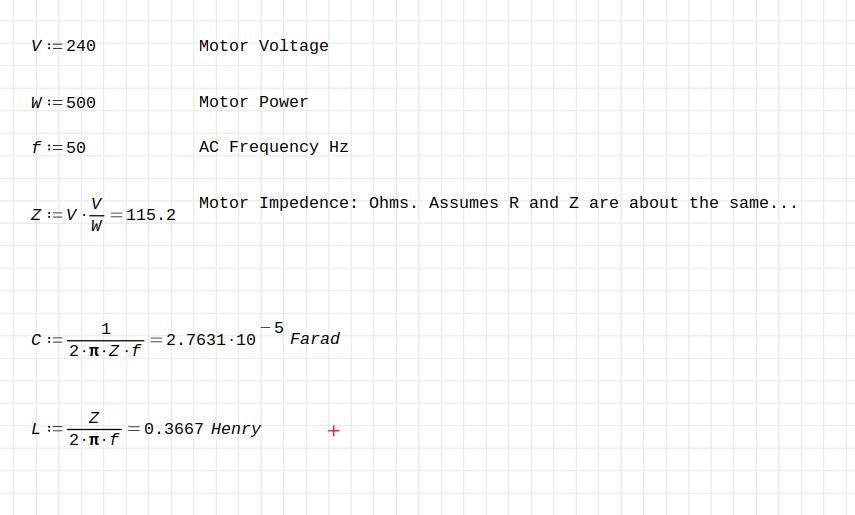
                                  50hzlc.jpg

                                  A simple Butterworth Filter is as simple as it gets – an inductor in series with a capacitor. Inline they make a bandpass filter, that is frequencies above and below 50Hz are filtered out.

                                  The calculation assumes a motor consuming 500W from a 240V source, and that the impedance of the motor is the same as it's DC resistance R=E²/W.   Trouble is impedance is the sum of reactive components, and a motor is mostly inductive, with a dash of capacitance. Better to measure the motor's actual impedance at 50Hz, and I think it will be found to vary with load, which complicates filter design.

                                  However, the sum above suggests 27uF and 0.4H.

                                  The reason reactors are expensive is 0.4H is a lot of turns, and the copper has to be beefy enough to take the current without overheating, here a few amps. The reactor is a fairly hefty lump of metal and three of them are needed, £££.

                                  John Sykes mentions a couple of problems with old motors and VFDs, but not the worst, I think. It relates to the design of the bearings and how they deal with earth leakage currents. Basically, old motors earth through the working part of the bearings, and this causes spark erosion. The effect is quite small when the motor is fed generated 3-phase, but the sharp edges of VFD generated 3-phase cause voltage spikes when the bearing sparks. The spikes worsen erosion and also stress the motor's insulation. Unfortunately, the insulation of older motors is poor by modern standards, and a duff bearing is likely to punch holes in it.

                                  Apparently pretty much all motors made after 1970 address the problem. If the motor was made before 1970, they become increasingly risky with age.

                                  Personally, old electric motors make me nervous, VFD or not. Although reassuringly big and well-made, behind the scenes the years are unkind to electrical insulation! So are overheating and damp conditions. A proper insulation test is needed to reveal if there's a problem.

                                  Dave


                                  Edited By SillyOldDuffer on 17/10/2021 12:52:44

                                  #567160
                                  Andrew Tinsley
                                  Participant
                                    @andrewtinsley63637

                                    Dave,

                                    The first thing I do with any motor is to megger the separate windings to earth using a 1000 volts DC and incidentally each winding to each other. That is before I even try to run them.

                                    Your warnings of all that can go wrong are precisely the reason that I was looking at load reactors.

                                    I too tried calculating values of capacitance and inductance and although my results are adrift from yours, I doubt that some of my basic assumptions are correct.. As you suggest , some measurements on the motor are really needed to have much confidence in the calculations!

                                    There is little to be done about the earth leakage via the bearings. I have changed them for new in any case as the motor is 2800 rpm. For the little use it will get, I doubt if this will be a real problem, rather more a theoretical one..

                                    The cost of the inductances are well nigh zero. I have a large amount of various diameter copper wire and stacks of iron E and I section for the cores. The only expense would probably be for the capacitors and I may well have some that would do the job.

                                    Unlike you, I am not too bothered about old motors, as long as they are well earthed then about the only real danger is destroying the rectifiers in the VFD. This isn't the end of the world either,as surprisingly I have found that a lot of the branded VFDs rectifier units are available and replaceable. I have already done this on a couple of blown VFDs that were given to me and one that expired on me!

                                    Thanks for your comments,

                                    Andrew.

                                    Edited By Andrew Tinsley on 17/10/2021 15:42:45

                                    #567162
                                    Andrew Tinsley
                                    Participant
                                      @andrewtinsley63637

                                      I forgot to mention that I have been running the drill on a Siemens inverter. Total running time is probably about an hour, so despite peoples worries that it may be a bag of nails, the motor has behaved with no problem. I have to say that it must be the coolest running motor I have come across. Must be the huge thermal mass of the beast.

                                      If a load reactor will keep the pwm, square wave, Fourier harmonics in check, then it will be a worthwhile precaution, especially as it will cost very little to construct.

                                      Andrew.

                                      #567182
                                      Mark Rand
                                      Participant
                                        @markrand96270

                                        If you dig into the sine wave filter link I posted, you'll find a page for chassis mount (non-enclosed) filters, which has a handy table of the inductance and capacitance that they use for various line currents:-

                                        **LINK**

                                        That seems to give a resonant frequency of about 3kHz, which is reasonable for a >4kHz VFD switching frequency.

                                        #567183
                                        Anonymous
                                          Posted by SillyOldDuffer on 17/10/2021 12:46:05:

                                          …….an inductor in series with a capacitor……

                                          A series capacitor? I think not, as it would need to carry full load current, equals expensive. All that is needed is a simple low pass filter, Butterworth or not. So series inductors and capacitors across phases, or to a common point which is essentially a star point albeit not connected externally.

                                          I'd be inclined to set the roll off frequency of the filter at 300Hz or so if the VFD is going to be set at 50Hz. The pulse rate should be well into the kilohertz so will still be filtered. If the frequency of interest (50Hz) is well below the 3dB point of the filter then there should be little mismatch between phases (in amplitude and phase) due to component tolerances and filter characteristics.

                                          There are two issues regarding the inductance. One, working out the value and two, designing an inductor with that value that will not saturate at rated current. The theoretical value is straightforward. Designing an inductor with that value will require knowledge of the properties of the laminations, in particular the permeability.

                                          Andrew

                                          Note: A Butterworth filter is simple, in the sense that it's pole only (no zeros) and the poles lie on a circle in the s-plane. It's beloved of text books and example sheets, but not used much in practice as it tends to use non-standard value components and has significant sensitivity to component tolerances.

                                          Edited By Andrew Johnston on 17/10/2021 20:27:33

                                          #567186
                                          Robert Atkinson 2
                                          Participant
                                            @robertatkinson2

                                            Hi Andrew,

                                            you said " The cost of the inductances are well nigh zero. I have a large amount of various diameter copper wire and stacks of iron E and I section for the cores. The only expense would probably be for the capacitors and I may well have some that would do the job "

                                            For your concerns I don't think you need a full sinewave filter. Just some series inductance. There are two many unknowns with th old motor to make an optomised solution. As you have some suitable parts I suggest you just make up 3 identical inductors with what you have. A core 3 or 4 inches square and around 3" stack thickness would be a good starting point. For 1/3 HP 1mm dia (18SWG, 0.8mmsq) would be conservative for current and limit th turns enough that it's unlikely to saturate. Just fill the first bobbin with neat winding. Keep count of the turns and don't over fill the bobbin. Put the same number of turns and laminations in the other two.

                                            This will be better than nothing and ony cost your time and the wire.
                                            For leakage currents you just need a small carbon brush on a spring pressing on the end of the shaft. Obviously this is connected to ground. A brush of a small DC or universal motor wuld be OK.

                                            Robert G8RPI.

                                            #567193
                                            Andrew Tinsley
                                            Participant
                                              @andrewtinsley63637

                                              Thanks everyone, especially Mark , Andrew and Robert. I think Robert has hit the nail on the head, three simple inductors, non optimised, is going to be the simplest solution . It would certainly get rid of most of the Fourier HF.

                                              I am sure that I was over thinking this one. It will only cost me time and will be better than running the motor direct from the VFD. Roberts suggestion of an earthed brush on the shaft is a good solution to the leakage current via the bearings. Although the very occasional use that the drill will get, probably doesn't even warrant the mod.

                                              It has been an interesting experience saving this old warhorse, I still can't get over the size and weight of the drill compared to modern designs. If the motor does eventually expire, I will get it rewound to modern standards.

                                              Thanks everyone, I am certainly more well informed on the topic than when I started.

                                              Andrew.

                                            Viewing 21 posts - 1 through 21 (of 21 total)
                                            • Please log in to reply to this topic. Registering is free and easy using the links on the menu at the top of this page.

                                            Advert

                                            Latest Replies

                                            Viewing 25 topics - 1 through 25 (of 25 total)
                                            Viewing 25 topics - 1 through 25 (of 25 total)

                                            View full reply list.

                                            Advert

                                            Newsletter Sign-up