The hydraulic motor should still work at that scale. Plenty of polishing will be required. 7 or 5 pistons.
wow if I'd known people were gonna draw it for me I'd put this one up.
This is is exactly what I am after. In the end the will be 60mm long and about 15mm wide.
Lol, I jest.
there are a few things that haven't been scaled down befor that I am attempting. Radio controlled diggers are usually made with electric track drive and slew motors but only one brand does 100% hydraulic and they use the other version of the rotary piston motor. So this is a challenge but love every minute of it.
The thrill is the build which is why my dream would be to start a business doing this but guess that will have to wait. Any how once the cad is mastered and the cnc no one will be able to control my engineering projects.
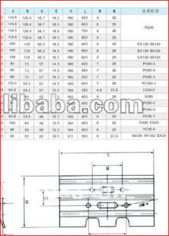
I had a quick look around – this document from a track pad manufacturer has some detail about profile and dimension which might be useful **LINK**
The profiles probably are not 'spot on', but are more for identification.
As others have mentioned, this would not be difficult to model in 3D – once you have got used to the software.
BTW – further to point raised earlier the Geomagic 30 day trial does do export of a wide range of 3D formats, and 2D – unlike some trial software export, printing, saving are all fully functional with. So you could have a go at modelling this using the trial, then save in formats that CAM might accept.
I did snip this yesterday has all teh dimensions, whats the full size of yours and I may have time later to draw it.
In the long run it will be better for you to draw the item as you can think through the machining process at the same time and not end up with a drawing of something that you can't make. It will also be easier if you want to make alterations.
I to find cad difficult / counter intuitive it depends greatly on which program you use.
But dont be put off cnc you can program cnc without cad cam quite easily depending on what program you are using.
Cad is great for keeping project drawings that may need updating or where you may need to work out a point on a drawing that is part of a compound angle or a length along arc. It is not a per-requiste to program cnc. Most of the industrial cnc operators ive known learnt cnc first then picked up cad at a later as an interest if at all.
I programed a part shown below last week and it was far less than 64,000 lines.
I am not what i would call a skilled machinist my back ground is machine tool maintenance for engineering works. At the moment i am running a 4 axis cnc mill approximately 20 years old.
The conversational control on it is run by a 386 low end processor so this is not a modern wiz-bang do it all for you jobby, but the point i am making is that the home cnc software with the plug-ins available are more powerful and faster than the control i am learning. I say learning as you can keep learning better ways of programing and set all the time.
The track links shown looked fairly straight forward but would require two or three set ups and a angle cutter for the form.
I would run two parts at a time one on one face one on the other ie track clete up track clete down.
Sorry if this post went a bit to far of topic im not normaly one of posting
The cuvres are programed as arcs or as blend arcs i a line ie x,y pos arc start pos x,y arc center pos x,y arc end pos x,y
Or x,y pos end of line blend arc arc rad size end pos x,y
In tbe case of the control i use it will fill in some data for you and give options for otjer end points.
I keep meaning to down load the free mach 3 software to have a go in prep for building a small home cnc. But having one at work seems to push it down the order of projects.
Had a quick look on the site it looks like most of the parts have been milled 2d the track links look to be flat plate parts then bolted together to simplify the milling but the cad drawing you had shown for you by another postie was posible without complex 3d milling with a little prep.
Just break the part down into simple steps. I can give a break down if there would be any intrest but i dont want to take the post to far off topic.
I have no idea if the size is correct but earlier on JasonB challenged everyone to draw the pump – if you want the model (as an edrawings file that you can open and measure etc.) you will have to email me through this site and I will send it to you! It is 75mm long and 39mm dia with 6 off: 10mm pistons. They need springs putting in but I did not have time (and the seat area with the port needs a corresponding flat bottom hole for it to seat in). I have no idea if it will work or not, I just drew it to see if it was possible to get everything you need in such a small space.
Mark
PS. For all you track drawing time conscious types, this took around 3 1/2 hours to draw from start to finish – I think another hour or two would have a full set of detail drawings and assembly diagrams including full bill of materials (screws, bearings etc.) and exploded diagrams! If I get a chance after tea I might see how it looks as a rendered section….
pps. The model is reasonably parametric – IE. if you want to change the dimensions a little it should cope within reason – I'd like to see you do that with 2D
Dam wish i could cad draw that well, how long have you been using the cad package you use. I think i might have to take a night course to get to grips with it.
Only problem is that will be in auto cad and we use tubocad at work and the two dont seem to sit well with each other