Hi Rebekah
Swash plate pumps are available from many sources. You mention you want to get one made, do you mean outsource the work? If so you may find looking for second hand or new if need be automotive air conditioning pumps… they come in various sizes including quite large ones for trucks. Anyway there are a lot of images and links to suppliers below. Getting one made on a one off basis would be quite a project, requiring hardened and ground pistons in lapped bores, The swash plate and the piston pivoting caps would need to be similarly treated.
**LINK**
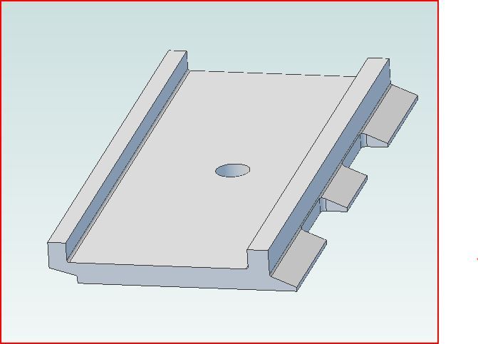
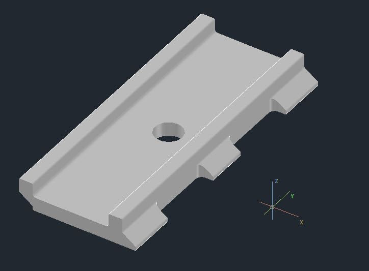
For fun I drew up a rough draft of a 3D AutoCAD solid of your track link. With the right cam software and an end mill with 2mm radius corners (Not standard but not that hard to make from a standard cutter) you should be able to produce it in two settings With most of the cutting on the back side then turn it over to do the base
Of you have a fourth axis driving a rotary table (You would need to make a fixture) you could do it in one setting.
The image below is a solid model. Effectively a void surrounded by a tight skin.
It took me about half an hour.
It was made by drawing a closed polyline of the end section. Polylines are just lines but they are joined end to end. Well not really! but the program treats them as a single entity. The is an option to close them into a loop or leave them open. when making a solid they must be closed.
Next the section was extruded to length with the extrude command. so easy.
Next the hole was made. I simple drew a circle 20mm in diameter, then extruded it to a random length I made it 500mm so it is easy to see it poked through the track and placed it in the centre of the track.
Next the Subtract command was used remove the cylinder from the track piece The cylinder disappeared leaving the hole, Voilà
Finally the cut outs for the hinge on the edge. You guessed it they have to be cut away too.
I drew a rectangle in this case 50mm square, then chamfered two corners to 4mm radius then extruded that to 500mm length. creating a bar with two sides chamfered.
The bar was moved to the correct position cutting through the track and duplicated for the second cut out.
Then the subtract command used again to chop away the recess. Again as with the cylinder the bars disappeared leaving the track.
3D is easy when you think of the work as shown when making the track you only need to memorise a dozen or so commands to start with:
POLYLINE (AND LEARN ABOUT POLYLINE CLOSING, ALL ENDS MUST TOUCH)
SUBTRACT (REMOVES ONE SOLID FROM ANOTHER)
UNION (JOINS TWO SOLIDS TOGETHER)
FILLET (CREATE FILLETS ON SOLIDS AND POLYLINES)
EXTRUDE (EXTRUDE A POLYLINE INTO A 3D SOLID)
CIRCLE (DRAW A CIRCLE)
And set the program to draw autographically unless you want draw an angle,
Before you start watch a couple of getting started videos on you tube to get you familiar with the interface.
The above is for Plain vanilla AutoCAD, other programs should have similar functionality.

Re DXF Files. Unfortunately Autodesk who invented the DXF format change it periodically to keep up with changes to the DWG format. this can create problems if another CAD company does not update their DXF interpreter. A DXF file is simply a plain text file representation of DWG files. This allows other programs to read the text file, CAD CAM programs for instance. When exchanging files with another party find out what version they can read. You can hopefully do a "Save as" to their version.
Regards
John
Edited By John McNamara on 27/10/2013 13:36:45
blowlamp.


