Learning CAD with Alibre Atom3D

Advert

Learning CAD with Alibre Atom3D

Home Forums Model Engineer & Workshop Learning CAD with Alibre Atom3D

Viewing 25 posts - 176 through 200 (of 841 total)
  • Author
    Posts
  • #381597
    JasonB
    Moderator
      @jasonb

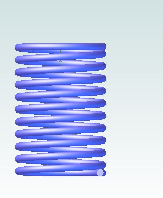
      Have you tried a spring yet?

      spring.jpg

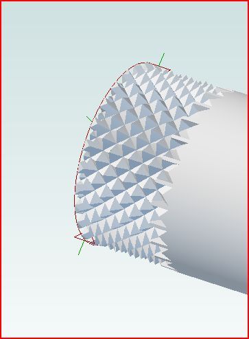
      Or Knurling?

      screw6.jpg

      Edited By JasonB on 20/11/2018 21:00:14

      Advert
      #381633
      Neil Wyatt
      Moderator
        @neilwyatt

        Is the knurling a double cut?

        #381635
        JasonB
        Moderator
          @jasonb

          Yes you will need to do two helical cuts in opposite hands and use circular pattern to get multiple cuts around the rod. Have a look back at my "Sketches" album for a few more pics from when someone was asking about using screwcutting to form a knurl.

          Like screw threads it takes up a lot of memory so will slow things down so not worth using for visual purposes.

          #381648
          John Hinkley
          Participant
            @johnhinkley26699

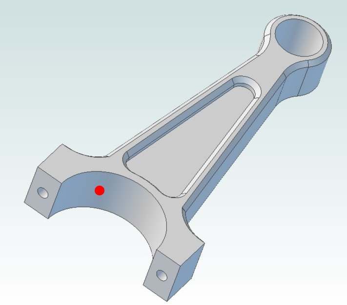
            As previously posted on this thread and others, I'm refining my engine design and come up against another problem. I wish to "drill" an oil hole in the conrod for the escape of pressurised oil from the crankshaft as depicted below and with the position roughly as indicated by the red spot. That is, centrally placed in the longitudinal bearing surface and radially at 45° to the median. I've tried a number of methods, none of which are viable. Any advice, please?

            conrod

            Thanks,

            John

            #381649
            David Jupp
            Participant
              @davidjupp51506

              John,

              You'll need a plane or an existing flat face to place the sketch of the hole outline on. Create a new plane having the required orientation. You may have to tackle this in more than one step – for example create a plane at specified angle to an existing plane – then create another one that is offset from or at another angle to the first (just an example).

              #381660
              JasonB
              Moderator
                @jasonb

                As David says you need an angled Plane. Not quite sure how Atom handles then but when I had the basic Albre PE I often found it easier to draw a simple shape with one edge at the angle I wanted and then extrude it. you can then add the plate using the surface just created as the reference. That extrusion can themn be suppressed so it doe snot show on teh finished part.

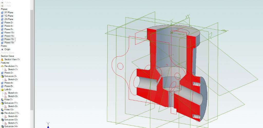
                This is a valve body that has quite a few planes added both for the flanges and also angled ones for the passages.

                planes.jpg

                #381661
                John Hinkley
                Participant
                  @johnhinkley26699

                  Thank you, David. I didn't know that you could introduce new planes! I'll have to look that up and play around with it this afternoon.

                  John

                  #381668
                  John Hinkley
                  Participant
                    @johnhinkley26699

                    ……and thank you, Jason. Plenty to get my head around.

                    John

                    #381671
                    Neil Wyatt
                    Moderator
                      @neilwyatt
                      Posted by John Hinkley on 21/11/2018 12:19:27:

                      Thank you, David. I didn't know that you could introduce new planes! I'll have to look that up and play around with it this afternoon.

                      John

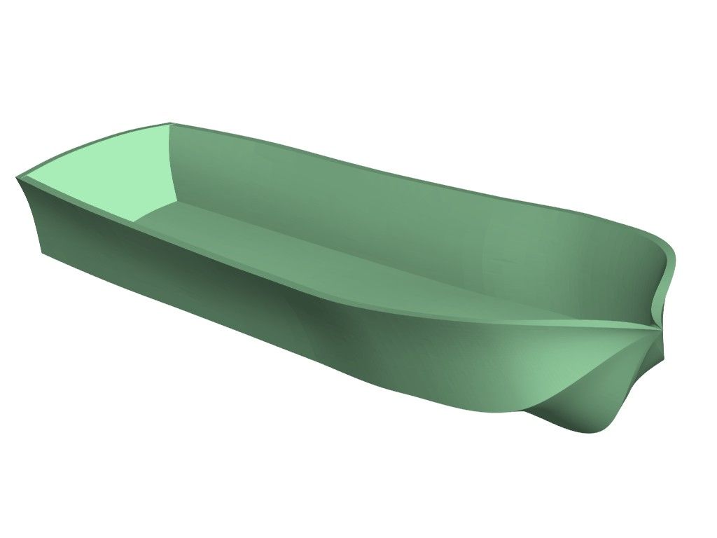
                      The planes are very powerful. I made this 'hull' but creating a plane (parallel to the original X/Y plane) for each section on a plan, drawing the sections on the planes and lofting the shape. I used the same technique for the aircraft I have posted above.

                      asrl.jpg

                      #381690
                      John Hinkley
                      Participant
                        @johnhinkley26699

                        I did it! Just set up a new plane with a right click, select the geometry and angle. Select the newly created plane and drew a circle which was then extrude cut "all through". Whether that will work with more complicated designs remains to be seen, but it's a start.

                        John

                        #381700
                        blowlamp
                        Participant
                          @blowlamp
                          Posted by John Hinkley on 21/11/2018 10:24:33:

                          As previously posted on this thread and others, I'm refining my engine design and come up against another problem. I wish to "drill" an oil hole in the conrod for the escape of pressurised oil from the crankshaft as depicted below and with the position roughly as indicated by the red spot. That is, centrally placed in the longitudinal bearing surface and radially at 45° to the median. I've tried a number of methods, none of which are viable. Any advice, please?

                          conrod

                          Thanks,

                          John

                          Would Atom let you draw a long & thin rectangle at 45 degrees on the mid-plane of the conrod that could be 'Revolved' around either of its long sides to create a solid cylinder which could then be 'Subtracted' from the conrod to leave the oil hole?

                          Martin.

                          #381701
                          Neil Wyatt
                          Moderator
                            @neilwyatt
                            Posted by blowlamp on 21/11/2018 17:38:30:

                            Posted by John Hinkley on 21/11/2018 10:24:33:

                            As previously posted on this thread and others, I'm refining my engine design and come up against another problem. I wish to "drill" an oil hole in the conrod for the escape of pressurised oil from the crankshaft as depicted below and with the position roughly as indicated by the red spot. That is, centrally placed in the longitudinal bearing surface and radially at 45° to the median. I've tried a number of methods, none of which are viable. Any advice, please?

                            conrod

                            Thanks,

                            John

                            Would Atom let you draw a long & thin rectangle at 45 degrees on the mid-plane of the conrod that could be 'Revolved' around either of its long sides to create a solid cylinder which could then be 'Subtracted' from the conrod to leave the oil hole?

                            Martin.

                            Yes you could do it that way, but putting it on a plane has a lot more uses.

                            #381706
                            JasonB
                            Moderator
                              @jasonb

                              You would have to add an axis to revolve the rectangle around so may as well just add the plane.

                              Though you could extrude a sketched rectangle drawn at 45 degrees equally about the mid point and then round the 4 corners to get a round hole but it's a bit long winded.

                              John, its about time you started an assembly of these parts then you can waste time turning the crankshaft around and watching the pistons go up and down. There is something about assemblies coming in in 275.

                              #381709
                              David Jupp
                              Participant
                                @davidjupp51506

                                Just goes to show there is rarely ONE single way to tackle anything – none are 'wrong'.

                                You can revolve about an edge of the rectangle – you don't have to add an axis.

                                Edited By David Jupp on 21/11/2018 18:39:57

                                #381720
                                John Hinkley
                                Participant
                                  @johnhinkley26699

                                  Jason,

                                  I've given some thought to experimenting with assemblies, but have held off until I've "made" more bits. I'm rapidly approaching the point where I can't put it off much longer! I feel a session watching YouTube tutorials coming on.

                                  John

                                  #381723
                                  blowlamp
                                  Participant
                                    @blowlamp

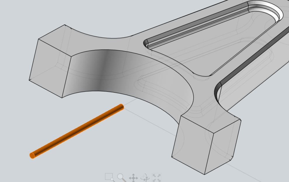
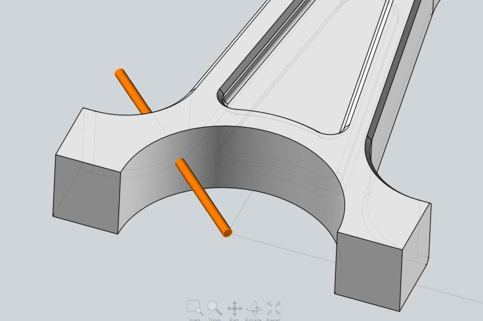
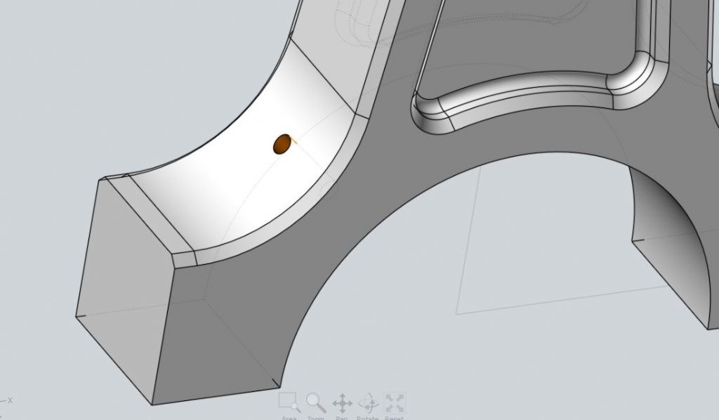
                                    I don't have Atom, so for fun, I had a play in MoI.

                                    The thickness of the conrod is centred about the Origin plane i.e., equally above and below the plane, whilst the big end bearing is centred at the Origin.

                                    I created a long cylinder (orange colour) in the first picture from a solid primitive (rather than a revolved rectangle) with its end centred on the Origin and pointing down along the Y axis.

                                    con1.jpg

                                    In picture two, I've rotated the cylinder about the Origin into the 45 degree position.

                                    con2.jpg

                                    Picture three shows the result after subtracting the cylinder from the conrod.

                                    con3.jpg

                                    Martin.

                                    #381802
                                    KEITH BEAUMONT
                                    Participant
                                      @keithbeaumont45476

                                      I have received an e-mail from Alibre saying that the latest update of Windows 10 contains a bug that makes Alibre Design and Atom 3D unusable and that downloading Alibre 2018,2 corrects this and is required for all that update Windows 10.

                                      My Pc has already updated to the latest version of Win 10, so I have installed the updated Alibre 2018,2.

                                      My Norton Virus software advised against it ,saying it has insufficient knowledge of its safety..

                                      I am suprised that no other mention of this has been noted on this forum and I hope I have not walked into a problem.

                                      The download does not delete the previous version ,so you get another 372 MB of disc space used.

                                      Keith

                                      #381808
                                      David Jupp
                                      Participant
                                        @davidjupp51506

                                        Keith,

                                        The new download won't delete the previous download – why would you expect it to ? If I were you I'd hang on to the old download just in case you have a problem and need to revert (only delete the old installer when you have confirmed success with the new one).

                                        Running the new installer will update Atom3D to v2018.2

                                        Note that if you run into the problem with Win10 1809, the new Atom3D 2018.2 allows you to make a setting to resolve the issue BUT this is not active by default. See this article for full details.

                                        Norton probably hasn't caught up yet – v2018.2 was only released this week. Is your Norton up to date? I'll pass on that Norton flagged an issue.

                                        #381809
                                        JasonB
                                        Moderator
                                          @jasonb

                                          My Norton did not bat an eyelid when I updated yesterday.

                                          #381813
                                          KEITH BEAUMONT
                                          Participant
                                            @keithbeaumont45476

                                            Thanks for the replies. I was begining to think I might have been caught out with a nasty.

                                            Keith

                                            #381830
                                            Neil Wyatt
                                            Moderator
                                              @neilwyatt

                                              My computer hasn't been hit with the 1809 happy stick yet.

                                              I'm worried it will affect my access to remote networking.

                                              I trust Alibre have pointed out yet another bug with this ill-starred update to Microsoft?

                                              Neil

                                              #381836
                                              John Barber 5
                                              Participant
                                                @johnbarber5

                                                Many thanks for the opportunity to try Alibre. I'm enjoying it and generally getting on well, but I do have a couple of questions about working on drawings.

                                                1. After zooming and panning is there a quick way to reset the view to show the whole sheet?

                                                2. When creating a section view, how do you ensure the line defining the section goes precisely through the axis of a hole? When I just tried to dimension a 4.5mm hole in a section view, instead of getting (dia)4.5, I got 4.499, so I can only assume that the section plane position was slightly off

                                                #381847
                                                JasonB
                                                Moderator
                                                  @jasonb

                                                  Welcome John.

                                                  1. Along the very top left of the screen you have a series of isometric cubes with one yellow face, these allow you to jump to a particular view, the furthest of these cubes is all yellow and that will take you back to a home view which can be altered by the arrow at it's side.

                                                  2. It is possibly that your circle snapped to the axis, if you go back and set a dimension of zero from that axis you should get the diameter displayed.

                                                  #381854
                                                  David Jupp
                                                  Participant
                                                    @davidjupp51506

                                                    Another tip for getting back to showing the whole design (zoom extents) – press the Home key on the keyboard..


                                                    That also reminds me – you can program pretty much every button function to a keyboard shortcut of your choice. You can even override the default shortcuts if you prefer.


                                                    When placing a line in 2D drawing to create a section view, watch out for circle centres, and 'ghost lines' that help you with alignment. These should appear more or less 'magically'. If they don't we may have to explore some settings. 

                                                    You can also apply sketch constraints working in a 2D view.

                                                    Edited By David Jupp on 22/11/2018 15:54:34

                                                    #381883
                                                    duncan webster 1
                                                    Participant
                                                      @duncanwebster1

                                                      apologies if this has already been answered, 197 posts is a lot to trawl through.

                                                      I've got it downloaded and running, and can create the first 2 shapes, but the left/right mouse click and drag don't work, and it doesn't appear to be clicking to any form of grid or feature, so the 10 dia boss might well not be truly coaxial to the base. Then when I try to create the 6 dia tapered hole, the outward box isn't checked by default. If I enter 2 and then select outward it changes to -2 and vice versa.

                                                      If I then select the cylindrical feature of the 25 dia base and go through the chamfer routine it chamfers both top and bottom edges, which is not I think what I want.

                                                      I'm obviously being dumb, but can anyone point me in the right direction

                                                    Viewing 25 posts - 176 through 200 (of 841 total)
                                                    • Please log in to reply to this topic. Registering is free and easy using the links on the menu at the top of this page.

                                                    Advert

                                                    Latest Replies

                                                    Viewing 25 topics - 1 through 25 (of 25 total)
                                                    Viewing 25 topics - 1 through 25 (of 25 total)

                                                    View full reply list.

                                                    Advert

                                                    Newsletter Sign-up