Learning CAD with Alibre Atom3D

Advert

Learning CAD with Alibre Atom3D

Home Forums Model Engineer & Workshop Learning CAD with Alibre Atom3D

Viewing 25 posts - 151 through 175 (of 841 total)
  • Author
    Posts
  • #380931
    David Jupp
    Participant
      @davidjupp51506

      Graham,

      Within a sketch you can always delete parts of the sketch if they are wrong (or you can move them, resize them etc.). You must go into 'select mode' (the cursor icon in the ribbon) – otherwise the sketching tool you have been using remains active, once in select mode you can do your delete, drag etc.  You can also exit the sketching tool currently in use by pressing Esc.

      Don't worry about sketch number getting high – you can rename sketches (it is good practice anyway to give a meaningful name).


      Edited By David Jupp on 16/11/2018 16:20:38

      Edited By David Jupp on 16/11/2018 16:22:45

      Advert
      #380948
      Graham Titman
      Participant
        @grahamtitman81812

        Thanks Jason i am using a laptop big mistake the icon is only match head size.David when you get so far 35 times and cannot get any further it's called ********** frustrating not good practice.No offence but the magazine instructions do not always match what's on the small screen.Is it possible to put it on another computer?Thanks Graham

        #380952
        mick
        Participant
          @mick65121

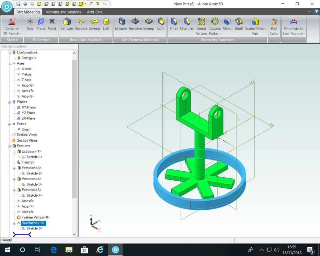
          Right, I'm getting on quite well with the first exercise but I'm trying to generate the six spoke pattern of the wheel, everything is okay except there's no 'axis 6' in the design explorer to establish the centre so I can't complete the operation, I've tried clicking on most options but all that's displayed are the three normal axis selections. Thanks in anticipation.

          #380954
          Neil Wyatt
          Moderator
            @neilwyatt
            Posted by Graham Titman on 16/11/2018 15:50:17:

            Hi how do you do a delete if you make a mistake one wrong mouse click and no matter how far you have got you have to start again.Sketch 45 before you ask and getting very frustrated

            You may be trying to make your sketches too complex.

            It's best to keep the sketches simple, and produce complexity by building up parts from multiple sketches.

            As well as the undo button, if you go wrong you can delete, edit or 'trim' unwanted elements of a sketch.

            I started trying to draw complex shapes exactly how I wanted them, but discovered it's best to roughly arrange what I want by eye then edit and use dimensions to move the elements and get exactly what I want.

            You can move to another computer, I think David explained how to deactivate the licence on one computer and move it to another further up this thread.

            Neil

            #380956
            JasonB
            Moderator
              @jasonb

              Mick, two pages above you should have created "axis 6" page 93 of the pdf.


              Graham, if you are getting stuck at the same point, post a screen shot and tell us what you are wanting to do.

              Edited By JasonB on 16/11/2018 18:29:28

              #380961
              David Jupp
              Participant
                @davidjupp51506

                If icons are really small – one potential cause is a relatively small, but hi-resolution, screen. If you saw High DPI, or 4K in the marketing blurb for your computer you may suffer from this,

                There are some changes you can make to help – see this article

                Transferring to another computer is dealt with here , it's written for Alibre Design, but the process is the same for Atom3D. You can install on multiple computers, but only have the activation live on one at a time. The non-activated computers work in 'Viewer' mode (can't edit or save).

                #381041
                mick
                Participant
                  @mick65121

                  Hi. Jason. That was my mistake, completely missed that operation, but, I've generated the rectangle that will become the wheel, entered all the required information and the circle generates, only problem is its about half an inch away from the spokes. When I've generated the rectangle it remains red, when I select 2D the out line is blue, but I can't get the whole rectangle to become blue, is this a problem. I generate the rectangle at a point away from the spoke as indicated in the pdf. Thanks.

                  #381052
                  JasonB
                  Moderator
                    @jasonb

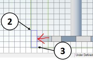
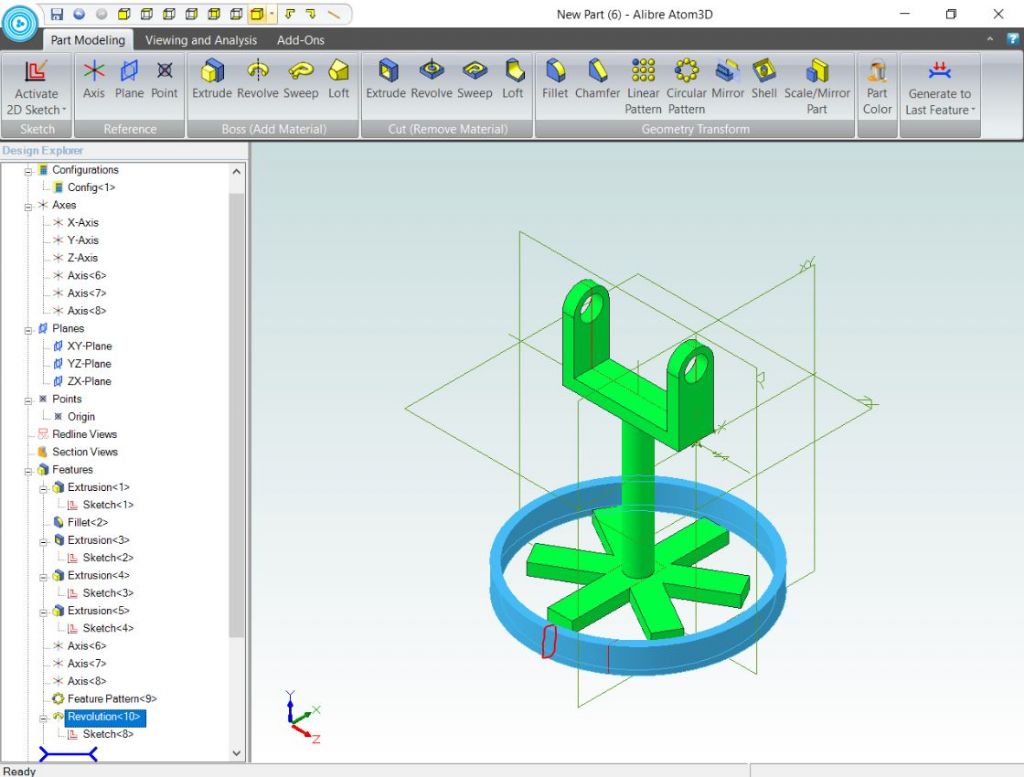
                    Mick, when you draw the rectangle that will become the rim one side of it should be in line with the end of the spoke as I have shown with the red arrow. Once rotated this will give the right diameter rim that will be in contact with teh spoke ends not spaced away from it.

                    rim.jpg

                    #381059
                    David Jupp
                    Participant
                      @davidjupp51506


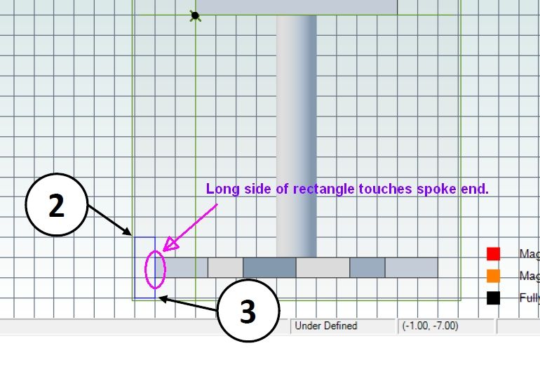
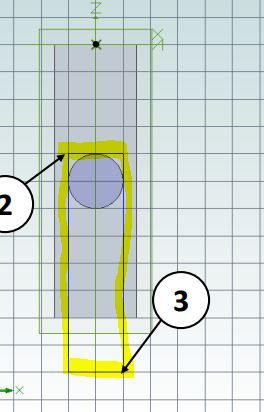
                      The rectangle which is revolved to form the wheel rim is shown in the exercise manual as drawn just touching the end of one of the spokes.

                      atom3d wheel rim.jpg

                      Rectangle corner indicated by circle 3 in the Manual should be at same Z co-ordinate as end of spoke.  Are you definitely sketching on the YZ plane ?

                      The rectangle is only blue whilst being 'dragged' – as soon as you finish placing it (click on second corner) it'll switch to another colour. The image in the manual looks to me as though it has been snapped just before clicking that second corner.

                      Does you wheel rim have a diameter that is too large, or is it 'out of plane' with respect to the spokes?


                      Edited By David Jupp on 17/11/2018 16:25:18

                      #381062
                      David Jupp
                      Participant
                        @davidjupp51506

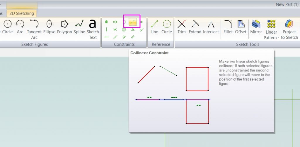
                        You may be able to fix the position of your rectangle by applying a co-linear constraint between the spoke end, and one side of the rectangle.

                        co-linear.jpg

                        #381066
                        Neil Wyatt
                        Moderator
                          @neilwyatt
                          Posted by mick on 17/11/2018 14:39:41:

                          Hi. Jason. That was my mistake, completely missed that operation, but, I've generated the rectangle that will become the wheel, entered all the required information and the circle generates, only problem is its about half an inch away from the spokes. When I've generated the rectangle it remains red, when I select 2D the out line is blue, but I can't get the whole rectangle to become blue, is this a problem. I generate the rectangle at a point away from the spoke as indicated in the pdf. Thanks.

                          Can you share a 3D screenshot?

                          It should be easy to get it all lined up, but we need to know how it's 'out'.

                          Thanks

                          Neil

                          #381092
                          Graham Titman
                          Participant
                            @grahamtitman81812

                            Hi Jason sorry i have only just seen your comment. The problem i was having was trying to get past fig 8 the square was there but not the circle inside after changing from the laptop to the desktop i deleted the icon from the tool bar of windows by mistake and had to start from the desktop and after that it worked perfectly within twenty minutes I had managed to complete the tutorial from the magazine.Very pleased with it two years ago tried fusion and had no success at all with it,Thanks for all your help I shall probably need it when I have another play in a couple of days.

                            #381227
                            Ken Strauss
                            Participant
                              @kenstrauss65445

                              So far so good but has anyone tried Atom3d in conjunction with a CAM package? There doesn't seem to be a .dxf export and .stl is not really appropriate. The Mecsoft CAM costs from than Atom3d!

                              #381229
                              David Jupp
                              Participant
                                @davidjupp51506

                                Atom3D does have DXF export (and DWG) from the 2D drawing workspace.

                                Some CAM packages are designed to work with STL files. STEP should work well for many.

                                AlibreCAM can be used in 'FreeMill' mode without a licence – albeit with limited capability (but enough for some).

                                #381262
                                mick
                                Participant
                                  @mick65121

                                  Another day another problem. I still can't get the rim to contact the spokes and I can't seem to upload a screen shot, so I've sent the screen shot to Neil to post. Started the base, first thing is I don't have a grid option in the ribbon and so can't turn off 'grid and snap' or check DOF color is on. I've generated the base but the rectangle by two corners won't generate a rectangle on the face of the base, also I don't appear to have a rectangle by three corners option available. Thanks.

                                  #381267
                                  JasonB
                                  Moderator
                                    @jasonb

                                    Mick, are you looking at the Alibre design tutorial again as those are not Atom options in the ribon, they are in design. Once again you need to be using this tutorial

                                    Edited By JasonB on 18/11/2018 18:36:52

                                    #381288
                                    Neil Wyatt
                                    Moderator
                                      @neilwyatt

                                      Hello Mick, here's your pic:

                                      3d.jpg

                                      The basic problem is clear enough, you need to move your rectangle so that it's touching the end of a spokes before revolving it.

                                      Neil

                                      #381290
                                      JasonB
                                      Moderator
                                        @jasonb

                                        Not so neil. The whole thing has been drawn off axis. The XY plane should pass through the middle of the shaft but it is off to the front. Will need to look back and see what step mick has missed. Suspect it was early on when the "C" shaped part was sketched.

                                        Sketch should be where I have added it in red

                                        mick rim.jpg


                                        Edited By JasonB on 18/11/2018 20:52:01

                                        Edited By JasonB on 18/11/2018 20:54:39

                                        #381321
                                        JasonB
                                        Moderator
                                          @jasonb

                                          Right Mick, I can see what you have done.

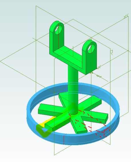
                                          When you drew the first spoke you drew it at right angles to the "C" shaped part. You should have drawn it in line with that. This will mean that when you draw the rectangle that forms the rim on the YZ plane you will be able to place it at the end of the spoke.

                                          This shows you have drawn teh sketch at right angles, it should be where I have dotted it in red

                                          mick rim3.jpg


                                          Easiest way to sort it out will be to RIGHT click sketch 4 down the left hand side and trim your rectangle to remove it then redraw the right way round as highlighted below

                                          mick rim2.jpg

                                          Next RIGHT click Revolution 10 down the left side and select delete, then RIGHT click Sketch 8 and delete that.

                                          Now you can draw the rectangle that forms the rim on the YZ plane and then revolve it.

                                          If you are not sure of that then Read your PMs and send me the part file

                                          Edited By JasonB on 19/11/2018 07:59:46

                                          Edited By JasonB on 19/11/2018 08:09:18

                                          #381325
                                          mick
                                          Participant
                                            @mick65121

                                            Hi. Jason.

                                            First off, thank you for all your input, it can't have escaped your notice that my IT skills are some what limited, but I really want to get to grips with the basics of this software.

                                            The only exercise package that I can locate is the one I'm following and in my own defense there isn't any notice that I've come across that informs me otherwise. I don't have the benefit of duel monitors and so the only way I have of generating the images is to read about ten pages of PDF, take notes, go back to the part and execute, save and exit then repeat the process, this way mistakes are bound to occur. My plan now is to copy the exercise from your link onto my wife's laptop and start from scratch reading the tutorial one page at a time and generating the part with the instructions directly in front of me. I'll let you know how I get on. Thanks again.

                                            #381349
                                            Neil Wyatt
                                            Moderator
                                              @neilwyatt
                                              Posted by mick on 19/11/2018 08:50:50:

                                              The only exercise package that I can locate is the one I'm following and in my own defense there isn't any notice that I've come across that informs me otherwise. I don't have the benefit of duel monitors and so the only way I have of generating the images is to read about ten pages of PDF, take notes, go back to the part and execute, save and exit then repeat the process, this way mistakes are bound to occur.

                                              As you must be using Windows 7 or later, you shoudl be able to switch windows easily enough, no need to save and close.

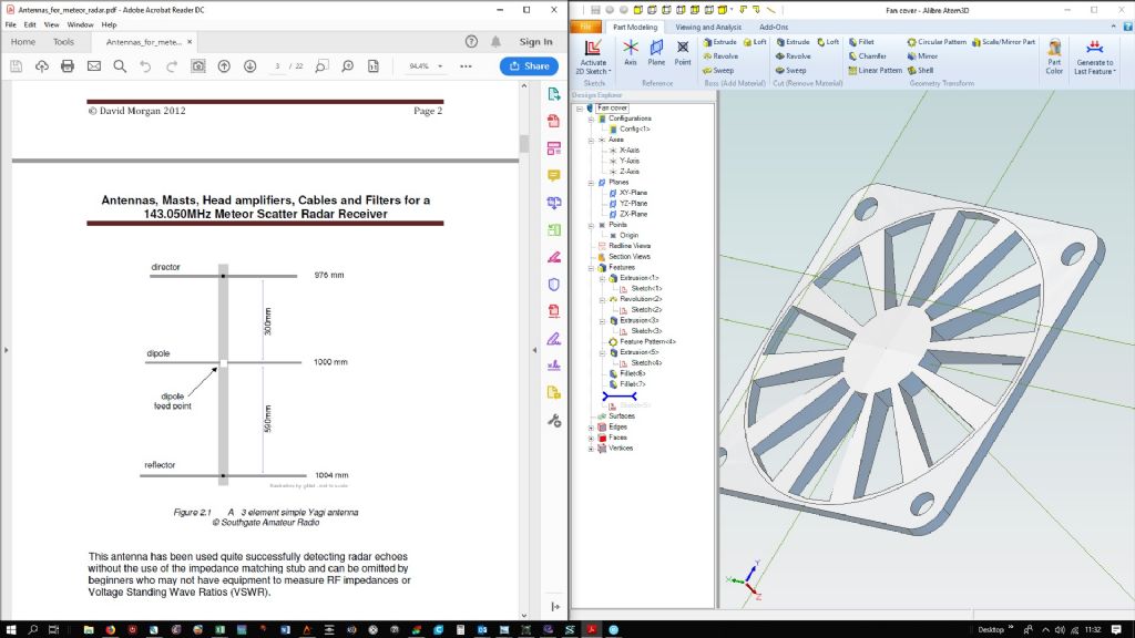
                                              Or drag the top bar of the alibre window to the right side of the display and of acrobat to the left edge.

                                              You will then have the two windows occupying the two sides of the screen like this example:

                                              split screen.jpg

                                              #381375
                                              Ken Strauss
                                              Participant
                                                @kenstrauss65445

                                                If you prefer to have both windows full screen you can press Alt-Tab to swap which is on top.

                                                #381438
                                                blowlamp
                                                Participant
                                                  @blowlamp

                                                  c8b3ca4e7780e77cfaf7f6d64e423ff2.jpg

                                                  #381510
                                                  David Jupp
                                                  Participant
                                                    @davidjupp51506

                                                    For information – v2018.2 of Alibre Atom3D is now available. You may get a message to that effect on launching Atom 3D, or you can download the installer from here

                                                    2018.2 includes a fix for a consequence of a Windows update it also makes helical features available in Atom3D.

                                                    #381596
                                                    Neil Wyatt
                                                    Moderator
                                                      @neilwyatt

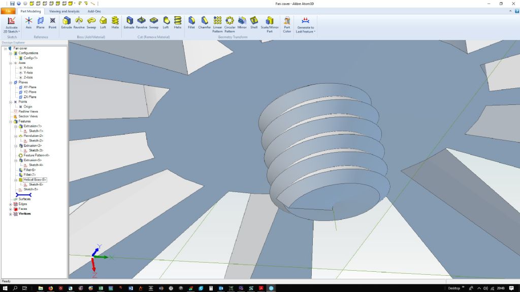
                                                      Quick and dirty test of the 3D Helix tool, rough and ready M6 thread:

                                                      screwed.jpg

                                                    Viewing 25 posts - 151 through 175 (of 841 total)
                                                    • Please log in to reply to this topic. Registering is free and easy using the links on the menu at the top of this page.

                                                    Advert

                                                    Latest Replies

                                                    Viewing 25 topics - 1 through 25 (of 25 total)
                                                    Viewing 25 topics - 1 through 25 (of 25 total)

                                                    View full reply list.

                                                    Advert

                                                    Newsletter Sign-up